Sony VPL-VW1100ES User manual

Operating Instructions
Before operating the unit, please read this manual and supplied Quick
Reference Manual thoroughly and retain them for future reference.
VPL-VW1100ES
4-486-360-12 (1)
Video Projector

2
Table of Contents
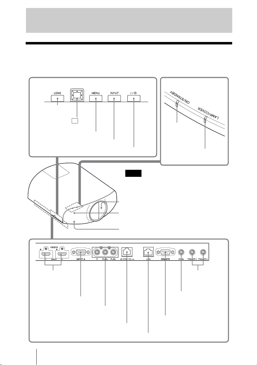
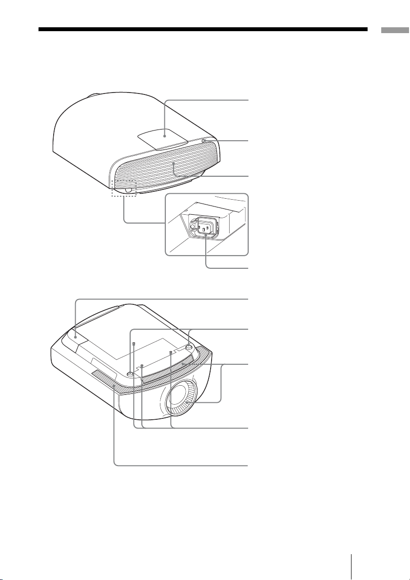
Front/Right Side ................................. 4
Rear/Bottom ....................................... 5
Remote Control .................................. 6
Preparation 1: Installing the Unit ....... 7
Installing the Unit ......................... 7
Preparation 2: Adjusting the Picture
Position .............................................. 8
Preparation 3: Connecting the
Unit .................................................. 13
Connecting to a VCR ................. 13
Connecting to a Computer ......... 15
Connecting to a 3D Sync
Transmitter ................................. 16
Projecting the Picture ....................... 17
Turning Off the Power ............... 18
Watching 3D Video Images ............. 18
Using the 3D Glasses ................. 19
Charging the 3D Glasses ............ 21
Using the Picture Position ................ 22
Selecting the Aspect Ratio According to
the Video Signal ............................... 24
Selecting the Picture Viewing
Mode ................................................ 27
Using “ImageDirector3” to Adjust the
Picture Quality ..................................28
Operation through the Menus ...........29
Picture Menu ....................................31
Screen Menu .....................................37
Setup Menu .......................................40
Function Menu .................................42
Installation Menu ..............................46
Information Menu .............................49
About the Preset Memory No. ....49
Displaying the Control Window of the
Unit with a Web Browser .................51
Operating the Control Window ........52
Switching the Page .....................52
Setting the Access Limitation .....52
Confirming the Information
Regarding the Unit ......................52
Operating the Unit from a
Computer ....................................52
Using the E-mail Report
Function ......................................53
About the Control for HDMI ............55
About DCI specification ...................56
About the x.v.Color ..........................56
Location of Controls
Connections and
Preparations
Projecting
Using the Menus
Using Network Features
Others

3
About the simulated 3D feature .......56
Troubleshooting ...............................57
Warning Indicators .....................60
Message Lists .............................61
Replacing the Lamp and Cleaning the
Ventilation Holes (intake) ................63
Cleaning ...........................................66
Specifications ...................................67
Preset Signals .............................68
Input Signals and Adjustable/
Setting Items ...............................71
Compatible 3D Signals ...............73
3D Signals and Adjustable/Setting
Items ..........................................73
Aspect Mode ...............................74
Storage Conditions of Adjustable/
Setting Items ...............................75
Projection Distance and Lens Shift
Range ...............................................78
Dimensions .......................................82
Index ...............................................85

4
Front/Right Side
You can use the buttons on the control panel with the same names as those on the remote
control to operate the unit.
Location of Controls
INPUT button (1page 17)
MENU button (1page 29)
ON/STANDBY
indicator
(1page 9)
Remote control detection area
?/1(ON/STANDBY) button (1page 9) LAMP/COVER indicator
(1page 60)
M/m/</,(arrow)/ (enter)
button (1page 29)
Y PB/CBPR/CRconnector (phono type)
(1page 14)
INPUT A connector (1page 15)
HDMI 1/2 connector
(1page 13)
REMOTE connector
Connects to a computer,
etc. for remote control.
(1page 28)
TRIGGER 1/
TRIGGER 2
connector (1
page 46)
While the ON/STANDBY indicator lights in orange,
the power saving mode is on. (1page 41)
Note
Control panel
LENS button
(1page 8)
IR IN connector
Inputs signals to control
the unit
Lens protector
3D Sync Transmitter area
3D SYNC connector (1page 16)
LAN connector (1page 51)

5
Location of Controls
Rear/Bottom
Ventilation holes
(exhaust)
Lamp cover (1page 63)
AC IN socket
Projector suspension
support attaching hole
(1page 83)
Front feet (adjustable) (1page 12)
Ventilation holes (intake)
Remote control detector
(1page 8)
Ventilation holes (intake)
AC inlet cover (supplied)
For details on how to attach the AC
inlet cover, see Quick Reference
Manual (separately printed
manual).

6
Remote Control
INPUT button (1page 17)
Infrared transmitter
?/1(ON/STANDBY)
button (1page 9)
COLOR SPACE button
(1page 36)
M/m/</,(arrow)/ (enter)
buttons (1page 29)
RESET button (1page 30)
CONTRAST +/– button
(1page 33)
BRIGHTNESS +/– button
(1page 33)
LIGHT button
Illuminates the buttons on
the remote control.
CALIBRATED PRESET
buttons (1page 27)
3D button (1page 19)
ASPECT button
(1page 24)
POSITION button
(1page 22)
SHARPNESS +/– button
(1page 34)
MENU button (1page 29)
ADVANCED IRIS button
(1page 32)
COLOR TEMP button
(1page 34)
REALITY CREATION button
(1page 32)
BLACK LEVEL button
(1page 35)
GAMMA CORRECTION
button (1page 35)
MOTION ENHANCER
button (1page 33)
LENS ADJUSTMENT buttons
(1page 9)

7
Connections and Preparations
This section describes how to install the unit and screen, how to connect the equipment
from which you want to project the picture, etc.
Preparation 1: Installing the Unit
The lens shift allows you to have broader options for placing the unit and viewing pictures
easily.
The installation distance between the unit and a screen varies depending on the size of the
screen or whether or not you use the lens shift features. Install this unit so that it fits the
size of your screen. For details on the distance between the unit and the screen (the
projection distance) and the size of projected video, see “Projection Distance and Lens
Shift Range” (1page 78).
1Position the unit parallel to the screen.
2Project an image on the screen and adjust the picture so that it fits the
screen (1page 8).
When using a screen with an uneven surface, stripes pattern may rarely appear on the screen
depending on the distance between the screen and the unit or the zooming magnifications. This is
not a malfunction of the unit.
When installing the unit on the ceiling
To dealers
Use the Sony PSS-H10 Projector Suspension Support, and take measures to prevent
falling using wire, etc.
For details, refer to the installation manual for dealers of the PSS-H10.
Connections and Preparations
Installing the Unit
Note
Screen
Top view

8
Preparation 2: Adjusting the Picture Position
Project an image on the screen and then adjust the picture position.
Tips
•The
?/1(ON/STANDBY), INPUT, MENU, and M/m/</,/ (joystick) buttons on the side
panel of the unit function the same as those on the remote control. The LENS button functions in
the same way as the LENS ADJUSTMENT (FOCUS, ZOOM, SHIFT) buttons of the remote
control.
• When adjusting the lens, each time you press the LENS button on the unit, the lens adjustment
function switches between “Lens Focus,” “Lens Zoom” and “Lens Shift.”
Depending on the installation location of the unit, you may not control it with the remote control. In
this case, point the remote control at the remote control detector of the unit or the screen.
Note
ON/STANDBY indicator
Remote control detector
3, 4, 5
LENS
ADJUSTMENT
buttons
2
1
?/1(ON/
STANDBY)
button

9
Connections and Preparations
1After connecting the AC power
cord to the unit, plug the AC
power cord into a wall outlet.
The ON/STANDBY indicator lights in
red and the unit goes into standby mode.
2Press the ?/1(ON/STANDBY)
button to turn on the unit.
The lens protector will open.
The ON/STANDBY indicator flashes in
green, and then lights in green.
3Adjust the focus.
Press the LENS ADJUSTMENT
(FOCUS) button to display the Lens
Focus adjustment window (test pattern).
Then adjust the focus of the picture by
pressing the M/m/</,buttons.
Tip
When “Lens Control” is set to “Off” on the
Installation menu, you cannot adjust the
focus, the picture size or the proper position by
pressing the FOCUS, ZOOM or SHIFT buttons
(1page 46).
When “Test Pattern” is set to “Off” on the
Function menu, the test pattern is not
displayed (1page 45).
Adjust the lens by using buttons on the remote
control or the control panel of the unit. Never
make adjustments by directly turning the lens
with your hands, which may cause damage or
malfunction to the unit.
4Adjust the picture size.
Press the LENS ADJUSTMENT
(ZOOM) button to display the Lens
Zoom adjustment window (test pattern).
Then adjust the size of the picture by
pressing the M/m/</,buttons.
To make the picture larger, press M/,.
To make the picture smaller, press m/
<.
Lights in red.
Flashes in green for
tens of seconds and
then lights in green.
Note

10
5Adjust the picture position.
Press the LENS ADJUSTMENT
(SHIFT) button to display the Lens Shift
adjustment window (test pattern). Then
adjust to the proper position of the
picture by pressing the M/m/</,
buttons.
Tip
The test pattern disappears when no operation
has been performed for one minute.
Whenever you press the button, the test
pattern disappears.
When adjusting the window position, do not
touch the lens unit, otherwise your fingers may
be pinched by the moving parts.
Note

11
Connections and Preparations
To adjust the horizontal position
Press </,.
The picture projected on the screen moves right or left by a maximum of 31% of the screen
width from the center of the lens.
To adjust the vertical position
Press M/m.
The picture projected on the screen moves up or down by a maximum of 80% of the screen
height from the center of the lens.
Top view
: Picture position when moving the picture to the left
at maximum
: Picture position when moving the picture to the
right at maximum
31% 1 screen width 31%
80%
1 screen
height
80%
Side view
: Picture position when moving the picture upward at
maximum
: Picture position when moving the picture downward at
maximum

12
The range to move the picture projected on the screen can be adjusted only within the octagon area
illustrated below. For details, see “Projection Distance and Lens Shift Range” (1page 78).
To adjust the tilt of the installation surface
If the unit is installed on an uneven surface, use the front feet (adjustable) to keep the unit
level.
• If the unit is tilted up or down, the projected image may be trapezoidal.
• Be careful not to catch your finger when turning the front feet (adjustable).
Lens adjustment window (test pattern)
Note
Notes
Range of movement of
the projected picture
Projected Picture
H: Width of the projected picture
V: Height of the projected picture
0.8V
0.8V
0.31H 0.31H
Front feet (adjustable)
Turn to adjust.
The dashed lines show the screen sizes of
each aspect ratio.
1.33:1 (4:3)
2.35:1
1.85:1
1.78:1 (16:9)

13
Connections and Preparations
Preparation 3: Connecting the Unit
When making connections, be sure to do the following:
• Turn off all equipment before making any connections.
• Use the proper cables for each connection.
• Insert the cable plugs properly; poor connection at the plugs may cause a malfunction or
poor picture quality. When pulling out a cable, be sure to pull it out from the plug, not
the cable itself.
• Refer to the operating instructions of the connected equipment.
To connect to equipment with HDMI output connectors
You can enjoy better picture quality by connecting a DVD player/recorder, Blu-ray Disc
player/recorder, or PlayStation®equipped with HDMI output to the HDMI input of the
unit. Moreover, if you have a Control for HDMI compatible equipment, you can operate
the unit synchronizing with the Control for HDMI compatible equipment. For details, see
“HDMI Setting” of the Function menu (1page 43) and “About the Control for
HDMI” (1page 55).
Connecting to a VCR
HDMI cable (not supplied)
: Video signal flow
Right side of the unit
Equipment with HDMI output
connectors
to HDMI output
AV amplifier Speakers
When using an optional HDMI cable, be sure to use a Sony
HDMI cable or other cable that has the HDMI logo.

14
• Use a high-speed HDMI cable. With a standard HDMI cable, images of 1080p, DeepColor, 3D
video and 4K video may not be displayed properly.
• When connecting an HDMI cable to the unit, make sure the Vmark on the upper part of the HDMI
input of the unit and the vmark on the connector of the cable is set at the same position.
• If the picture from equipment connected to the unit with an HDMI cable is not correct, check the
settings of the connected equipment.
To connect to equipment with component video output
connectors
Notes
Component video cable (not supplied)
: Video signal flow
Equipment with component
video output connectors
Right side of the unit
AV amplifier Speakers

15
Connections and Preparations
• Use a high-speed HDMI cable. With a standard HDMI cable, images of 1080p video may not be
displayed properly.
• When connecting an HDMI cable, make sure the Vmark on the upper part of the HDMI input of
the unit and the vmark on the connector of the cable is set at the same position.
• If you set your computer, such as a notebook type, to output the signal to both computer’s display
and this equipment, the picture of the equipment may not appear properly. Set your computer to
output the signal to only the external monitor.
For details, refer to the computer’s operating instructions supplied with your computer. For
settings of the computer, consult with the manufacturer of the computer.
• If the picture from equipment connected to the unit with an HDMI cable is not correct, check the
settings of the connected equipment.
Connecting to a Computer
Notes
HD-Dsub15 pin cable (not supplied) or HDMI cable (not supplied)
: Video signal flow
Right side of the unit
to monitor output
Computer
When using an optional HDMI cable, be sure to use a Sony
HDMI cable or other cable that has the HDMI logo.

16
This unit incorporates a 3D Sync Transmitter. Depending on the installation environment
of the unit, the 3D glasses may not receive 3D signals properly from the unit’s built-in 3D
Sync Transmitter. In this case, connect an optional 3D Sync Transmitter and place it near
your viewing position.
Tip
Place the optional 3D Sync Transmitter directly facing the 3D glasses. Also, in order to stabilize
operation of the 3D glasses, it is recommended that you place the 3D Sync Transmitter near your
viewing position.
CAUTION
Be sure to use straight-type LAN cable of up to 15 m labeled TYPE CM, and do not use
an extension cord.
• The 3D SYNC connector is dedicated for the optional 3D Sync Transmitter. Do not connect
computers or other network devices, to avoid malfunction.
• You can use a 3D Sync Transmitter separate from this unit, using an optional LAN cable (straight-
type).
If the usage environment has interference of a continuous specific frequency, synchronization of
3D image signals and the 3D glasses may be lost. In this case, use a LAN cable labeled Category 7.
When watching 3D images in an environment that has even more interference, use the internal
transmitter.
• Be sure to use cable of up to 15 m, and do not use an extension cord. Also, keep the LAN cable
away from any AC power cords as much as possible.
• Only one 3D Sync Transmitter should be connected to the unit. Connecting multiple 3D Sync
Transmitters may cause a malfunction.
• When connected to the 3D Sync Transmitter, the built-in 3D Sync Transmitter feature of the unit
will turn off. You cannot use both at the same time.
Connecting to a 3D Sync Transmitter
Notes
Right side of the unit
3D Sync Transmitter (not supplied)
LAN cable (not supplied)
: 3D sync signal flow

17
Projecting
This section describes how to operate the unit to view the picture from the equipment
connected to the unit. It also describes how to adjust the quality of the picture to suit your
taste.
Projecting the
Picture
1Power on both the unit and the
equipment connected to the
unit.
2Press INPUT to display the input
palette on the screen.
3Select the equipment from
which you want to display
images.
Press INPUT repeatedly or press M/m/
(enter) to select the equipment from
which to project.
Tips
• When “Auto Input Search” is set to “On” on
the Function menu, only input terminals
with effective signals are displayed in the
input palette.
• When “Status” is set to “Off” on the Setup
menu, the input palette does not appear.
Press the INPUT button to switch between
input terminals in sequence.
• When the “Control for HDMI” is set to “On”
on the Function menu, the input terminal
with effective signals is automatically
displayed, synchronizing with the operation
of the equipment connected to HDMI 1 or
HDMI 2 input of the unit. (Only when the
connected equipment supports Control for
HDMI compatible.)
Projecting
Example: To view the picture from
the video equipment
connected to the HDMI 1
connector of this unit.
To view the picture from Press INPUT
to display
RGB equipment connected
to the INPUT A connector
Input-A
Component equipment
connected to the Y PB/CB
PR/CRconnector
Component
Equipment connected to the
HDMI 1 connector
HDMI 1
Equipment connected to the
HDMI 2 connector
HDMI 2

18
1Press the ?/1(ON/STANDBY)
button.
A message “POWER OFF?” appears on
the screen.
2Press the ?/1(ON/STANDBY)
button again before the
message disappears.
The lens protector will close. Be careful
not to catch your fingers or any objects.
The ON/STANDBY indicator flashes in
green and the fan continues to run to
reduce the internal heat. First, the ON/
STANDBY indicator flashes quickly,
during which you will not be able to
light up the ON/STANDBY indicator
with the ?/1(ON/STANDBY) button.
The fan stops and the ON/STANDBY
indicator changes from flashing green to
remaining red.
The power is turned off completely, and
you can disconnect the AC power cord.
Never disconnect the AC power cord while
the indicator is flashing.
You can turn off the unit by holding the ?/1
(ON/STANDBY) button for about 1 second,
instead of performing the above steps.
Watching 3D Video
Images
You can enjoy powerful 3D video images,
such as from 3D games and 3D Blu-ray
Discs, using the supplied 3D glasses.
1Turn on the HDMI equipment for
3D compatibility connected to
the unit, then play the 3D
content.
For details on how to play 3D content,
refer to the operating instructions for the
connected equipment.
2Turn on the unit and project the
3D video image onto the screen.
For details on how to project the image,
see “Projecting the Picture” (1page
17).
3Turn on the 3D glasses, and
then put them on so that they fit
comfortably.
For details on how to use the 3D glasses,
see “Using the 3D Glasses” (1page
19).
Tips
• The factory default setting for ”2D-3D
Display Sel.” is “Auto” to allow projecting
3D video images automatically when the unit
detects 3D signals.
• To convert 3D video images to 2D video
images, set “2D-3D Display Sel.” to “2D”
(1page 42).
• It may not be possible to display 3D video
image, depending on the type of signal. Set
the “2D-3D Display Sel.” to “3D,” and “3D
Format” to “Side-by-Side” or “Over-Under”
to suit the format of the 3D content you want
to watch (1page 42).
• Use the 3D glasses within the
communication range (1page 20).
Turning Off the Power
Note
Notes

19
Projecting
• You can watch 3D video images only when
signals from HDMI input. When connecting
3D equipment such as a 3D game or 3D Blu-
ray Disc player to the unit, use an HDMI
cable.
• There are differences in perception of 3D
video images among individuals.
• When the temperature of the usage
environment is low, the 3D effect may be
diminished.
Adjusting/Setting the 3D
functions
You can adjust/set the 3D functions by
pressing the 3D button on the remote control
or with the “3D Settings” of the Function
menu. For details, see “3D Settings” (1
page 42).
The 3D glasses receive signals from the 3D
Sync Transmitter built into the front of the
unit, which are reflected to the glasses from
the screen. When watching 3D video images
using the 3D glasses, face squarely toward
the screen.
1Press the power button on the
3D glasses.
The LED indicator lights up in green.
2Put on the 3D glasses.
3Turn toward the screen.
Precautions for use
The 3D glasses receive infrared signals sent
by the 3D Sync Transmitter built into the
front of the unit, which are reflected to the
glasses from the screen.
Misoperation may occur if:
– The 3D glasses do not face the screen
– There are objects blocking the path
between the 3D glasses and the screen
– The viewing position is too far from the
screen or the distance between the unit and
screen is too great
– There are other infrared communication
devices nearby
Using the 3D Glasses
LED indicatorPower button
IR sensor

20
3D glasses communication range
Figures A and B below indicate the communication range of the 3D glasses. If you try to
watch 3D video images from a distance greater than the communication range or install
the unit outside the communication range, the 3D glasses may not be able to display the
images properly. Also, the viable angles and distance vary depending on the screen type,
environment of the room, and installation environment of the unit.
Figure A: 3D sync signal communication distance (Shift Range: 0.5 V)
Figure B: 3D glasses communication range (The figure shows the distance
between the screen and the projector as 8 m.)
Screen
a
Projector
Side view
3D glasses
b
a + b = 13 m (Maximum)
Screen
3D glasses
Top or side view
Approx. 5 m (Maximum)
Other manuals for VPL-VW1100ES
2
Table of contents
Other Sony Projector manuals

Sony
Sony VPL-SW235 User manual

Sony
Sony HDMI VPL-EX7 Service manual

Sony
Sony VPL-MX20 User manual

Sony
Sony VPL-CX86 Reference guide

Sony
Sony VPL-FH31 User manual

Sony
Sony VPH-G70Q User manual

Sony
Sony VPL-V800Q User manual

Sony
Sony VPLGH10 User manual

Sony
Sony VPL-VW85 - Bravia Sxrd 1080p Home Cinema... User manual

Sony
Sony VPL-VW695ES Service manual
Popular Projector manuals by other brands

3M
3M Multimedia Projector MP8746 Operator's guide

Christie
Christie Roadster S+14K-J user manual

NEC
NEC LT157 - XGA LCD Projector Specifications

Digital Projection
Digital Projection HIGHlite 660 Series installation guide

NEC
NEC GT950 - MultiSync XGA LCD Projector Specifications

Sanyo
Sanyo PLC-XU75 Specification sheet