Sony HCD-F200 User manual

SERVICE MANUAL
Sony Corporation
Audio&Video Business Group
Published by Sony Techno Create Corporation
HCD-F200/F500
SPECIFICATIONS
DVD RECEIVER
9-889-150-02
2008H05-1
© 2008.08
Canadian Model
E Model
Australian Model
Russian Model
HCD-F500
AEP Model
UK Model
HCD-F200
Singapore Model
Thai Model
HCD-F200/F500
Ver. 1.1 2008.08
• HCD-F200 is the DVD system, USB, tuner and video section
in DAV-F200.
• HCD-F500 is the DVD system, USB, tuner and video section
in DAV-F500.
Note:
• In this set, repair in the state of having connected with SA-
WSF200.
• In this set, repair in the state of having connected with SA-
WSF500.
Model Name Using Similar Mechanism NEW
DVD Mechanism Type CDM86-DVBU101
Optical Pick-up Block Name KHM-313CAB
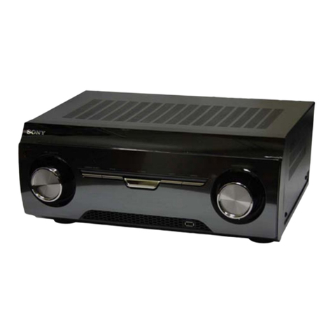
Photo: HCD-F500
This product incorporates copyright protection technology that is
protected by U.S. patents and other intellectual property rights.
Use of this copyright protection technology must be authorized by
Macrovision, and is intended for home and other limited viewing
uses only unless otherwise authorized by Macrovision. Reverse
engineering or disassembly is prohibited.
This system incorporates with Dolby* Digital and Dolby Pro Log-
ic (II) adaptive matrix surround decoder and the DTS** Digital
Surround System.
* Manufactured under license from Dolby Laboratories.
Dolby, Pro Logic, and the double-D symbol are trademarks of
Dolby Laboratories.
** Manufactured under license under U.S. Patent #’s: 5,451,942;
5,956,674; 5,974,380; 5,978,762; 6,487,535 & other U.S. and
worldwide patents issued & pending. DTS and DTS Digital
Surround are registered trademarks and the DTS logos and
Symbol are trademarks of DTS, Inc. © 1996-2007 DTS, Inc.
All Rights Reserved.
This system incorporates High-Definition Multimedia Interface
(HDMITM) technology.
HDMI, the HDMI logo and High-Definition Multimedia Interface
are trademarks or registered trademarks of HDMI Licensing LLC.
“BRAVIA” is a trademark of Sony Corporation.
“S-AIR” and its logo are trademarks of Sony Corporation.
Tuner Section
System PLL quartz-locked digital
synthesizer
FM tuner section
Tuning range
Canadian models: 87.5 MHz - 108.0 MHz
(100 kHz step)
Other models: 87.5 MHz - 108.0 MHz
(50 kHz step)
Antenna (aerial) FM wire antenna (aerial)
Antenna (aerial) terminals
75 ohms, unbalanced
Intermediate frequency 10.7 MHz
Video Section
Outputs VIDEO: 1 Vp-p 75 ohms
COMPONENT:
Y: 1 Vp-p 75 ohms
P
B/CB, PR/CR: 0.7 Vp-p
75 ohms
HDMI OUT: Type A
(19 pin)
Inputs (Analog)
TV (AUDIO IN) Sensitivity: 450/250 mV
Inputs (Digital) SAT/CABLE (COAXIAL)
Impedance: 75 ohms
Output (Digital) (HCD-F200)
Impedance: 75 ohms
DVD System
Laser Semiconductor laser
(DVD: λ= 650 nm)
(CD: λ= 790 nm)
Emission duration: continuous
Signal format system
Canadian and Latin American models:
NTSC
Other models: NTSC/PAL
USB Section
Supported bit rate
MP3 (MPEG 1 Audio Layer-3):
32 kbps - 320 kbps
WMA: 48 kbps - 192 kbps
AAC: 48 kbps - 320 kbps
Sampling frequencies
MP3 (MPEG 1 Audio Layer-3):
32/44.1/48 kHz
WMA: 44.1 kHz
AAC: 44.1 kHz
(USB) port:
Maximum current: 500 mA
– Continued on next page –

HCD-F200/F500
2
NOTES ON CHIP COMPONENT REPLACEMENT
• Never reuse a disconnected chip component.
• Notice that the minus side of a tantalum capacitor may be dam-
aged by heat.
FLEXIBLE CIRCUIT BOARD REPAIRING
• Keep the temperature of soldering iron around 270 °C during
repairing.
• Do not touch the soldering iron on the same conductor of the
circuit board (within 3 times).
• Be careful not to apply force on the conductor when soldering
or unsoldering.
SAFETY-RELATED COMPONET WARNING!
COMPONENTS IDENTIFIED BY MARK 0OR DOTTED LINE
WITH MARK 0ON THE SCHEMATIC DIAGRAMS AND IN
THE PARTS LIST ARE CRITICAL TO SAFE OPERATION.
REPLACE THESE COMPONENTS WITH SONY PARTS
WHOSE PART NUMBERS APPEAR AS SHOWN IN THIS
MANUAL OR IN SUPPLEMENTS PUBLISHED BY SONY.
ATTENTION AU COMPOSANT AYANT RAPPORT
À LA SÉCURITÉ!
LES COMPOSANTS IDENTIFIÉS PAR UNE MARQUE 0SUR
LES DIAGRAMMES SCHÉMATIQUES ET LA LISTE DES
PIÈCES SONT CRITIQUES POUR LA SÉCURITÉ DE FONC-
TIONNEMENT. NE REMPLACER CES COMPOSANTS QUE
PAR DES PIÈCES SONY DONT LES NUMÉROS SONT DON-
NÉS DANS CE MANUEL OU DANS LES SUPPLÉMENTS
PUBLIÉS PAR SONY.
Control unit (HCD-F200)
Output voltage (DIGITAL MEDIA PORT)
DC 5 V
Output current (DIGITAL MEDIA PORT)
700 mA
Dimensions (approx.) 434 mm × 185 mm × 78 mm
(w/h/d)
434 mm × 214 mm × 124 mm
(w/h/d) with stand
Mass (approx.) 3.6 kg
3.7 kg with stand
Control unit (HCD-F500)
Output voltage (DIGITAL MEDIA PORT)
DC 5 V
Output current (DIGITAL MEDIA PORT)
700 mA
Dimensions (approx.) 434 mm × 185 mm × 78 mm
(w/h/d)
434 mm × 214 mm × 124 mm
(w/h/d) with stand
Mass (approx.) 3.6 kg
3.7 kg with stand
Design and specifications are subject to change without
notice.
CAUTION
Use of controls or adjustments or performance of procedures
other than those specified herein may result in hazardous radia-
tion exposure.
Self-diagnosis Function
(
When letters/numbers appear in the
display)
When the self-diagnosis function is activated to
prevent the system from malfunctioning, a 5-
character service number (e.g., C 13 50) with a
combination of a letter and 4 digits appears on
the TV screen or front panel display. In this case,
check the following table.
When displaying the version number
on the TV screen
When you turn on the system, the version
number [VER.X.XX] (X is a number) may
appear on the TV screen. Although this is not a
malfunction and for Sony service use only,
normal system operation will not be possible.
Turn off the system, and then turn on the system
again to operate.
First 3
characters of
the service
number
Cause and/or corrective action
C 13 • The disc is dirty.
Clean the disc with a soft cloth.
• The disc is a format that the
system cannot play.
C 31 The disc is not inserted correctly.
Restart the system, then re-insert
the disc correctly.
E XX
(XX is a
number)
To prevent a malfunction, the
system has performed the self-
diagnosis function.
Contact your nearest Sony
dealer or local authorized Sony
service facility and give the 5-
character service number.
Example: E 61 10
C:13:50
VER.X.XX
This appliance is
classified as a CLASS 1
LASER product. This
marking is located on
the bottom exterior.

HCD-F200/F500
3
1. SERVICING NOTES ............................................. 4
2. GENERAL .................................................................. 8
3. DISASSEMBLY
3-1. Disassembly Flow........................................................... 10
3-2. Panel (Stand Top)............................................................ 11
3-3. Cover (Read-HCD), Holder (Terminal-HCD) ................ 11
3-4. Process In The Solder Bridge ......................................... 12
3-5. Optical Pick-up Block..................................................... 13
3-6. KEY-R/FL/KEY-L/USB Board....................................... 13
3-7. Main Block ..................................................................... 14
3-8. Shield Plate (Front)......................................................... 15
3-9. MAIN Board Block ........................................................ 15
3-10. MAIN Board ................................................................... 16
3-11. DMB-FIT Board ............................................................. 16
3-12. DVD Mechanism Block.................................................. 17
3-13. Motor (Pulley) Assy (Loading) (M001).......................... 17
3-14. Holder (BU) Assy ........................................................... 18
3-15. Lever (BU Lock)............................................................. 18
3-16. Close Lever ..................................................................... 19
3-17. Lever (DIR), Gear (IDL-B) ............................................ 19
3-18. Chassis (Top) .................................................................. 20
3-19. Lever (Loading-L/R)....................................................... 21
3-20. Lever (Disc Sensor)/(Disc Stop)..................................... 22
3-21. Gear (IDL-C) .................................................................. 22
4. TEST MODE ............................................................ 23
5. ELECTRICAL ADJUSTMENT ........................... 28
6. DIAGRAMS
6-1. Block Diagram - DVD SERVO Section -....................... 29
6-2. Block Diagram - MAIN Section -................................... 30
6-3. Block Diagram - HDMI, VIDEO Section - .................... 31
6-4. Block Diagram
- PANEL, POWER SUPPLY Section - ........................... 32
6-5. Printed Wiring Boards - DMB-FIT Section (1/2) -......... 34
6-6. Printed Wiring Boards - DMB-FIT Section (2/2) -......... 35
6-7. Schematic Diagram - DMB-FIT Section (1/4) -............. 36
6-8. Schematic Diagram - DMB-FIT Section (2/4) -............. 37
6-9. Schematic Diagram - DMB-FIT Section (3/4) -............. 38
6-10. Schematic Diagram - DMB-FIT Section (4/4) - ............. 39
6-11. Printed Wiring Board
- MAIN Board (Component Side) -................................ 40
6-12. Printed Wiring Board
- MAIN Board (Conductor Side) -.................................. 41
6-13. Schematic Diagram - MAIN Board (1/3) -..................... 42
6-14. Schematic Diagram - MAIN Board (2/3) -..................... 43
6-15. Schematic Diagram - MAIN Board (3/3) -..................... 44
6-16. Printed Wiring Board - CENTER Board -...................... 45
6-17. Schematic Diagram - CENTER Board -......................... 45
6-18. Printed Wiring Board - FL Board - ................................. 46
6-19. Schematic Diagram - FL Board -.................................... 47
6-20. Printed Wiring Boards - KEY Section -.......................... 48
6-21. Schematic Diagram - KEY Section - .............................. 49
TABLE OF CONTENTS
7. EXPLODED VIEWS
7-1. Rear Cover Section ......................................................... 58
7-2. Front Panel Section......................................................... 59
7-3. Main Section ................................................................... 60
7-4. Chassis Section ............................................................... 61
7-5. DVD Mechanism Deck Section-1
(CDM86-DVBU101) ...................................................... 62
7-6. DVD Mechanism Deck Section-2
(CDM86-DVBU101) ...................................................... 63
7-7. DVD Mechanism Deck Section-3
(CDM86-DVBU101) ...................................................... 64
7-8. DVD Mechanism Deck Section-4
(CDM86-DVBU101) ...................................................... 65
8. ELECTRICAL PARTS LIST .............................. 66

HCD-F200/F500
4
SECTION 1
SERVICING NOTES
Model Part No.
F200: AEP and UK models 3-294-269-0[]
F200: Singapore model 3-294-270-0[]
F500: Canadian model 3-294-272-0[]
F500: Russian model 3-294-274-0[]
F500: Singapore model 3-294-275-0[]
F500: 240V AC area in E model 3-294-276-0[]
F500: Korean and Thai models 3-294-277-0[]
F500: Australian model 3-294-279-0[]
F500: Latin American model
(110 – 240V AC area) 3-294-281-0[]
F500: Mexican model 3-294-282-0[]
F500: Taiwan model 3-294-283-0[]
F200: Thai model 3-452-613-0[]
F500: Iranian model 3-876-712-0[]
F500: Saudi Arabia model 4-114-165-0[]
UNLEADED SOLDER
Boards requiring use of unleaded solder are printed with the lead-
free mark (LF) indicating the solder contains no lead.
(Caution: Some printed circuit boards may not come printed with
the lead free mark due to their particular size)
: LEAD FREE MARK
Unleaded solder has the following characteristics.
• Unleaded solder melts at a temperature about 40 °C higher
than ordinary solder.
Ordinary soldering irons can be used but the iron tip has to be
applied to the solder joint for a slightly longer time.
Soldering irons using a temperature regulator should be set to
about 350 °C.
Caution: The printed pattern (copper foil) may peel away if
the heated tip is applied for too long, so be careful!
• Strong viscosity
Unleaded solder is more viscous (sticky, less prone to flow)
than ordinary solder so use caution not to let solder bridges
occur such as on IC pins, etc.
• Usable with ordinary solder
It is best to use only unleaded solder but unleaded solder may
also be added to ordinary solder.
NOTES ON HANDLING THE OPTICAL PICK-UP
BLOCK OR BASE UNIT
The laser diode in the optical pick-up block may suffer electrostat-
ic break-down because of the potential difference generated by the
charged electrostatic load, etc. on clothing and the human body.
During repair, pay attention to electrostatic break-down and also
use the procedure in the printed matter which is included in the
repair parts.
The flexible board is easily damaged and should be handled with
care.
NOTES ON LASER DIODE EMISSION CHECK
The laser beam on this model is concentrated so as to be focused
on the disc reflective surface by the objective lens in the optical
pickup block. Therefore, when checking the laser diode emission,
observe from more than 30 cm away from the objective lens.
RELEASING THE DISC SLOT LOCK
The disc slot lock function for the antitheft of an demonstration
disc in the store is equipped.
Releasing Procedure:
1. Press the [?/1] button to turn on the system.
2. Press the [FUNCTION] button on the remote commander to
select “DVD”.
3. Press the [x] and [Z] button on the set simultaneously and hold
down until “UNLOCKED” displayed on the fluorescent indi-
cator tube (around 5 seconds).
Note: When “LOCKED” is displayed, the disc slot lock is not released by
turning power on/off with the [?/1] button.
RELEASING THE DEMO PLAY LOCK
Releasing Procedure :
1. Press the [?/1] button to turn on the system.
2. Press the [FUNCTION] button on the remote commander to
select “DVD”.
3. Press the [x] and [N] button on the set simultaneously and
hold down until “DEMO OFF” displayed on the fluorescent
indicator tube (around 5 seconds).
Note: When “DEMO PLAY” is displayed, the DEMO play lock is not
released by turning power on/off with the [?/1] button.
NOTE OF REPLACING THE IC102 AND IC103 ON
THE DMB-FIT BOARD
IC102 and IC103 on the DMB-FIT board cannot exchange with
single. When IC102 and IC103 on the DMB-FIT board is dam-
aged, exchange the entire mounted board.
MODEL IDENTIFICATION
– Rear View –
Part No.
BEGIN IT BEFORE THE REPAIR (HCD-F200)
When the HCD-F200 is checked, connect to SA-WSF200 (for ac-
tive speaker of DAV-F200).
Be sure in advance the SA-WSF200 is prepared.
BEGIN IT BEFORE THE REPAIR (HCD-F500)
When the HCD-F500 is checked, cannot to SA-WSF500 (for ac-
tive speaker of DAV-F500).
Be sure in advance the SA-WSF500 is prepared.
Ver. 1.1

HCD-F200/F500
5
Playable Discs
1)MP3 (MPEG1 Audio Layer 3) is a standard format defined by ISO/MPEG which compresses audio data. MP3 files
must be in MPEG1 Audio Layer 3 format.
2)JPEG image files must conform to the DCF image file format. (DCF “Design rule for Camera File system”: Image
standards for digital cameras regulated by Japan Electronics and Information Technology Industries Association
(JEITA).)
Type Disc logo Characteristics Icon
DVD VIDEO • DVD VIDEO
• DVD-R/DVD-RW in DVD
VIDEO format or video mode
• DVD+R/DVD+RW in DVD
VIDEO format
VR (Video
Recording) mode
• DVD-R/DVD-RW in VR (Video
Recording) mode (except for
DVD-R DL)
VIDEO CD • VIDEO CD (Ver. 1.1 and 2.0 discs)
•SuperVCD
• CD-R/CD-RW/CD-ROM in video
CD format or Super VCD format
CD • Audio CD
• CD-R/CD-RW in audio CD format
DATA CD – • CD-R/CD-RW/CD-ROM in
DATA CD format, containing MP3
files1), JPEG image files2), and
DivX video files3)4)5), and
conforming to ISO 96606) Level 1/
Level 2, or Joliet (extended format)
DATA DVD – • DVD-ROM/DVD-R/DVD-RW/
DVD+R/DVD+RW in DATA
DVD format, containing MP3
files1), JPEG image files2), and
DivX video files3)4)5), and
conforming to UDF (Universal
Disk Format)
3)Except for North American models.
4) DivX®is a video file compression technology, developed by DivX, Inc.
5) DivX, DivX Certified, and associated logos are trademarks of DivX, Inc. and are used under license.
6)A logical format of files and folders on CD-ROMs, defined by ISO (International Organization for
Standardization).
“DVD-RW,” “DVD+RW,” “DVD+R,”“DVD VIDEO,” and the “CD” logos are trademarks.
The system cannot play the following discs:
• CD-ROM/CD-R/CD-RW other than those recorded in the formats listed
• CD-ROM recorded in PHOTO CD format
• Data part of CD-Extra
• CD Graphics disc
• DVD Audio
• DATA DVD that does not contain MP3 files, JPEG image files, or DivX video files*
* Except for North American models.
•DVD-RAM
• Super Audio CD
Also, the system cannot play the following discs:
• A DVD VIDEO with a different region code
• A disc that has a non-standard shape (e.g., card, heart)
• A disc with paper or stickers on it
• A disc that has the adhesive of cellophane tape or a sticker still left on it
In some cases, CD-R/CD-RW/DVD-R/DVD-RW/DVD+R/DVD+RW cannot be played on this system
due to the recording quality or physical condition of the disc, or the characteristics of the recording
device and authoring software.
The disc will not play if it has not been correctly finalized. For more information, refer to the operating
instructions for the recording device.
Note that some playback functions may not work with some DVD+RWs/DVD+Rs, even if they have
been correctly finalized. In this case, view the disc by normal playback. Also some DATA CDs/DATA
DVDs created in Packet Write format cannot be played.
Music discs encoded with copyright protection technologies
This product is designed to play back discs that conform to the Compact Disc (CD) standard.
Recently, various music discs encoded with copyright protection technologies are marketed by some
record companies. Please be aware that among those discs, there are some that do not conform to the
CD standard and may not be playable by this product.
Example of discs that the system cannot play
Note about CD-R/CD-RW/DVD-R/DVD-RW/DVD+R/DVD+RW
Note on DualDiscs
A DualDisc is a two sided disc product which mates DVD recorded material on one side with digital
audio material on the other side. However, since the audio material side does not conform to the
Compact Disc (CD) standard, playback on this product is not guaranteed.
• This system can play a Multi Session CD when an MP3 file is contained in the first session. Any
subsequent MP3 files recorded in later sessions can also be played back.
• This system can play a Multi Session CD when a JPEG image file is contained in the first session.
Any subsequent JPEG image files recorded in later sessions can also be played back.
• If MP3 files and JPEG image files in music CD format or video CD format are recorded in the first
session, only the first session will be played back.
Your system has a region code printed on the rear of the control unit and will only play a DVD labeled
with the same region code.
A DVD VIDEO labeled will also play on this system.
If you try to play any other DVD VIDEO, the message [Playback prohibited by area limitations.] will
appear on the TV screen. Depending on the DVD VIDEO, no region code indication may be given even
though playing the DVD VIDEO is prohibited by area restrictions.
Some playback operations on a DVD or VIDEO CD may be intentionally set by software producers.
Since this system will play a DVD or VIDEO CD according to the disc contents the software producers
designed, some playback features may not be available. Be sure to read the operating instructions
supplied with the DVD or VIDEO CD.
About Multi Session CD
Region code
Note about playback operations of a DVD or VIDEO CD
ALL
HCD-F200/F500
6
HOW TO EJECT THE DISC WHEN POWER SWITCH TURNS OFF
Note: Please take out the DVD mechanism block from a set.
PRECAUTION WHEN REMOVING OPTICAL PICK-UP BLOCK OR DMB-FIT BOARD
CAUTION
Lift up the FFC holder.
two claws
Be sure to execute a solder bridge as a measure against
static electricity when removing the OP block (DVBU101)
or DMB-FIT board. (Otherwise, the OP block will be destroyed.)
– DVD MECHANISM BLOCK Bottom view –
Please rotate the pully in the direction of the arrow after removing mechanism deck,
and eject the disc.
disc
– DVD MECHANISM BLOCK Bottom view –

HCD-F200/F500
7
MAIN BOARD SERVICE POSITION
• In checking the MAIN board, prepare extension jig (Part No. J-2501-243-A: 1.00 mm pitch, 17 cores, length 300 mm).
Note: Pleaese connect it afrer taking out MAIN board, DMB-FIT board and DVD mechanism block of the set referring to Section 3 Disassembly
(page 10)
Connect extension jig (J-2501-243-A)
to the MAIN board (CN103) and FL board (CN806).
FL board
DVD mechanism block
DMB-FIT board
MAIN board

HCD-F200/F500
8
SECTION 2
GENERAL This section is extracted
from instruction manual.
"Ventilation slots
#/(on/standby) button
$AUTO (Decoding mode) indicator
%WIDE STAGE indicator
&Play operation buttons/Illumination
'FUNCTION button
(Remote sensor
)VOL +/– buttons
*;(eject) button
+Front panel display
,Disc slot
-Stand cover
Control unit
AUTO WIDESTAGE FUNCTION VOL
Top view
HCD-F200
Right side viewFront view
"ANTENNA (FM75 COAXIAL) jack
#VIDEO OUT (COMPONENT) jacks
$TV (AUDIO IN R/L) jacks
%VIDEO OUT (VIDEO) jack
&SAT/CABLE (DIGITAL IN COAXIAL)
jack
'HDMI OUT jack
(SAT/CABLE (DIGITAL IN OPTICAL)
jack
)TV (DIGITAL IN OPTICAL) jack
*DIGITAL OUT (COAXIAL) (DVD
function only) jack
+DMPORT jack
,(USB) port
-Panel cover
AUDIO IN VIDEO
R
L
TV
ANTENNA
P
B
/C
B
P
R
/C
R
Y
COMPONENT
VIDEO OUT
COAXIAL
DIGITAL OUT
DIGITAL IN
OPTICAL
DIGITAL IN
OPTICAL
DIGITAL IN
COAXIAL
TV
SAT/CABLE
DMPORT
SAT/CABLEVIDEO OUT
DC5V
0.7A Max
OUT
FM75
COAXIAL
Connector panel
Left side view
"ANTENNA (FM75 COAXIAL) jack
#VIDEO OUT (COMPONENT) jacks
$TV (AUDIO IN R/L) jacks
%VIDEO OUT (VIDEO) jack
&SAT/CABLE (DIGITAL IN COAXIAL)
jack
'HDMI OUT jack
(SAT/CABLE (DIGITAL IN OPTICAL)
jack
)TV (DIGITAL IN OPTICAL) jack
*DMPORT jack
+ECM-AC2 jack
,(USB) port
-Panel cover
AUDIO IN VIDEO
R
L
TV
FM75
COAXIAL
ANTENNA
DIGITAL IN
OPTICAL
DIGITAL IN
OPTICAL
DIGITAL IN
COAXIAL
TV
ECM-AC2
SA
T/CABLE
DMPORT
SAT/CABLE
VIDEO OUT
DC5V
0.7A Max
OUT
P
B
/C
B
P
R
/C
R
Y
COMPONENT
VIDEO OUT
Connector panel
Left side view
"Ventilation slots
#/(on/standby) button
$A.F.D. STD indicator
%D.C.S. indicator
&Play operation buttons/Illumination
'FUNCTION button
(Remote sensor
)VOL +/– buttons
*;(eject) button
+Front panel display
,Disc slot
-Stand cover
A.F.DSTD D.C.S. FUNCTION VOL
Front view Right side view
Top view
HCD-F500

HCD-F200/F500
9
"Lights up when the sleep timer is set.
#Lights up when the sound of the
system is muted.
$Displays the USB status
%Lights up when a station is received.
(Radio only)
&Lights up when the time information of
a title or chapter appears in the front
panel display.(DVD only)
'Stereo/Monaural effect (Radio only)
(Lights up when an NTSC disc is
loaded.
)Lights up when a CD or a DATA CD is
loaded.
*Lights up when a disc is loaded.
+Current surround format (except for
JPEG image file)
,Lights up when the night mode is on.
-Lights up when the HDMI OUT jack is
correctly connected to HDCP
(Highbandwidth Digital Content
Protection) compliant device with
HDMI or DVI (Digital Visual Interface)
input.
.Current repeat mode
/Lights up when the system outputs
progressive signals (DVD/USB
function only).
0Displays system’s status such as
chapter, title, or track number, time
information, radio frequency, playing
status, decoding mode, etc.
1Current surround format (except for
JPEG image file)
2Playing status
Front panel display
SLEEP MUTING TUNED TITLE CHAP STEREO MONO NTSC CD NIGHT
REPEAT 1
PROGRESSIVE
DIGITALDTS
"Flashes when the sleep timer is set.
#Lights up when the sound of the
system is muted.
$Displays the USB status.
%Lights up when a station is received.
(Radio only)
&Lights up when the time information of
a title or chapter appears in the front
panel display. (DVD only)
'Stereo/Monaural effect (Radio only)
(Lights up when the color system is set
to NTSC. (Asian, Australian, and Middle
Eastern models only)
Lights up when an NTSC disc is
loaded. (CIS models only)
)Lights up when a CD or a DATA CD is
loaded.
*Lights up when the S-AIR transceiver is
inserted in the control unit and the
system transmits the sound.
+Lights up when a disc is loaded.
,Current surround format (except for
JPEG image file)
-Lights up when the night mode is on.
.Lights up when the HDMI OUT jack is
correctly connected to HDCP
(Highbandwidth Digital Content
Protection) compliant device with
HDMI or DVI (Digital Visual Interface)
input.
/Current repeat mode
0Lights up when the system outputs
progressive signals (DVD/USB
function only).
1Displays system’s status such as
chapter, title, or track number, time
information, radio frequency, playing
status, decoding mode, etc.
2Current surround format (except for
JPEG image file)
3Playing status
SLEEP MUTING TUNED TITLE CHAP STEREO MONO NTSC CD S-AIR NIGHT
REPEAT 1
PROGRESSIVE
DIGITALDTS
HCD-F200
HCD-F500
Remote control
ALPHABETICAL ORDER BUTTON DESCRIPTIONS
A – L M – Z
ANALOG XT
ANGLE
AUDIO FB
CLEAR FT
D.TUNING XE
DIGITAL
DIMMER XT
DISPLAY XB
DVD MENU
DVD TOP MENU F
ENTER*
FUNCTION
MENU/HOME XM
MUTING XI
NIGHT FE
ONE-TOUCH PLAY FH
PICTURE NAVI RI
PRESET +/–
PROG +/– RB
REPEAT
SLEEP FG
SOUND MODE +/– RB
SUBTITLE XE
SYSTEM MENU
THEATER/THEATRE RM
TONE RK
TOOLS/OPTIONS
TUNING +/– XL
TV RE
TV VOL +/– RT
VOLUME +/– RT
Number buttons
</(on/standby)
TV </(on/standby) X
$/9/Y/D/ RH
REPLAY/ADVANCE
XG
/
N/.XL
/ XL
)(play) R
Y(stop) XH
9(pause) XK
DISPLAY** XM
0RETURNRG
;(eject) RL
-/--
/ XB
FT
F
U/
D/$RB
* The ENTER button has the
same function as the
button. When you operate
the TV, the ENTER button
is used for selecting a
channel, and the button
is used for selecting menu
items.
** This button is available for
the “DVD” or “DMPORT”
function. Depending on the
DIGITAL MEDIA PORT
adapter, this button may not
work.
ALPHABETICAL ORDER BUTTON DESCRIPTIONS
A – L M – Z
ANALOG XT
ANGLE
AUDIO FB
CC FB
CLEAR FT
D.TUNING XE
DIGITAL
DIMMER XT
DISPLAY XB
DVD MENU
DVD TOP MENU F
ENTER*
FAVORITES RI
FUNCTION
GUIDE F
INPUT
MENU/HOME XM
MUTING XI
NIGHT FE
ONE-TOUCH PLAY FH
PICTURE NAVI RI
PRESET +/–
PROG +/– RB
REPEAT
SLEEP FG
SOUND MODE +/– RB
SUBTITLE XE
SYSTEM MENU
THEATER/THEATRE RM
TONE RK
TOOLS/OPTIONS
TUNING +/– XL
TV RE
TV CH +/– RB
TV VOL +/– RT
VOLUME +/– RT
Number buttons
</(on/standby)
TV </(on/standby) X
$/9/Y/D/ RH
REPLAY/ADVANCE
XG
/
N/.XL
/ XL
)(play) R
Y(stop) XH
9(pause) XK
DISPLAY** XM
0RETURN RG
;(eject) RL
-/--
/ XB
FT
F
U/
D/$RB
* The ENTER button has the
same function as the
button. When you operate
the TV, the ENTER button
is used for selecting a
channel, and the button
is used for selecting menu
items.
** This button is available for
the “DVD” or “DMPORT”
function. Depending on the
DIGITAL MEDIA PORT
adapter, this button may not
work.
HCD-F200
HCD-F500

HCD-F200/F500
10
SECTION 3
DISASSEMBLY
• This set can be disassembled in the order shown below.
3-1. DISASSEMBLY FLOW
3-2. PANEL (STAND TOP)
(Page 11)
3-3. COVER (READ-HCD), HOLDER (TERMINAL-HCD)
(Page 11)
3-7. MAIN BLOCK
(Page 14)
3-8. SHIELD PLATE (FRONT)
(Page 15)
3-9. MAIN BOARD BLOCK
(Page 15)
3-10. MAIN BOARD
(Page 16)
3-4. PROCESS IN THE
SOLDER BRIDGE
(Page 12)
3-11. DMB-FIT BOARD
(Page 16)
3-6. KEY-R/FL/KEY-L/USB BOARD
(Page 13)
3-4. PROCESS IN THE
SOLDER BRIDGE
(Page 12)
3-12. DVD MECHANISM BLOCK
(Page 17)
3-18. CHASSIS (TOP)
(Page 20)
3-19. LEVER (LOADING-L/G)
(Page 21)
3-20. LEVER (DISC SENSOR)/
(DISC TOP)
(Page 22)
3-21. GEAR (IDL-C)
(Page 22)
3-4. PROCESS IN THE
SOLDER BRIDGE
(Page 12)
3-5. OPTICAL PICK-UP BLOCK
(Page 13)
3-13. MOTOR (PULLEY) ASSY
(LOADING) (M001)
(Page 17)
3-14. HOLDER (BU) ASSY
(Page 18)
3-15. LEVER (BU LOCK)
(Page 18)
3-16. CLOSE LEVER
(Page 19)
3-17. LEVER (DIR),
GEAR (IDL-B)
(Page 19)
SET

HCD-F200/F500
11
Note: Follow the disassembly procedure in the numerical order given.
3-2. PANEL (STAND TOP)
3-3. COVER (READ-HCD), HOLDER (TERMINAL-HCD)
three screws
(B4
×8)
five screws
(KTP2.6
×5)
panel (stand-top)
stand bottom block
sheet
– rear view –
Note: Please spread a seat under a set
not to injure front panel assy.
two screws
(BVTT3
×8)
two screws
(BVTT3
×8)
four claws
cover (terminal-HCD)
cover (SYS) four sheet (hole)
RB label (connection)
beads wire band
cover (read-HCD)
RE holder (terminal-HCD)
RT two cushions terminal
two screws
(BVTP3
×6)
sheet
Note: Please spread a seat under a set
not to injure front panel assy.
– rear view –

HCD-F200/F500
12
3-4. PROCESS IN THE SOLDER BRIDGE
Note: The process in the solder bridge is necessary before optical pick-up or DMB-FIT board is removed.
When this process is neglected, optical pick-up is damaged.
eight screws
(BVTP3
×6)
cover (chassis)
cushion (foot)
CAUTION
Lift up the FFC holder.
flexible flat cable
two claws
Be sure to execute a solder bridge as a measure against
static electricity when removing the optical pick-up or
DMB-FIT board.
(Otherwise, the OP block will be destroyed.)
sheet
Note: Please spread a seat under a set
not to injure front panel assy.
– rear view –

HCD-F200/F500
13
four insulator screws insulator
insulator
insulator
insulator
connector
optical pick-up block
Note: A screw hole of this screw tends to be damaged,
so please be careful about the installation time
and the time of removal.
sheet
Note: Please spread a seat under a set
not to injure front panel assy.
– rear view –
3-5. OPTICAL PICK-UP BLOCK
3-6. KEY-R/FL/KEY-L/USB BOARD
Note: These boards can be in any order removed.
screw (BVTP2.6)
harness
(FL board: CN808/KEY-R board: CN881)
ground plate (PWB)
ground plate (PWB)
RT FL board
RM USB board
wire (flat type) (7 core)
(KEY-L board: CN871/FL board: CN807)
wire (flat type) (17 core)
(CN806)
ground plate (PWB)
KEY-R board
two screws (BVTP2.6)
unweaved cloth
RI two screws
(BVTP2.6)
RL ground plate
(USB)
RK gasket (USB)
screw (BVTP2.6)
screw (BVTP2.6)
RB five screws (BVTP2.6)
sheet
Note: Please spread a seat under a set
not to injure front panel assy.
– rear view –
RE three screws
(BVTP2.6)
RH KEY-L board
RG ground plate (USB-2)

HCD-F200/F500
14
3-7. MAIN BLOCK
Note: Please spread a seat under a set not to injure front panel assy.
screw
(BVTP3
×6)
screw
(BVTP3
×6)
two screws
(BVTP3
×8)
screw
(BVTP3
×8)
wire (flat type) (17 core)
(CN851)
RB three claws
RE main block
ground plate (bridge)
two screws
(BVTP3
×6)
bracket shield-F (HCD)
– rear view –
– rear view –
tape (rong BU)
connector
(CN502)
RT
RB two claws RB two claws

HCD-F200/F500
15
3-8. SHIELD PLATE (FRONT)
3-9. MAIN BOARD BLOCK
five screws
(BVTP3
×6)
five screws
(BVTP3
×6)
six screws
(BVTP3
×6)
three screws
(BVTP3
×6)
shield plate (front)
six screws
(BVTP3
×6)
RB MAIN board block
R screw
(BVTT3
×8)
three screws
(BVTP3
×6)
clamp
connector (CN708)
system cable connector (CN107)
connector (CN105)
wire (flat type)
(CN103)
system cable connector
(CN702)
wire (flat type)
(CN106)

HCD-F200/F500
16
3-10. MAIN BOARD
3-11. DMB-FIT BOARD
two screws
(BVTT3
×8)
five screws
(BVTP3
×8)
tuner (FM)
shield plate (left)
wire (flat type)
(MAIN board:
CN101 (F200: AEP, UK/F500: RU)/
CN102 (F200: SP, TH/F500: CND, E3, E15, E32, EA, MX, SP, TW, KR, TH, AUS),
tuner (FM))
MAIN board
eight screws
(BVTP3
×6)
harness (CN1101)
harness (CN602)
wire (flat type)
(CN4301)
wire (flat type)
(CN110)
wire (flat type)
(CN202)
wire (flat type)
(CN101)
DMB-FIT board
connector (CN201)
Note: Be sure to execute a solder bridge as a measure against
static electricity when removing the flexible flat cable (24 core).
(Otherwise, the OP block will be destroyed.)
(Refer to 3-4. Process in the Solder Bridge)
Ver. 1.1
• Abbreviation
AUS : Australian model
CND : Canadian model
E3 : 240V AC area in E model
E15 : Iranian model
E32 : Latin American model (110 – 240V AC area)
EA : Saudi Arabia model
KR : Korean model
MX : Mexican model
RU : Russian model
SP : Singapore model
TH : Thai model
TW : Taiwan model

HCD-F200/F500
17
3-12. DVD MECHANISM BLOCK
3-13. MOTOR (PULLY) ASSY (LOADING) (M001)
screw
(BVTP3
×8)
two screws
(BVTP2.6)
DVD mechanism block
wire (flat type)
Remove two solders.
two screws
(B 2.6 ×8)
MS-214 board
motor (pully) assy (loading)
(M001)
belt (MOT)

HCD-F200/F500
18
3-14. HOLDER (BU) ASSY
3-15. LEVER (BU LOCK)
screw
(B 2.6 ×8)
lever (CL UP2)
holder (BU) assy
floating screw
(PTPWH M2.6)
floating screw
(PTPWH M2.6)
LHL support
two screws
(B 2 ×6)
three hooks
lever (BU lock)
gear (BU lock)
gear (cap)

HCD-F200/F500
19
3-16. CLOSE LEVER
3-17. LEVER (DIR), GEAR (IDL-B)
washer (3-1-0.4)
SPR-E lever close
shaft disc stop
close lever
claw
pulley (gear)
nylon washer 1.7
claw
washer
Lever (DIR)
gear (IDL-A)
RB gear (IDL-B)
tension coil spring (DIR)
stoper
Loosen the screw.
Hold the release lever
and change the direction.
gear (cap)

HCD-F200/F500
20
3-18. CHASSIS (TOP)
screw
(B 2.6 ×8)
three screws
(B 2.6 ×8)
two screws
(B 2 ×10)
chassis (top)
lever (CL UP2)
This manual suits for next models
1
Table of contents
Other Sony Receiver manuals

Sony
Sony STR-313L User manual

Sony
Sony XSP-N1BT User manual

Sony
Sony STR-DA5500ES User manual

Sony
Sony M2 MSAC-MMD User manual

Sony
Sony STR-DG720 User manual

Sony
Sony STR-DN2010 Manual de instrucciones User manual

Sony
Sony STR-DA1000ES User manual

Sony
Sony ICF-SC1 User manual

Sony
Sony HCD-F3MD User manual

Sony
Sony HCD-AZ1D User manual

Sony
Sony SRF-DR2000 User manual

Sony
Sony DSRM-E1 User manual

Sony
Sony AC-VQL1BP User manual

Sony
Sony STR-DH810 - Audio Video Receiver User manual

Sony
Sony AC-U50A User manual

Sony
Sony XAV-V631BT User manual

Sony
Sony SZ05A User manual

Sony
Sony STR-DG910 Setup guide

Sony
Sony STR-DA9000ES - Fm Stereo/fm-am Receiver User guide

Sony
Sony CMA-D1 User manual