manuals.online logo
Brands
  1. Home
  2. •
  3. Brands
  4. •
  5. Sony
  6. •
  7. Receiver
  8. •
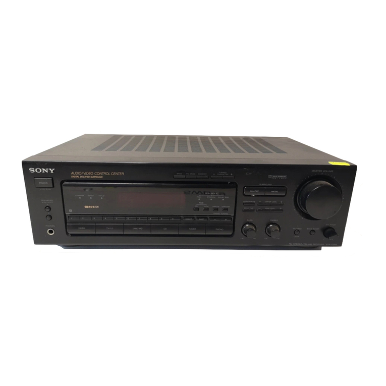
  9. Sony STR-D911 User manual

Sony STR-D911 User manual

FMStereo/FM-AM
Receiver
Operating Instructions
STR-D911
STR-D711
©1993 by Sony Corporation
To prevent fire or shock hazard, do not
expose the unit to rain or moisture.
RISK OF ELECTRIC SHOCK
DO NOT OPEN
CAUIlON: IOREDUCE IHI_RISKOFELI,CIRICSHOCK,
DO NOT REMOVE COVER (OR BACK).
NO USER-SERVICEABLE PARTS INSIDE.
REFER SERVICING TO QUALIFIED SERVICE PERSONNEL.
This symbol is intended to alert the user to
the presence of uninsulated "dangerous
voltage" within the product's enclosure that
may be of sufficient magnitude to constitute
a risk of electric shock to persons.
This symbol is intended to alert the user to
the presence of important operating and
maintenance (servicing) instructions in the
literature accompanying the appliance.
Note to CATV system installer
This reminder is provided to call the CATV system
installer's attention to Article 820-40 of the NEC that
provides guidelines for proper grounding and, in
particular, specifies that the cable ground shall be
connected to the grounding system of the building, as
close to the point of cable entry as practical.
Owner's Record
The model number is located on the rear exterior and serial
number is on the rear. Record the serial number in the
space provided below. Refer to these numbers whenever
you call upon your Sony dealer regarding this product.
Model No. STR-D911
Model No. STR-D711 Serial No.
Serial No.
INFORMATION
This equipment has becrl tested and lou, _dto uul_ply with
the limits for a Class B digital device, pursuant to Part 15 of
the FCC Rules.
These limits are designed to provide reasonable protection
against harmful interference in a residential installation.
This equipment generates, uses, and can radiate radio
frequency energy and, if not installed and used in
accordance with the instructions, may cause harmful
interference to radio communications. However, there is no
guarantee that interference will not occur in a particular
installation. If this equipment does cause harmful
interference to radio or television reception, which can be
determined by turning the equipment off and on, the user is
encouraged to try to correct the interference by one or
more of the following measures:
Reorient or relocate the receiving antenna.
-- Increase the separation between the equipment and
receiver.
Connect the equipment into an outlet on a circuit
different from that to which the receiver is connected.
-- Consult the dealer or an experienced radio/TV
technician for help.
CAUTION
You are cautioned that any change or modifications not
expressly approved in this manual could void your authority
to operate this equipment.
WARNING
To prevent shock hazard, do not insert the plug cut off from
the mains lead into a socket outlet. This plug cannot be
used and should be discarded.
If the plug supplied with this appliance has detachable fuse
cover, be sure to attach the fuse cover after you change the
fuse. Never use the plug without the fuse cover.
Ifyou should lose the fuse cover, please contact your
nearest Sony service station.
For the customers in Canada
CAUTION :
I O PREVENT ELECTRIC SHOCK, DO NOT USE THIS
POLARIZED AC PLUG WITH AN EXTENSION CORD,
RECEPTACLE OR OTHER OUTLET UNLESS THE
BLADES CAN BE FULLY INSERTED TO PREVENT
BLADE EXPOSURE.
This apparatus complies with the Class B limits for radio
noise emissions set out in Radio Interference Regulations.
2
Introduction
Overview ................................................................. 4
Precautions ......................................................................... 4
Chapter I Getting Started
Unpacking ........................................................................... 5
Choosing a good location............................................. 5
Checking the supplied accessories...............................5
Selecting theAM tuninginterval
(exceptforAustralian model).......................................5
Insertingthebatteries intothe remotecommander..... 5
Hookingup thesystem....................................................... 6
Connecting audioequipment.........................................6
Connecting videoequipment........................................ 7
Connecting an FM antenna........................................... 7
Connecting an AM antenna.......................................... 7
Connecting theantennaground ....................................7
Connecting speakersystems........................................ 8
Connecting totheAC poweroutlet................................8
Identifying the partsand controls....................................... 9
Frontpanel .....................................................................9
Remotecommander
(exceptfor theSTR-D911for Canadian model) ........10
Chapter 2 Basic Operations
Operating withthe remotecommander.............................11
Changing thesettingsofthe FUNCTIONbuttons........11
Adjusting basicaudiocontrols..........................................12
Adjusting volume..........................................................12
Adjusting left and rightsoundbalance........................12
Adjusting tonefrom thefront speakers........................12
Reinforcingthebass ....................................................12
Selecting thespeaker system......................................12
Selecting a programsource................................................
Labelingtheprogramsource.......................................13
Toturnoffthe powerat thedesiredtime
(Thesleep timerfunction) ..........................................13
Receivingbroadcasts........................................................14
Tuningina stationdirectly (Directtuning)...................14
Scanningstations automatically(Automatictuning).. 15
Presettingstations(Stationpreset) ..............................16
Tuningin a preset station (Presettuning)................... 17
Labelingthe presetstations (Stationindex)................ 18
Selecting astation amongthe preset stations inthe
index(Index tuning).................................................. 19
ReceivingFM simulcast IV programs.........................19
Recordingan audiosource .............................................. 20
Recording ontoanaudiotape deck or DAT deck ...... 20
Tape dubbing ...............................................................20
Editinga videosource ...................................................... 21
Videotapedubbing .....................................................21
Adding new sound on avideotapeduring video
editing........................................................................22
Chapter 3 Advanced Operations
Getting ready for Dolby surround sound ......................... 24
Placement of speakers and selecting the
PRO LOGIC MODE .................................................... 24
Adjusting the speaker volume ...................................... 25
Adjusting the surround sound ............................................ 26
Adjusting the delay time of the rear speakers ............. 26
Adjusting the surround effect ....................................... 26
Sound field settings ........................................................... 27
Available type of effects ............................................... 27
Adjusting the tone controls .......................................... 28
Adjusting the sound field programs ............................. 28
Calling up the sound field setting ................................ 29
Linking the sound field memory to preset
stations or program source ........................................ 29
Chapter 4 Other Information
Troubleshooting guide ..................................................... 30
Specifications ..................................................................... 32
Quick reference ................................................................ 34
3
he S [R-D911/13711 is an _M Stereo/FM-AM receiver and
audio/video control center.
You can enjoy various audio/video program sources with
this unit.
TV/videe programs
•You can enjoy TV or CATV programs with FM simulcast.
•Sounds from various audio program sources can be
added on video tapes during editing.
Tuner
• Precise tuning is ensured by a quartz locked digital
synthesizer.
• Station Index system allows you to tune into a station
quickly.
DOLBY PRO LOGIC
In the DOLBY SUR or THEATER mode, the Dolby* Pro Logic
can be selected. The Dolby Pro Logic Surround Decoder
has the same functions for playback as movie theaters and
gives a theater4ike experience in your listening room,
naturally reproducing the audio sound field.
* Manufactured under license from Dolby Laboratories Licensing
Corporation. Additionally licensed under one or more of the
following patents: U.S. number 3,959,590: Canadian numbers
1,004,603 and 1,037,877. "DOLBY", "Pro Logic", and the double-
D symbol are trademarks of Dolby Laboratories Licensing
Corporation.
Sound field (combination of digital delayed surround
and tone controls)
• 7 recommended sound field programs (DOLBY SUR,
THEATER, LIVE, HALL, DANCE, SIMULATED,
ACOUSTIC) are preset in the factory for easy use. You
can also store up to 7 settings you created in the memory.
• Combined use of the sound field programs and the preset
stations or program source allow you to enjoy broadcast
or program source listening immediately with the
memorized 7 settings of sound field (DOLBY SUR,
THEATER, LIVE, HALL, DANCE, SIMULATED,
ACOUSTIC).
Digital surround sound system (STR-D911 only)
The STR-D911 is equipped with a Digital Signal Processor.
All of 7 types of surround effect -- DOLBY SUR, THEATER,
LIVE, HALL, DANCE, SIMULATED and ACOUSTIC have
been preset.
Remote commander
The supplied remote commander allows you to remotely
control this receiver and the equipments connected to the
receiver.
For the instruction of the remote commander for Canadian
model, see the operating instructions of the separate
volume.
On safety
•For the U.S.A. al_d cal_adial_ iHodels, operate the unit
only on 120 V AC, 60 Hz.
For Australian model, operate the unit only on 240 V AC,
50 Hz.
• Should any solid object or liquid fall into the cabinet,
unplug the unit and have it checked by qualified
personnel before operating it any further.
• Unplug the unit from the wall outlet if it is not to be used
for an extended period of time. To disconnect the cord,
pull it out by grasping the plug. Never pull the cord itself.
• One blade of the plug is wider than the other for the
purpose of safety and will fit into the power outlet only
one way. If you are unable to insert the plug fully into the
outlet, contact your dealer. (except for Australian model)
• AC power cord must be changed only at the qualified
service shop.
• This unit is not disconnected from the AC power source
as long as it is connected to the mains outlet, even if the
unit itself has been turned off.
On operation
Before making program source connections, be sure to
turn the power switch off and unplug the unit.
On cleaning the cabinet
Clean the cabinet, panel and controls with a soft cloth
lightly moistened with mild detergent solution. Do not use
any type of abrasive pad, scouring powder, or solvent such
as alcohol or benzine.
For the customers in the U.S.A.
For detailed safety precautions, see the "IMPORTANT
SAFEGUARDS" leaflet.
If you have any question or problem concerning your unit,
please consult your nearest Sony dealer.
4
To prevent internal heat buildup in the unit,
place the unit in a location with adequate air circulation.
Do not install the unit:
•near heat sources such as radiators or air ducts.
• in a place subject to direct sunlight, excessive dust,
mechanical vibration or shock.
Do not place anything on top of the cabinet.
The top ventilation holes must be unobstructed for the
proper operation of the unit and to prolong the life of its
components.
Do not throw away the carton and packing material!
Itwillbe an ideal container when transporting thesystem for
repairwork,etc.
The AM tuning interval is preset to 10 kHz. To use the
receiver where the frequency allocation system is based on
a 9 kHz interval, make the following adjustments.
1 Turn on the power and tune in any AM station.
2Turn off the power.
3Press the POWER button while pressing the INDEX
SELECT/TUNING + button.
To reset the AM tuning interval, repeat the above steps.
Caution
Whenthe intervalischanged, all preset stations whichyou
have memorizedwillbe erased.After changingtheinterval,
besureto presetthe stationsagain.
After unpacking, check that the following accessories are
present.
• FM wire antenna ........................................................... (1)
• AM loop antenna .......................................................... (1)
• Remote commander ..................................................... (1)
•Sony batteries SUM-3 (NS) .......................................... (2)
Before operating remote commander, install the batteries as
shown.
1Open the cover. 2Insert two size AA (R6)
batteries with correct
polarity.
To avoid damage caused by battery leakage and
corrosion
When the commander will not be used for a long time,
remove the batteries.
Battery life
Normal operationcan be expected about a half year using
Sony SUM-3 (NS), and a yearusingSonyAM-3 (NW)
alkalinebatteries.
Whenthe batteriesare run down,theremotecommander
willnotoperatetheunit. In thiscase, replace batteries with
new ones.
5
At first, this section describes about the connection with the othu_ equipments, the antenna
connection, speaker connection and then the AC power connection.
• Do not connect the power cord to an AC outlet nor press the POWER switch before
accomplishing all other connections.
• The cable connectors should be fully inserted into the jacks• Loose connection may cause
hum and noise.
• Jacks and plugs of the connecting cord are color-coded as follows:
Red jacks and plugs: For the right channel of audio signals
White jacks and plugs: For the left channel of audio signals
Yellow jacks and plugs: For video signals
Receiver
White
L(_)*'*_=_
R @*-_,-==_
Red
Other equipment
White
Red
Turntable
CD player
_iirl ,-ii- _
_1__
F]
to OUTPUT
to OUTPUT
'3-
@I@ © F_ONIMR_
@I_ _
to LINE OUT
to LINE IN
to LINEOUT
to LINE IN
iTape deck 2
Tape deck 1 J
IDAT deck IN
'to LINE OUT
6
I VCR 3
to VIDEO 3 INPUT on
the front panel
(STR-D911 only)
VCR 2! LD player
I Monitor TV I
.._ Z°Y'D2°JN-I "
;l;;i
6 I@1@1@@1@@ ,_1,__ I@01
F 1 toAUD,O/
VIDEO OUT
to AUDIO/ 1
t to AUDIO/VIDEO OUT VIDEO IN
,L
VCR 1
_]_ h,l_lr_,_'3
Though the wire antenna is supplied with this unit, the
higher quality sound will be obtained with the 75-ohm
coaxial cable.
rFor normal use
Supplied wire
- antenna
For higher quality sound
F_ 75-ohm coaxial cable
(optional)
[_j [l_ _[I-]?_IT_I
_ _ 300-ohm twin-lead
(optional)
_.. • J
The AM broadcast is enough received with the supplied AM
loop antenna. However, the connection of insulated wire is
also available for areas with difficult AM reception.
Supplied AM
loop antenna
ust the
•,,. .,, direction.
For areas with difficult AM reception
In areas with troubled reception, connect a 6 to 15-meter
(20 to 50-feet) insulated wire to the AM antenna terminal.
Extend this out of doors if possible, keeping the greater
portion horizontal.
(There is no need to disconnect the supplied antenna.)
To prevent hum, connect the ground wire to ANTENNA
ground terminal (#n).
When an outdoor antenna is installed, be sure to connect
the ground wire for lightning protection.
7
Front, rear and center speakers can be connected to this unit.
Approx. 15 mm
(9/16inches) Front Front
speaker (R) speaker (L)
@©@
I©1¢1@@1@©1@1©@1#¢1
o I@1@1@@1@©1@1@@1@@1
F ]
Rear
speaker (R) Rear
speaker (L)
I I
I I
I I
Center
speaker
IMPEDANCE selector
(STR-D911 only)
,,,1_to the second
front speaker
system
On the IMPEDANCE selector (STR-D911 only)
The STR-D911 has the IMPEDANCE SELECTOR for front
speakers.
When using the front speakers having nominal impedance
from 4 ohms or higher, set to the 4 £',.position.
When using the front speakers having nominal impedance
from 8 ohms or higher, set to the 8 .O.position.
Note
Use the front speakers having nominal impedance of more
than 8 ohms in the SURROUND mode.
Note
When connecting the speaker cord to the speaker terminal,
make sure that the polarity (+ and -) of the speaker cord is
correct. If the polarity is reversed at either speaker, the
sound will be distorted and will lack bass,
Connect the AC power cord to the wall outlet last of all.
By connecting the power cord of the other audio equipment
to SWITCHED AC OUTLET, this unit can supply the power
source to the other audio equipment.
Caution
Be careful that the total power consumption of each
equipment connected to the outlets on the receiver does not
exceed 120 watts (for U.S.A. and Canadian models) or 100
watts (for Australian model).
Do not connect electrical home appliances such as an
electric iron, fan, TV, or other high-wattage equipment to
these outlets.
8
This illustration shows the STR-D911. The STR-
D711 is not equipped with the EDIT VIDEO and
VIDEO 3 buttons and VIDEO 3 INPUT jacks.
[] POWER switch
[] EDIT VIDEOIAUDIO buttons (See pages 21, 22, 23.)
(EDIT VIDEO button: STR-D911 only)
[] TUNING LEVEL (See page 15.)
[] STANDBY indicator
(The STANDBY indicator lights up when the power cord
is connected.: STR-D911 for Australian model only)
[] Remote sensor
[] INDEX SELECT/TUNING +1- buttons
(See pages 15, 19.)
[] PRESET TUNING +/- buttons (See pages 17, 19)
[] SOUND FIELD LINK button (See page 29.)
[] SOUND FIELD ON/OFF button (See page 25.)
[] PRO LOGIC MODE button
(See pages 24, 25.)
[] Display window
[] SOUND FIELD buttons (See pages 26, 27, 28, 29.)
[] CURSOR MODE indicators
[] CURSOR MODEoperation buttons (See pages 13, 18,
25, 26, 28.)
_nnn_CURSOR MODE button (See pages 13, 18, 25, 26, 28.)
[] TONE ON/DEFEAT button (See page 28.)
[] DBFB button (See page 12.)
[] MASTER VOLUME control (See page 12.)
[] BALANCE control (See page 12.)
[] VIDEO 3 INPUT jacks (STR-D911 only)
[] MUTING button and indicator (See pages 12.)
[] DISPLAY button (See pages 15, 18, 19.)
[] FM MODE button (See page 14.)
[] DIRECT button (See page 14.)
[] FM/AM button (See pages 14, 15o)
[] MEMORY button (See page 16.)
[] Numeric buttons (See pages 14, 16, 17, 19.)
[] SHIFT button (See pages 16, 17.)
[] Function selectors and TAPE 2 MONITOR button and
indicator (VIDEO 3 button: STR-D911 only)
(See pages 12, 20.)
[] HEADPHONES jack
[] SPEAKERS selector (See page 12.)
9
_ C_ CE_ CJ CZ
_ C3E] _ C
O00
0001_
ooo/
oo_qo_ou,-
0 © c:n c:nr--
0 mr-
[] Receiver control section
FUNCTION buttons
DAT, CD, TUNER, PHONO, VIDEO 1, VIDEO 2, VIDEO
3, TAPE: The each function is selected and the each
unit enters its operating mode automatically.
SYSTEM OFF: Turns off the power of the whole system.
SOUND FIELD buttons
USER/PRE: This button does not function.
MODE: Selects the sound field mode.
ON/OFF: Turns on/off the sound field system.
BAND: This button does not function.
EQ: Turns on/off the setting of TONE controls.
T. (test) TONE: Generates a pink noise signal that is
sent in succession to each speaker.
CURSOR MODE: Select CURSOR MODE.
CURSOR operating buttons
REAR LEVEL +/- buttons: Control the volume of rear
speakers (surround level).
CENTER LEVEL +1- buttons : Control the volume of
center speaker (surround level).
DBFB button: Turns on/off the DBFB (Dynamic Bass
Feedback).
MUTING button: Mutes the sound.
MASTER VOL +/- buttons: Control the receiver
volume.
SLEEP: Set to tl_e SLEEP timer mode. In this mode, the
unit is automatically turned off after the designated
time. (page 13)
Note
THe VIDEO 3 button functions only for the STR-D911.
10
Other equipment control section
The operative buttons are changed according to the
function mode and the setting of the SYSTEMfl-V
selector.
Numeric buttons (1 to 0): Designate the number.
>10: Designate the number more than 10.
ENTER: Press after designating the TV/VCR channel.
TVNIDEO selector: Selects the IV program to see : TV
or VIDEO.
ANT TV/VTR button: Selects the output signal from the
antenna terminal on the VCR, either a TV signal or
VCR programs.
SHIFT: Select the memory page (A, B or C) only in the
TUNER mode.
CH/PRESET +/- buttons: Select a preset station of tuner
or a preset channel of TV/VCR.
INDEX: Select another index station.
,<_/IH_: fast winding/Manual search
e: Recording (Press • and <or • at the same time.)
4/•: Play
B: Stop
I1: Pause
t,<_/_: Locates a desired selection.
D (disc) SKIP: Disc skip (for a CD player equipped
with a multi-disc changer)
SELECT: Changes the settings of the FUNCTION
buttons.
VISUAL POWER: Turns on/off the power of TV, VCR and
LD player.
[] SYSTEM/TV mode switch
In TV mode (When setting the SYSTEM/TV selector
to Tv.)
Only MUTING, MASTER VOL +/- and the operative
buttons in TV section on the list described on the next
page can be used.
Beforeoperatingtheequipmentswiththeremote
commander,besuretosetthereceivertothedesiredmode
bypressingoneoftheFUNCTIONbuttons.
FUNCTION to be
pressed
The FUNCTION buttons are factory set in the following list.
Operating equipment
DAT DAT deck
CD CD player
TUNER Tuner
PHONO (The receiver enters the PHONO mode.)
VIDEO 1 Betamax VCR (VCR 1)
VIDEO 2 LD player
VIDEO 3 8 mm VCR (VCR 2)
TAPE Tape deck A
• When VIDEO 1, 2 or 3 is pressed, the power of the
selected video equipment and TV is turned on.
Operating the equipment
1 Press the desired FUNCTION.
2Press .< (only for tape deck) or m,-to start playback.
Illj n_-I,[! il ij; I iiFJl-!:_ ill hi, [--I.) Irl i]_l1:11J _[q i [0] _I :gri |(.] it.!
With the SELECT button, you can replace the functions
stored in the FUNCTION buttons.
To change the settings of the FUNCTION buttons
1Press one of the FUNCTION buttons to be stored.
2Press SELECT by using the pointed tool.
3Press 1 to 9 button to select the desired function within 30
seconds.
To reset to the initial state, press the >10 button.
With the numeric buttons from 1to 9, the each function
can be selected as described below:
Numeric buttons
to be pressed
1
2
3
4
5
6
7
8
9
Note
The function to be selected
CD player
DAT deck
DECK A
DECK B
TV
LD player
VTR 1
VrR 2
VTR 3
The 0 and ENTER buttons do not function.
List of operative buttons in SYSTEM mode (When setting
the SYSTEM/TV selector to SYSTEM
OperatingTUNER CD DAT
equipment DECK TV LDP VTR 1,
A,B 2,3
1•••-- • • •
2• • • -- • • •
3 • • • -- • • •
4 • • • -- • • •
5 • • • -- • • •
6 • • • -- • • •
7 • ••-- • • •
8 • • • -- • • •
9• • • -- • • •
0 • • • -- • • •
>10 -- • -- -- -- •--
ENTER .... •••
SHIFT • ......
TVNIDEO .... •o* o*
ANT TV/ ...... •
VTR
CH
PRESET • -- -- -- •__ •
+I-
INDEX • ......
D.SKIP -- •.....
-- • • • -- • •
41+0 -- -- __ • __ __ __
Ira.,+O-- -- • • -- __ •
II -- • • • -- • •
•4Hi -- __ __ • __ __ __
jj,,,, -- • • • -- • •
•-- •• • _• •
VISUAL .... •••
POWER
•'The button is operative.
--: The button is not operative.
•* The button can operate TV.
Note
To operate the unit correctly, the function mode of the
receiver should be same with that of the remote
commander. So, be sure to press the desired FUNCTION
button at first and then the operative button.
11
You can enjoy superb sounds using the audio adjustment
functions as shown below.
MASTER
SPEAKERS TONE DBFB VOLUME
dip o=_'d.......... _, ® .
To adjust volume
Turn MASTER VOLUME.
To reduce the sound to a low level temporarily (- 20 dB
attenuation)
Press MUTING. The indicator lights up.
Press again to restore the same listening level as before.
Adjust BALANCE to correct stereo imaging, when the
speaker position is not symmetrical.
Press ACOUSTIC so that ACOUSTIC appears on the
dispaly and then press CURSOR MODE so that the TONE
indicator lights up. Press <:l or _>to select BASS or
TREBLE respectively and then press A or v to adjust the
level.
Press DBFB (Dynamic Bass Feedback) so that DBFB ON
appears on the display. Press again to turn off the effect so
that DBFB OFF appears on the display.
To drive speaker system A: Set SPEAKERS to A.
To drive speaker system B: Set SPEAKERS to B.
To drive both speaker systems A and B (series
connection): Set SPEAKERS to A + B.
For headphone listening: Connect headphones to
HEADPHONES and set SPEAKERS to OFF.
IMPORTANT
Speaker systems A and B are series connected. When
only one speaker system is connected, no sound can be
heard at the A + B position.
12
] ]
-O'WER-'4"ON ]
0II I I I I I
o []l I1I]III(ooo)
-! ' '
ITur table J
ICD player 1
ITape deck ] 2
1 DAT I
I VCR I
I LDplayer I
Select the program source.
What you select
Phono record
Radio Broadcast
Compact disc
DAT program
Taped program
Video program
"]°[[]F.... _ ..........
Press
PHONO
TUNER
CD
DAT
TAPE 1, TAPE 2 MONITOR
VIDEO 1, VIDEO 2/LD,
VIDEO 3 (STR-D911 only)
When a function selector is pressed, the indicator
of the function you have selected appears on the
display.
Select the function with the remote commander,
the power switches of both this receiver and the
selected equipment are turned on.
Start playback of the selected program.
You can input program sources under index names you
create (up to 11 characters); for example, PHONO, TUNER,
CD etc.
IPOWER --* ON I
1
0
0
I I
2 3
0IIIIIII III0
o o i])
Dt l _ I I I I I | I I
1
1Select the program source.
2
3
4
Press CURSOR MODE to select the INDEX
mode.
CURSOR MODE
The INDEX indicator lights up.
Create an index name.
re select a letter (A to Z) or number (1 to 9), press
z_or _7.
To change the position, press <] or D.
Repeat steps I to 3 for all other program
sources you want to assign an index name to.
If you input an already store source under any other
index name
Only the last selected index name will be valid. Each
program source can be stored under only one index name.
To switch the display mode between the original
function name display and created index name display
Each time the DISPLAY is pressed, the selected function
name (which corresponds to the function selector) and the
created index name are alternately displayed.
This function can be operated only with the remote
commander.
This receiver has the sleep timer function. With this
function, you can turn off the power automatically at the
desired time by designating the turn-off time.
Press SLEEP on the remote commander when the power is
on. Each time SLEEP is pressed, the designating time is
displayed in the following order: 2 hours --* 1 hour and 30
minutes -* 1 hour .-_ 30 minutes .-_ SLEEP OFF.
SLEEP
i
0 O i_
o O O00_i_
oO O Ol D
_:_0 0 02_
O O -_ _ c_
O ._.JcJ
_U
_r._l
L __
To change the turn-off time
1Press SLEEP and the remaining time is displayed.
2Press z_or _7to change the sleep time. The sleep time is
changed by 1 minute. It can be changed up to 5 hours.
To check the remaining time of the sleep timer
Press SLEEP. The remaining time is displayed.
13
IPOWER "* ON [ 4 -
1
1Press TUNER.
2
LTUNER 1
TUNER frequency appears on the display.
Select FM or AM.
Press DIRECT.
4Enter the frequency.
IT---I F_--I 13 II 4 I_ IT_I 71_
The entered frequency is displayed.
Example 1: FM 102.50 MHz Example 2: AM 1350 kHz
1 0 2 5 0 1 3 5
1,!
...:L ...... = =..JI ! ,L "j ":3E.... L."..
--*| ...... ;, .t.
14
To correct the entered frequency
Repeat steps 3 to 4.
For entering AM frequencies
You need not enter the last "0". (Except for Australian
model)
However, if you have changed the AM tuning interval to 9
kHz, enter all the digits.
If you enter a frequency not covered by the tuning
interval
The entered value is automatically rounded up or down to
the closest value covered by the tuning interval.
Tuning intervals for direct tuning are the followings:
FM: 50 kHz interval
AM: 10 kHz interval (changeable to the 9 kHz interval)
(See page 5)
9 kHz interval only for Australian model.
When the entered frequency does not exist in the
receivable frequency range
The entered digits blink as follows in the frequency display
area, and reception does not take place.
U.S.A. and Canadian models:
Up to 5 digits for FM or up to 3 digits for AM
Australian model:
Up to 5 digits for FM or up to 4 digits for AM
If this occurs, press DIRECT again, and enter the correct
frequency. The frequency range of the receiver is 87.50 to
108.0 MHz for FM, and 530 to 1710 kHz (U.S.A. and
Canadian models) or 531 to 1602 kHz (Australian model) for
AM.
When an FM stereo program is noisy
When the unit receives an FM stereo program, the STEREO
indicator lights on the display. If the stereo program is noisy,
press FM MODE to change the mode over the MONO. This
eliminates the stereo effect, but the noise will be greatly
reduced.
To return to the stereo mode, press FM MODE again.
Whenyoudonotknowthe|requencyofthestationtobe
received,proceedasfollows.
POWER .--,,ONJ
TUNING
LEVEL
4 2 3
oL__ ]i_
r 1
_ I I i, _lllr II
1Press TUNER.
TUNER frequency appears on the display.
2Select FM or AM.
3
4
Press DISPLAY.
The frequency appears on the display.
Press INDEX SELECT/TUNING + or-.
INDEX SELECT/TUNING
I/-
For a lower For a higher
frequency frequency
When a station is received, automatic tuning stops.
;;_ Repeat step 4 until the desired station is
received.
If the automatic scan stops frequently (for FM reception
only)
You can receive only the strong stations by pressing
TUNING LEVEL. HIGH appears on the display.
To receive all receivable stations again
Press TUNING LEVEL so that HIGH goes off.
15
A totalof30 FM/AM stations can be memorizedin any
desired sequence.
POWER --_ ON I 3
r_
0
0
ol
0I I II I I I I I I
o........ JJ_,L •
D[ I I I I , ,[, I _
41
1Press TUNER.
2
3
4
TUNER frequency appears on the display.
Tune in the desired station.
(See "Direct Tuning" or "Automatic Tuning" on
pages 14 and 15.)
Press MEMORY.
MEMORY appears on the display.
While MEMORY appears, select the memory
page (A, B or C).
Each time SHIFT is pressed, A, B or C is indicated
cyclically on the display.
5While MEMORY appears, press the desired
number.
[_--I r_--i _F---11_---1 IT--7 ,IF-
Repeat above steps for presetting other desired
stations.
Replacing a preset station
Preset another station on the number of thestation tobe
replaced.The previouslypresetstationwillbe erased.
16
There are two ways to perform the preset tuning.
In method A, the direct tuning, select by designating the
desired preset station number directly with the numeric
buttons. In method B, the scan tuning, select the preset
station with the PRESET TUNING +/- button.
lMethod A: Direct tuning I
POWER _ ON ] 3
r_
®
O
"°1
OIL I I I I I
O , II II
E]ll i i
2
©
I I I I I I 0
o @
1
1
2
3
Press TUNER.
TUNER J
5
TUNER frequency appears on the display.
Select the memory page (A, B, or C).
Each time SHIFT is pressed, A,B or C is
indicated cyclicallly on the display.
Designate the desired preset station number
with the numeric buttons.
5
I-MethodB:_ca.iu_
I POWER -" ON I 2
l_°1
o
oDI I L
II!IIIII I 1 I O
o @
1 I I ] ,i i (ooo)
i i
1Press TUNER.
2
TUNER
TUNER frequency appears on the display.
Select the desired preset station with PRESET
TUNING + or-.
PRESET TUNING
I/ 1
For a lower For a higher
preset number preset number
A1 _ AO _ -B1 _ BO
+ + +
_ CO.__.__ Ct -
IMPORTANT
The memorized station is maintained for approximately one
month even if the power cord is disconnected from the AC
power outlet. If they are erased, store the stations again.
17
You can divide preset stations under index names you
create (up to 5 characters). If you want to categorize the
preset stations by kinds of music, for example, create
indexes such as ROCK, JAZZ, etc.
IPOWER-" ONI 4 3
ol ©
0 I I I I I I I I I I I I I I€,
00_ I I I I I I I (ooo)
L_
1
2
Press TUNER.
TUNER frequency appears on the display.
Tune in the desired station with Preset Tuning.
3
4
Press CURSOR MODE to select the INDEX
mode.
CURSOR MODE _ (_
The INDEX indicator lights up.
Create an index name.
To select a letter (A to Z) or number (1 to 4), press
z_or _7.
To change the position, press <_or _>.
5 Repeat steps 2 through 4 for all other stations
you want to assign an index name.
If you store an already categorized station under any
other index name
Only the last selected category will be valid. Each station
can be stored under only one index name
To display the frequency and index name of preset
stations
Each time DISPLAY is pressed, frequency and index name
of the preset station are alternately displayed.
18
IPOWER .-_ ON 1 3 2
!- •
0I I l l I I I I I I I I I I
0 -JU_E __r
oE]t I i1 i i _ J l
It
oq
Cooo)
1Press TUNER.
2
TUNER J
TUNER frequency appears on the display.
Press DISPLAY to set to the index mode.
II1:_
3
When no index name is memorized, "no-index"
appears on the display.
Select the desired station.
•To select a station in the same index:
PRESET TUNING
I,- I +,,I
For lower channnel For higher channel
index station index station
• To select a index station other than the displayed
index station:
INDEX SELECT/tUNING
l
-- I +
iii I
5
PRESET TUNING
-'/- I +\1
For lower For higher
channel channel index
index station station
1
2
3
4
IPOWER-"owl
ImvtunerorVCRI3
VIDEO 1, 2
or3 IN _MON 2
ITOR
I VIDEO OUT
o{ O
O I I I I I ! I I II I "O
@ o ........................ =o ®
oo,, ,, I I Ill _ _
i 1
14 4
Select VIDEO 1, VIDEO 2/LD or VIDEO 3 (STR-
D911 only).
VIDEO 1, VIDEO 2/LD or VIDEO 3 appears on the
display.
According to video inputs connected to an
equipment to which the VHF antenna is connected.
Turn on the monitor TV.
Select the desired program on the TV tuner or
the VCR.
Select TUNER and tune in the FM simulcast TV
program on the receiver.
TUNER
?5
IV-_ r_---1 r_--7 I, II5 Ir_-7 F--
19
l =(:_.] _,ui[, [.]. I(._l nw_mr[.J[;-i _] _,_:iJ_/'_ :q[.]• DT_'_IllJ/:_'_:1. i_,'[_ [_'_'J_J
,=_ Audio signals
[POWER -.-* ON I
[]
1
oIll I, ,,_½_jj_½.
o ,_E
Da ii IiIi
__l L__J
0
E
to DAT or
TAPE 1, 2 OUT "[]- 1]"
Turntable
2IDAT or tape deck CD player 3
1 VCR I
4
I Select the desired program source with the
function selector.
For an FM/AM broadcast, tune in the desired station
2Set the tape (DAT) deck in the recording mode.
Start playback of the selected program source.
Note on recording
For TAPE 1, 2 and DAT REC OUT jacks, the settings of
SOUND FIELD and DBFB do not have any effect on
recording.
Monitoring the recorded sound
If you have connected a 3-head tape deck to the TAPE 2
jacks, you can monitor the recording results. While
recording or dubbing, press TAPE 2 MONITOR so that the
TAPE 2 MONITOR indicator lights up. To listen to the source
sound again, press the button again so that the indicator
goes off.
=# Audio signals
I POWER
G
¢
O
to TAPE 2 OUT
Tape deck 2 /
(for recording) J
--*ONI 3
roi ]
OII I I IIIII I I I I I I I
o Fac_"_ _
O[ i i , f [[II
lto TAPE_
£I (or DAT) IN
I
Tape deck 1 or
DAT deck
(for playback)
1
2
Insert the recorded tape into tape deck I (or the
DAT deck).
Insert a blank tape into tape deck 2 and adjust
the recording level.
3
4
Press TAPE 1 or DAT to select the deck for
playback.
Set tape deck 2 in the recording mode and then
start playback of the tape (or the DAT) on tape
deck I (or the DAT deck).
Dubbing will start.
Note on tape dubbing
Tape dubbing is possible only in the following directions:
From
(playback deck)
Tape deck
;connected to
TAPE 1 IN
DAT deck
connected to
DAT IN
To
(Recording deck)
Tape deck connected to TAPE 2 OUT
DAT deck connected to DAT OUT
Tape deck connected to TAPE 1 or 2
OUT
Press the function selector according to the playback deck.
20

This manual suits for next models

1

Other Sony Receiver manuals

Sony AVD-S50 User manual

Sony

Sony AVD-S50 User manual

Sony STR-DH700 User manual

Sony

Sony STR-DH700 User manual

Sony STR-D2090 User manual

Sony

Sony STR-D2090 User manual

Sony STR-DA7100ES - Fm Stereo/fm-am Receiver User manual

Sony

Sony STR-DA7100ES - Fm Stereo/fm-am Receiver User manual

Sony STR-DE475/K402 User manual

Sony

Sony STR-DE475/K402 User manual

Sony STR-DA3600ES - Multi Channel Av Receiver User manual

Sony

Sony STR-DA3600ES - Multi Channel Av Receiver User manual

Sony STR-DH510 - 10str Hifi User manual

Sony

Sony STR-DH510 - 10str Hifi User manual

Sony HBD-E370 User manual

Sony

Sony HBD-E370 User manual

Sony ICF-PRO70 User manual

Sony

Sony ICF-PRO70 User manual

Sony STR-DH820 User manual

Sony

Sony STR-DH820 User manual

Sony STR-DE725 - Fm Stereo/fm-am Receiver User manual

Sony

Sony STR-DE725 - Fm Stereo/fm-am Receiver User manual

Sony HCD-SR4W User manual

Sony

Sony HCD-SR4W User manual

Sony STR-DH510 - 10str Hifi User manual

Sony

Sony STR-DH510 - 10str Hifi User manual

Sony STR-DH700 User manual

Sony

Sony STR-DH700 User manual

Sony AC-110MD User manual

Sony

Sony AC-110MD User manual

Sony STR-DA2400ES User manual

Sony

Sony STR-DA2400ES User manual

Sony HCD-SV2D User manual

Sony

Sony HCD-SV2D User manual

Sony STR-DG520 User manual

Sony

Sony STR-DG520 User manual

Sony STR-DA2800ES User manual

Sony

Sony STR-DA2800ES User manual

Sony HCD-GZR9D User manual

Sony

Sony HCD-GZR9D User manual

Sony VGP-MR200 - VAIO RoomLink Network Media... User manual

Sony

Sony VGP-MR200 - VAIO RoomLink Network Media... User manual

Sony STR-DH710 - 10str Hifi User manual

Sony

Sony STR-DH710 - 10str Hifi User manual

Sony HCD-HDX285 - Dvd Home Theater System User manual

Sony

Sony HCD-HDX285 - Dvd Home Theater System User manual

Sony STR-DA2000ES - Fm Stereo/fm-am Receiver User manual

Sony

Sony STR-DA2000ES - Fm Stereo/fm-am Receiver User manual

Popular Receiver manuals by other brands

Kenwood IR-9991 instruction manual

Kenwood

Kenwood IR-9991 instruction manual

Topmodel XPower R4-B user manual

Topmodel

Topmodel XPower R4-B user manual

Comar Systems NMEA-2-WIFI user manual

Comar Systems

Comar Systems NMEA-2-WIFI user manual

Lectrosonics SRA5P instruction manual

Lectrosonics

Lectrosonics SRA5P instruction manual

Onkyo TX-NR1000 instruction manual

Onkyo

Onkyo TX-NR1000 instruction manual

Wegener UNITY 550 user manual

Wegener

Wegener UNITY 550 user manual

Denon AVR-3803 Control protocol

Denon

Denon AVR-3803 Control protocol

JVC KW-AVX900EU Service manual

JVC

JVC KW-AVX900EU Service manual

Yamaha RXA830 Quick manual

Yamaha

Yamaha RXA830 Quick manual

Microwave Radio MRX4000 Operator's guide

Microwave Radio

Microwave Radio MRX4000 Operator's guide

Onkyo TX-8160 instruction manual

Onkyo

Onkyo TX-8160 instruction manual

JVC RX-7020VBK Service manual

JVC

JVC RX-7020VBK Service manual

X10 PM5900 Installation and operating instructions

X10

X10 PM5900 Installation and operating instructions

Icom IC-R7000 instruction manual

Icom

Icom IC-R7000 instruction manual

Elk Products ELK-M1XRF319 installation manual

Elk Products

Elk Products ELK-M1XRF319 installation manual

Meinberg GNS165DHS manual

Meinberg

Meinberg GNS165DHS manual

Yamaha YBA-11 user manual

Yamaha

Yamaha YBA-11 user manual

DK Digital AVR-500 owner's manual

DK Digital

DK Digital AVR-500 owner's manual

manuals.online logo
manuals.online logoBrands
  • About & Mission
  • Contact us
  • Privacy Policy
  • Terms and Conditions

Copyright 2025 Manuals.Online. All Rights Reserved.