Sony STR-WX5 User manual

STR-WX5
E Model
Australian Model
Tourist Model
SERVICE MANUAL
FM STEREO/FM-AM RECEIVER
MICROFILM
SPECIFICATIONS
STR-WX5 is the tuner and amplifier
section in MHC-WX5.
Amplifier section
The following measured at AC 120, 220, 240V 50/60Hz
DIN power output (Rated) (FRONT)
120 + 120W (6 Ωat 1kHz DIN)
Continuous RMS power output (Reference)
150 + 150 W
(6 Ωat 1kHz, 10% THD)
Inputs MD/VIDEO 1 IN (phono jacks): voltage
450/250mV, impedance 47kΩ
AV INPUTAUDIO (phono jacks):
voltage 250mV, impedance 47kΩ
MIX MIC (phone jack): sensitivity 1mV,
impedance 10kΩ
Output MD/VIDEO 1 OUT (phono jacks):
voltage 450/250mV, impedance 1kΩ
PHONES (stereo phone jack): accepts
headphones of 8Ωor more.
FRONT SPEAKER:
accepts impedance of 6 to 16Ω
REAR SPEAKER:
accepts impedance of 16Ω
SUPER WOOFER:
Voltage 1V, impedance 1kΩ
Video section
Inputs AV INPUT VIDEO (phono jack): 1Vp-p,
75Ω
Outputs MONITOR OUT (phono jack): 1Vp-p,
75Ω
Tuner section
FM stereo, FM/AM superheterodyne tuner
FM tuner section
Tuning range 87.5 – 108.0MHz
Antenna terminals 75Ωunbalanced
Intermediate frequency 10.7MHz
AM tuner section
Tuning range
Latin America models: 530 – 1,710kHz (10kHz step)
531 – 1,710kHz (9kHz step)
Middle Easten models: 531 – 1,602kHz(with the MW interval set at
9kHz)
5.95 – 17.90MHz (with the SW interval set
at 5kHz)
Australian, Israel, and Thai models :
531 – 1,602kHz(with the AM tuning
interval set at 9kHz)
530 – 1,710kHz (with the AM tuning
interval set at 10kHz)
Other models: MW :
531 – 1,602kHz(with the MW tuning
interval set at 9kHz)
530 – 1,710kHz (with the MW tuning
interval set at 10kHz)
SW :
5.95 – 17.90 MHz (with the SW tuning
interval set at 5kHz)
Intermediate frequency 450kHz
Antenna AM loop antenna
External antenna terminal
— Continued on next page —
w
w
w
.
x
i
a
o
y
u
1
6
3
.
c
o
m
Q
Q
3
7
6
3
1
5
1
5
0
9
9
2
8
9
4
2
9
8
T
E
L
1
3
9
4
2
2
9
6
5
1
3
9
9
2
8
9
4
2
9
8
0
5
1
5
1
3
6
7
3
Q
Q
TEL 13942296513 QQ 376315150 892498299
http://www.xiaoyu163.com

2
TABLE OF CONTENTS
1. GENERAL ........................................................................... 3
2. DISASSEMBLY
2-1. Sliding Panel Assembly ······················································ 9
2-2. Level Slider ········································································ 9
3. SERVICE MODE .............................................................. 5
4. DIAGRAMS
4-1. Circuit Boards Location ·················································· 9
4-2. Block Diagrams
• Main Section································································ 10
• Power Section ······························································ 11
4-3. Printed Wiring Board Main Section ························· 12
4-4. Schematic Diagram Main (1/2) Section ························· 13
4-5. Schematic Diagram Main (2/2) Section ························· 14
4-6. Schematic Diagram AV/Mic Section······························ 15
4-7. Printed Wiring Board AV/Mic Section ··························· 15
4-8. Schematic Diagram Power Amp Section ······················· 16
4-9. Printed Wiring Board Power Amp Section····················· 17
4-10. Schematic Diagram Display Section ······························ 18
4-11. Printed Wiring Board Display Section ··························· 19
4-12. Schematic Diagram Sliding Panel Section ····················· 20
4-13. Printed Wiring Board Sliding Panel Section ·················· 21
4-14. Printed Wiring Board Trans Section······························· 22
4-15. Schematic Diagram Trans Section ································· 23
4-16. IC Block Diagrams··························································· 24
4-17. IC Pin Function ································································ 26
5. EXPLODEDVIEWS
6-1. Case and Sliding Panel Section ........................................ 29
6-2. Front Panel Section .......................................................... 30
6-3. Slide Mechanism Section ................................................. 31
6-4. Circuit Boards and Back Panel Section............................ 32
7. ELECTRICAL PARTS LIST ........................................ 33
LABEL MODEL NUMBER
No.
MODEL IDENTIFICATION
— BACK PANEL —
EXCEPT Israel, Thai model 4-900-848-0π
Israel, Thai model 4-900-848-1π
MODEL PART No.
General
Power requirements
Australian model: 240V AC, 50/60Hz
Israel and Thailand models:
220V AC, 50/60Hz
Other models: 120V or 220V or 230 – 240, 50/60Hz
Adjustable with voltage selector
Power consumption 290W
Dimensions (w/h/d) Approx. 288 ×205 ×375mm
Mass Approx. 7.8kg
Design and specifications are subject to change without notice.
w
w
w
.
x
i
a
o
y
u
1
6
3
.
c
o
m
Q
Q
3
7
6
3
1
5
1
5
0
9
9
2
8
9
4
2
9
8
T
E
L
1
3
9
4
2
2
9
6
5
1
3
9
9
2
8
9
4
2
9
8
0
5
1
5
1
3
6
7
3
Q
Q
TEL 13942296513 QQ 376315150 892498299
http://www.xiaoyu163.com

3
Front Panel
SECTION 1
GENERAL
11/u (Power) button
2SLIDING SENSOR window
3MOVIE indicator
4MUSIC indicator
5GAME indicator
6PLACE indicator
7P FILE indicator
8TUNER/BAND button
9STEREO/MONO button
0MEMORY button
qa AUTO indicator
qs OPEN/CLOSE button
qd KARAOKE PON/MPX button
qf MIC LEVEL knob
qg MIX MIC jack (EXCEPT JE model)
MIC 1 jack (JE model)
qh GROOVE button and indicator
qj VOLUME knob
qk EFFECT ON/OFF button and indicator
ql P FILE button
w; PLACE button
wa GAME button
ws MUSIC button
rf VIDEO (AV INPUT (VIDEO 2)) jack
rg AUDIO-L (AV INPUT (VIDEO 2)) jack
rh AUDIO-R (AV INPUT (VIDEO 2)) jack
rj SURROUND +/– buttons
rk DBFB +/– buttons
rl 63Hz +/– buttons
t; 250Hz +/– buttons
ta 1kHz +/– buttons
ts 4kHz +/– buttons
td 16kHz +/– buttons
tf NAME IN button
tg DELETE button
th CHAR button
tj INSERT button
tk OPEN SENSOR ON/OFF button
tl EQ MEMORY button
• Abbreviation
JE : Tourist model.
wd MOVIE button
wf ENTER/NEXT button and indicator
wg )+ button and indicator
wh =CMULTI JOG STATION c
+dial
wj 0– button and indicator
wk CD EDIT button
wl CD PLAY MODE button
e; CD REPEAT button
ea NON-STOP button and indicator
es FLASH button
ed LOOP button
ef DBFB button
eg DSP REVERB button and indicator
eh DSP DELAY button and indicator
ej PHONES jack
ek CLOCK/TIMER SET button
el TIMER SELECT button
r; FUNCTION button
ra DISPLAY/DEMO button
rs MIC 2 jack (JE model)
rd ECHO LEVEL knob
(JE model)
1
234567
8
9
0
qa
qs
qd
qf
qg
qhqjqk
qlw;wawswd
wfwgwhwjwkwle;
eaesedef
egeh
ej
ek
el
r;
ra
EXCEPT JE
rf rg rh rj rk rl t; ta ts td tf tgth tjtk tl
rd
rs
qf
qg
JE MODEL
w
w
w
.
x
i
a
o
y
u
1
6
3
.
c
o
m
Q
Q
3
7
6
3
1
5
1
5
0
9
9
2
8
9
4
2
9
8
T
E
L
1
3
9
4
2
2
9
6
5
1
3
9
9
2
8
9
4
2
9
8
0
5
1
5
1
3
6
7
3
Q
Q
TEL 13942296513 QQ 376315150 892498299
http://www.xiaoyu163.com

4
SECTION 2
DISASSEMBLY
Note: Follow the disassembly procedure in the numerical order given.
2-1. SLIDING PANEL ASSEMBLY
4
Flat type cable (19 core)
2
Screw (BVTP 3x8)
3
Holder level
5
Sliding panel assembly
Slide mechanism
1
Push the OPEN/CLOSE button to
open the Sliding panel assembly.
1
Screw (BVTP2.6x8)
4
Four screw
(BVTP2.6x8)
5
Holder (L) assembly
a
a
b
b
6
Four screw (BVTP2.6x8)
7
Holder (R) assembly
8
Remove the Level slider direction of arrow.
2
Screw
(BVTP2.6x8)
3
Top bracket
2-2. LEVEL SLIDER
NOTE FOR INSTALLATION :
Attach in the reverse order, but make sure the rollers (
a
,
b
) of the
holder (L) assembly and holder (R) assembly fit into the grooves of
the level slider.
w
w
w
.
x
i
a
o
y
u
1
6
3
.
c
o
m
Q
Q
3
7
6
3
1
5
1
5
0
9
9
2
8
9
4
2
9
8
T
E
L
1
3
9
4
2
2
9
6
5
1
3
9
9
2
8
9
4
2
9
8
0
5
1
5
1
3
6
7
3
Q
Q
TEL 13942296513 QQ 376315150 892498299
http://www.xiaoyu163.com

5
SECTION 3
SERVICE MODE
Connections and Operations When Used Alone
Normally, use the unit connected to the HTC-WX5 as follows.
Basically, when servicing the unit, connect the unit as follows.
Even when not connected to the HTC-WX5, the unit can operate alone as it mounts a power supply (some functions will however not be
available).
MC Cold Reset
• The cold reset clears all data including preset data stored in the RAM to initial conditions. Execute this mode when returning the set to the
customer.
Procedure:
1. Press three buttons EDIT , ENTER/NEXT , and DISPLAY/DEMO simultaneously.
2. The fluorescent indicator tube becomes blink instantaneously, and the set is reset.
CD Delivery Mode (This mode can be used only when the HTC-WX5 is connected.)
• This mode moves the pick-up to the position durable to vibration. Use this mode when returning the set to the customer after repair.
Procedure:
1. Press 1/u button to turn the set ON.
2. Press LOOP button and 1/u button simultaneously.
3. A message “LOCK” is displayed on the fluorescent indicator tube, and the CD delivery mode is set.
MC Hot Reset
• This mode resets the set with the preset data kept stored in the memory. The hot reset mode functions same as if the power cord is plugged
in and out.
Procedure:
1. Press three buttons REPEAT , ENTER/NEXT , and DISPLAY/DEMO simultaneously.
2. The fluorescent indicator tube becomes blink instantaneously, and the set is reset.
Sled Servo Mode (This mode can be used only when the HTC-WX5 is connected.)
• This mode can run the CD sled motor freely. Use this mode, for instance, when cleaning the pick-up.
Procedure:
1. Select the function “CD”.
2. Press three buttons FLASH , ENTER/NEXT , and KARAOKE PON/MIX simultaneously.
3. The Sled Servo mode is selected, if “CD” is blinking on the fluorescent indicator tube.
4. With the CD in stop status, press )+ button move the pick-up to outside track, or – 0button to inside track.
5. To exit from this mode, perform as follows:
1) Move the pick-up to the most inside track.
2) Press three buttons in the same manner as step 2.
Note:
• Always move the pick-up to most inside track when exiting from this mode. Otherwise, a disc will not be unloaded.
• Do not run the sled motor excessively, otherwise the gear can be chipped.
Change-over of FUNCTION Name
• The FUNCTION name of external input terminal can be changed over toVIDEO 1 or MD.With the FUNCTION selected to“MD”, about
5dB mute is applied to the input gain.
Procedure:
1. Press 1/u button to turn the set OFF.
2. Press 1/u button together with FUNCTION button, and the power is turned on, the display of fluorescent indicator tube changes to
“MD” or “VIDEO 1” instantaneously, and thus the FUNCTION is changed over.
Change-over of AMTuner Step between 9kHz and 10kHz
• A step of AM channels can be changed over between 9kHz and 10kHz.
Procedure:
1. Press 1/u button to turn the set ON.
2. Select the function “TUNER”, and press TUNER BAND button to select the BAND “MW”.
3. Press 1/u button to turn the set OFF.
4. Press ENTER/NEXT and 1/u buttons simultaneously, and the display of fluorescent indicator tube changes to “MW step 10” or
“MW step 9”, and thus the channel step is changed over.
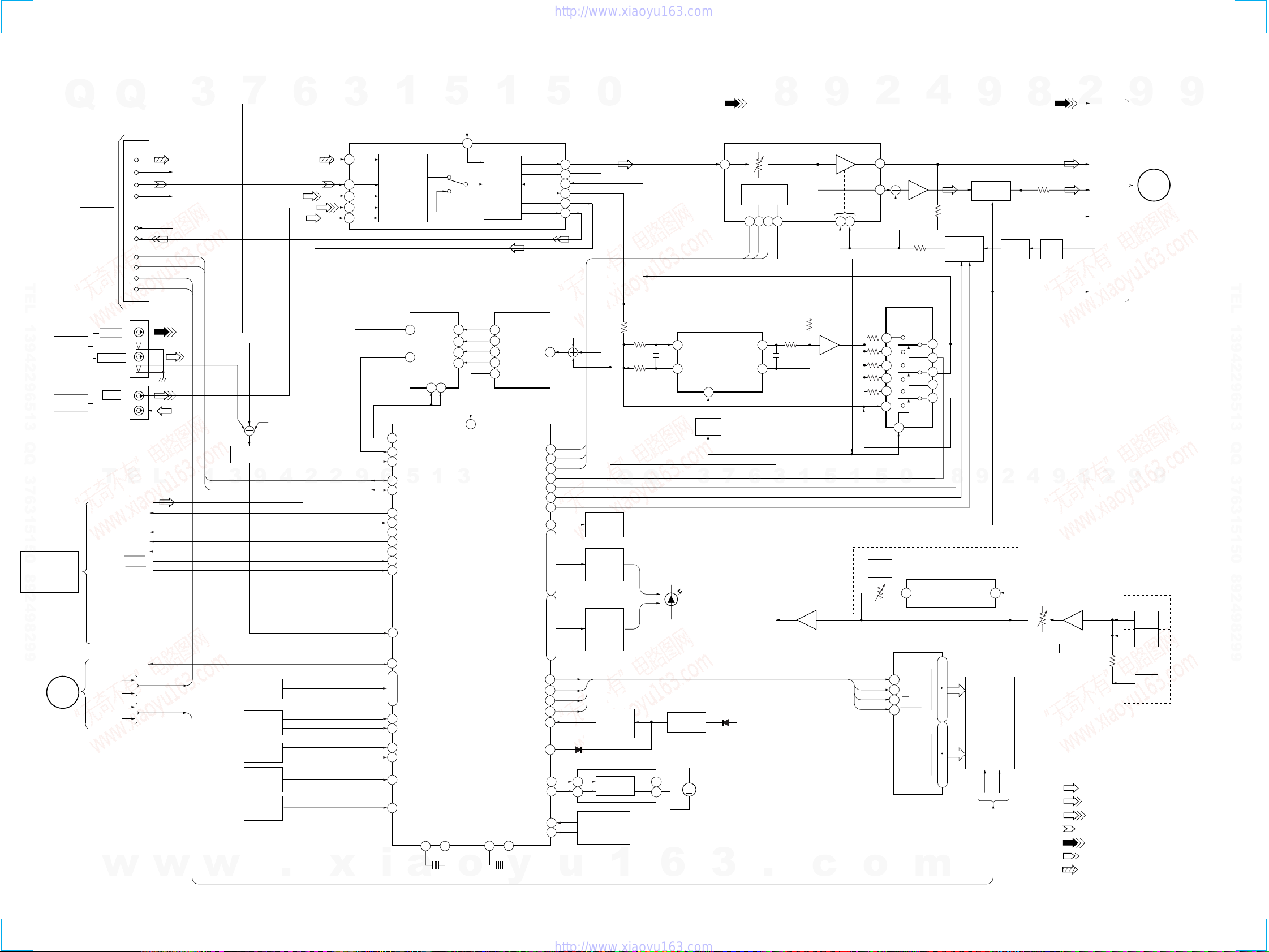
AC IN
UNIT HTC-WX5
SYSTEM CONTROL 17P
w
w
w
.
x
i
a
o
y
u
1
6
3
.
c
o
m
Q
Q
3
7
6
3
1
5
1
5
0
9
9
2
8
9
4
2
9
8
T
E
L
1
3
9
4
2
2
9
6
5
1
3
9
9
2
8
9
4
2
9
8
0
5
1
5
1
3
6
7
3
Q
Q
TEL 13942296513 QQ 376315150 892498299
http://www.xiaoyu163.com

6
LED and Fluorescent IndicatorTube All Lit, Key Check Mode (Do not connect the HTC-WX5.)
Procedure:
1. Press 1/u button to turn the set ON.
2. Press the OPEN/CLOSE button to open the sliding panel.
3. Press three buttons DSP DELAY , ENTER/NEXT , and DISPLAY/DEMO simultaneously.
4. LEDs and fluorescent indicator tube are all turned on. Each time the MOVIE button is pressed, the fluorescent indicator tube lights up
as follows:
lights up completely nlights up partially 1 nlights up partially 2 nlights up completely.
5. Press GAME button, and the key check mode is activated.
6. In the key check mode, the fluorescent indicator tube displays “K @@ J0 V0”. Each time a button is pressed, “K”value decreases.
However, once a button is pressed, it is no longer taken into account. (@@ means the total of buttons)
“J” Value increases like 1, 2, 3 ... if rotating JOG knob in “+” direction, or it decreases like 0, 9, 8 ... if rotating in “-” direction.
“V”Value increases like 1, 2, 3 ... if rotating VOLUME knob in “+” direction, or it decreases like 0, 9, 8 ... if rotating in “-” direction.
7. Pressing all buttons lights up the fluorescent indicator tube completely.
8. To exit from this mode, press three buttons EDIT , ENTER/NEXT and DISPLAY/DEMO simultaneously. (COLD RESET)
9. To exit from this mode, press three buttons in the same manner as step 1, or disconnect the power cord.
CD,TAPE Deck Aging Mode (This mode can be used only when the HTC-WX5 is connected.)
This mode can be used for checking the operations of the CD player and tape deck.
• When problems occur;
Aging stops, and the stopped state is displayed on the fluorescent indicator tube.
• When no problems;
Aging continues.
Preparations:
• Set the CD on the DISC1 tray.
• Insert a commercially available tape for recording (tapes which contents can be erased, etc.) in decksA and B.
Setting the aging mode:
Press the PLAY MODE button, ENTER/NEXT button, and STEREO/MONO button together.
When the aging mode is set, the CD roulette mark blinks. To exit the mode, press the 1/u button and turn OFF the power.
Sequence:
The aging mode is executed in the following sequence.
If the function is set to “CD” when the aging mode is set, aging is performed starting from the CD player. When set to “TAPE A” or “TAPE
B”, aging is started from deck A.
If the function is set to others, aging will not be started until the function is switched to CD or TAPE.
Display of status:
• The aging status is displayed on the fluorescent indicator tube.
• Normally, the CD player displays the remaining aging time. But if operations ended abnormally, it displays the cause.
• During the aging of the tape deck, the operations performed will be displayed. If operations ended abnormally, this will be displayed at the
fluorescent display tube.
CD Player
• During normal operations:
Display of fluorescent indicator tube
**1-@@
**: Displays “CD” and the remaining aging time (minutes) alternately. The remaining aging time is counted down from 12.
@@: Track number being accessed.
Aging of CD player (12 minutes)
Aging of deck A
Aging of deck B 10 minutes
(half)
w
w
w
.
x
i
a
o
y
u
1
6
3
.
c
o
m
Q
Q
3
7
6
3
1
5
1
5
0
9
9
2
8
9
4
2
9
8
T
E
L
1
3
9
4
2
2
9
6
5
1
3
9
9
2
8
9
4
2
9
8
0
5
1
5
1
3
6
7
3
Q
Q
TEL 13942296513 QQ 376315150 892498299
http://www.xiaoyu163.com

7
•When operations end abnormally:
Display of fluorescent display tube
Display of Operations
TAPE A AG-1
TAPE A AG-2
TAPE A AG-3
TAPE A AG-4
TAPE A AG-5
TAPE B AG-1
TAPE B AG-2
TAPE B AG-3
TAPE B AG-4
TAPE B AG-5
Operations during aging
• Operations are performed in the following sequence during aging.
<CD player>
1. The CD tray rotates and disc 1 is selected.
2. Chucking is performed.
3. TOC is read.
4. Track 1 played back for 2 seconds.
5. The last track is played back for 2 seconds.
6. 1 to 5 is repeated.
7. After 12 minutes of aging, aging is switched to the tape deck.
<Tape Deck>
1. The tape in deck A and B are rewound to the head at the same time.
2. The FWD side is played back for 100 seconds.
3. The tape is fast forwarded (FF) for 20 seconds. The following procedure is performed when the tape end is reached before the 20
seconds.
4. The REV side is played back for 100 seconds.
5. The tape is rewound to the head (REW).
6. The FWD side is played back for 100 seconds.
7. The tape is fast forwarded (FF) for 20 seconds. The following procedure is performed when the tape end is reached before the 20
seconds.
8. The REV side is played back for 100 seconds.
9. The tape is rewound to the head (REW).
10. The tape in deck A is rewound to the head.
11. The FWD side is played back for 100 seconds.
12. The tape is fast forwarded (FF) for 20 seconds.
The following procedure is performed when the end is reached before the 20 seconds.
13. Aging is switched to the CD player.
Display
NO DISC ERR
FOCUS1 ERR
FOCUS2 ERR
GFS ERR
FBIAS ERR
SENSOR ERR
TABLE ERR
TRAY ERR
Main Cause
DISC 1 is NO DISC from the beginning
Focus is not imposed properly
The focus deviated several times after the disc rotated normally
GFS ERROR
Error during focus bias adjustment
DISC 1 was found to be NO DISC by the disc sensor
The table did not rotate normally
The tray containing the BD did not operate normally
Tape Deck
Operation
TAPEA, B REW
TAPE A FWD
TAPE A FF
TAPE A REV
TAPE A REW
TAPE B REW
TAPE B FWD
TAPE B FF
TAPE B REV
TAPE B REW
Timing of Ending
Shutoff
100 seconds playback
20 seconds or shutoff
100 seconds playback
Shutoff
Shutoff
100 seconds playback
20 seconds or shutoff
100 seconds playback
Shutoff
w
w
w
.
x
i
a
o
y
u
1
6
3
.
c
o
m
Q
Q
3
7
6
3
1
5
1
5
0
9
9
2
8
9
4
2
9
8
T
E
L
1
3
9
4
2
2
9
6
5
1
3
9
9
2
8
9
4
2
9
8
0
5
1
5
1
3
6
7
3
Q
Q
TEL 13942296513 QQ 376315150 892498299
http://www.xiaoyu163.com

8
PANEL Aging Mode
This mode is used for opening and closing the sliding panel continuously.
Setting the aging mode :
With the set at standby condition, press FLASH button, ENTER/NEXT button and STEREO/MONO button together.
The aging will start and sliding panel will follow aging sequence as described below.
• When problems occur ;
Aging stops and “AGING ERROR” is displayed on the fluorescent indicator tube.
• When no problems;
Aging is carried out repeatedly. After 65000 times, “AGING STOP” is displayed and aging stops.
Aging Sequence
Counts up
n n
Panel open Panel close
n
Stops for one second in the opened state
Stops for one second in the closed state
Each time the DISPLAY/DEMO button is pressed, the display switches as follows.
AGING @@@@@ (No. of agings carried out)
OP MAX @.@@ (Maximum time taken for OPEN:In seconds)
OP MIN @.@@ (Minimum time taken for OPEN:In seconds)
CL MAX @.@@ (Maximum time taken for CLOSE:In seconds)
CL MIN @.@@ (Minimum time taken for CLOSE:In seconds)
w
w
w
.
x
i
a
o
y
u
1
6
3
.
c
o
m
Q
Q
3
7
6
3
1
5
1
5
0
9
9
2
8
9
4
2
9
8
T
E
L
1
3
9
4
2
2
9
6
5
1
3
9
9
2
8
9
4
2
9
8
0
5
1
5
1
3
6
7
3
Q
Q
TEL 13942296513 QQ 376315150 892498299
http://www.xiaoyu163.com

STR-WX5
99
SECTION 4
DIAGRAMS
4-1. CIRCUIT BOARDS LOCATION
DISPLAY Section
•Waveform
5MHz
5.3Vp-p
IC501 0X2
IC501 !£ XT2
1
2
32.768kHz
5Vp-p
THIS NOTE IS COMMON FOR PRINTED WIRING
BOARDS AND SCHEMATIC DIAGRAMS.
(In addition to this,the necessary note is printed
in each block.)
For schematic diagrams.
Note:
• All capacitors are in µF unless otherwise noted. pF: µµF
50 WV or less are not indicated except for electrolytics
and tantalums.
• All resistors are in Ωand 1/4W or less unless otherwise
specified.
•¢: internal component.
•2: nonflammable resistor.
•1: fusible resistor.
•C: panel designation.
For printed wiring boards.
Note:
•X: parts extracted from the component side.
•Y: parts extracted from the conductor side.
•p: parts mounted on the conductor side.
•®:Through hole.
•¢: internal component.
•b: Pattern from the side which enables seeing.
•U: B+ Line.
•V: B– Line.
•H: adjustment for repair.
• Voltages and waveforms are dc with respect to ground
under no-signal (detuned) conditions.
• Voltagesaretakenwith aVOM(Inputimpedance 10MΩ).
Voltage variations may be noted due to normal produc-
tion tolerances.
• Waveforms are taken with a oscilloscope.
Voltage variations may be noted due to normal produc-
tion tolerances.
• Circled numbers refer to waveforms.
• Signal path.
F: FM
f: AM
L: AUDIO (AV INPUT)
g: MD/VIDEO
i:VIDEO (AV INPUT)
E: PB (DECK A)
G: REC (DECK B)
J: CD
• Abbreviation
EA3 : Saudi Arabia model.
EA4 : Israel model.
EA : Middle East model. (Saudi Arabia and Israel)
AUS : Australian model.
SP : Singapore model.
MY : Malaysia model.
TW :Taiwan model.
JE :Tourist model.
AR : Argentine model.
TH :Thai model.
Note: The components identified by mark !or dotted line
with mark !are critical for safety.
Replace only with part number specified.
• Indication of transistor
CThese are omitted
EB
Q
C
These are omitte
d
EB
MIC / ECHO board
POWER AMP board
SURR SPK board
PRIMARY board ENCAPSULATED COMPONEN
T
(EXCEPT JE)
TUNER board (JE)
SECONDARY board
HEADPHONE board
LOADING PANEL board
FRONT AV board
PANEL board MAIN board
MOTOR board
DETECTOR board
w
w
w
.
x
i
a
o
y
u
1
6
3
.
c
o
m
Q
Q
3
7
6
3
1
5
1
5
0
9
9
2
8
9
4
2
9
8
T
E
L
1
3
9
4
2
2
9
6
5
1
3
9
9
2
8
9
4
2
9
8
0
5
1
5
1
3
6
7
3
Q
Q
TEL 13942296513 QQ 376315150 892498299
http://www.xiaoyu163.com

STR-WX5
1010
4-2. BLOCK DIAGRAM
MAIN SECTIOAN
5
3
2
1
SPEANA
SELECTOR
IC505
SPEANA
BPF FILTER
IC506
4
15
22
25
910
26
27
55
56
RESET
LED
ON/OFF
SWITCH
Q531-535,
Q538-540
LED
ON/OFF
SWITCH
Q502-512
SWITCH
Q501
IC891
D504
DATA
CLK
LAT
RST D507
PANEL
LED
+5.6V
RESET
IC502
ECHO
LEVEL
MIX
MIC
MIC 1
J6001
EXCEPT JE
MODEL
JE MODEL
JE MODEL
J6002
MIC 2
MIC LEVEL
MUTE
Q183
SWITCH
Q132 DET
D131
DBFB
SELECTOR
IC112
KEY
MATRIX
MULTI JOG
STATION
S653
VOLUME
S652
SLIDING
SENSOR
IC504,Q513
REMOTE
SENSOR
IC503
MUTE
SWITCH
Q121
35
36
09
41
94
SPEANA CONT
Y
Z
SPEANA0
SPEANA1
I2C DATA
I2C CLK
DATA OUT
DATA IN
LAT
CLK
ST MUTE
STREO
TUNED
AV IN
POWER ON/OFF
KEY0
I
KEY3
JOG A
JOG B
VOL A
VOL B
SENSOR IN
SIRCS IN
GEQ DATA
VA CS
Y1
Y2
Z1
Z2 4
16
17 f1
f2
15 f3
14 f4
13 f
LINE
IN
GEQ CLK
37
38
32
5
6
16
G0
G15
DATA
CLK
CS
RESET
DATA
CLK
LAT
RST
RV6001(2/2)
MIC AMP
IC6001(2/2)
ECHO PROCESSOR
IC6002
FL601
DISPLAY CONTROL
IC601
FLUORESCENT
INDICATOR
TUBE
15
14
13
8
76
LPF 2 OUT LPF 1 IN 1
1
RV6001(1/2)
MIC AMP
IC6001(1/2)
3
2
10
MASTER CONTROL
IC501
92
90
89
93
B
POWER
SECTION
COM DIN
ST L
COM DATA
ST CE
COM CLK
MUTE
STEREO
TUNED
POWER ON/OFF
FM/AM TUNER
TUNER UNIT IS
SUPPLIED AS
THE ASSEMBLED
BLOCK
(Page 11)
(Page 11)
• R CH: Same as L ch
• SIGNAL PATH
: FM
: AUDIO(AV INPUT)
: MD/VIDEO
: PB
: VIDEO(AV INPUT)
: REC
: CD
• Abbreviation
EA3 : Saudi Arabia model.
20
C
POWER
SECTION
43
10 11
21
18
19
42
86
87
88
R-CH
R-CH
AV SWITCH
Q6301 96
97
GEQ LAT 95
LEVEL B 3
LEVEL A 2
2
1
3
DBFB B2 5
DBFB B1 6
42 41
33
123
9
8
13
CLOCK
DELAY
IC401
AMP
IC113(1/2)
SELECTOR
IC402
32 34 30
3
5
9
15
10
11
VIDEO
L-CH
S/W
MUTE
L+R
TA MUTE
38
36
VOLUME
IC111(2/2)
40
AMP
IC113(2/2)
39
60
4
3
57
58
TA MUTE
LED
LED
FL DATA
FL CLK
FL LAT
RESET
FL RESET
ACCUT
MOTOR 1
MOTOR 2
PANEL OPEN
PANEL CLOSE
X2 X1
X501
5MHz X502
32kHz
XT2 XT1
7
63
I
67
70
72
73
50
I
54
57
I
62
.
.
.
.
82
83
84
85
13 14
MM891
PANEL
MOTOR
PANEL
OPEN/CLOSE
S892
MOTOR
DRIVER
VF1
VF2
AC1
AC2
28
I
31
2
1
CN101
J6301
J101
TO
HTC-WX5
VIDEO
AUDIO L
AV INPUT
(VIDEO 2)
7
9
5R-CH(REC R)
R-CH(CD R)
R-CH(PB R)
IIC DATA
IIC CLK
AC1
AC2
6
17
13
14
16
69
65
68
SELECT
SWITCH EQ
AMP
CD
V2
MD/V1
TC
TU
2
66
67 MICON
INTERFACE
131
57
1
2
14
4
12
13
2
LPF 1 IN
LPF 1 OUT
LPF 2 IN
LPF 2 OUT
12
I
1
64
I
61
59
I
33
31
I
23
S0
S35
JE : Tourist model.
SYSTEM
CONTROL
MD/
VIDEO 1
IN L
OUT L
15
EQ
IC111(1/2)
BUFFER
Q401
R-CH
R-CH
w
w
w
.
x
i
a
o
y
u
1
6
3
.
c
o
m
Q
Q
3
7
6
3
1
5
1
5
0
9
9
2
8
9
4
2
9
8
T
E
L
1
3
9
4
2
2
9
6
5
1
3
9
9
2
8
9
4
2
9
8
0
5
1
5
1
3
6
7
3
Q
Q
TEL 13942296513 QQ 376315150 892498299
http://www.xiaoyu163.com

STR-WX5
1111
POWER SECTION
• R CH : Same as L ch
• SIGNAL PATH
: FM
:VIDEO (AV INPUT)
• Abbreviation
EA3
SP
MY
JE
TW
AR
: Saudi Arabia model.
: Singapore model.
: Malaysia model.
:Tourist model.
:Taiwan model.
:Argertine model.
R-CH
R-CH
R-CH
R-CH
D751
D761
RY751
RY781
OVER LOAD
DET
Q952
OVER LOAD
SWITCH
Q851
POWER AMP
IC901
PROTECTOR
IC851
L-CH
L+R
S/W
VIDEO
TA MUTE
MUTE
POWER ON/OFF
E,EA3,SP,MY,AR,TW,JE
AC
IN
PHONES
J755
R-CH
MONITOR
OUT
J781
SUPER
WOOFER
FRONT
SPEAKER
TB751
REAR
SPEAKER
TB201
M
M901
FAN
ST+10V
UNREG
+12V
+7V
+5.6V
+5V D813
D821
-7V
+B
-B
VG
Rch
MOTOR
MUTE
SWITCH
Q901
MUTE
Q181
SWITCH
Q853
D852,853
PROTECTOR VCC ON
MUTE ST+10V
REG
IC804
VOLTAGE
SELECTOR
S871
VF1
VF2
AC1
AC2
T901
POWER
TRANSFORMER
MAIN
SECTION
B
09
(Page 17)
8
1
4
3 1
L
6
7
2
20 15
RECT
D810,811
+7V REG
IC801
+5.6V REG
IC803
FAN MOTOR
REG
Q731,732
POWER ON
MUTE
Q852
RECT
D805-808
RECT
D801
RECT
D802, 803
VG REG
Q801
31
31
32
-7V REG
IC802
VF1
VF2
AC1
AC2
R
+
–
+
–
MAIN
SECTION
C
(Page 17)
Q854
Q855
w
w
w
.
x
i
a
o
y
u
1
6
3
.
c
o
m
Q
Q
3
7
6
3
1
5
1
5
0
9
9
2
8
9
4
2
9
8
T
E
L
1
3
9
4
2
2
9
6
5
1
3
9
9
2
8
9
4
2
9
8
0
5
1
5
1
3
6
7
3
Q
Q
TEL 13942296513 QQ 376315150 892498299
http://www.xiaoyu163.com

STR-WX5
1212
4-3. PRINTED WIRING BOARD MAIN SECTION • Refer to page 9 for Circuit Boards Location.
(Page 19)
(Page 22)
(Page 21) (Page 17)(Page 21)
(Page 17)
(Page 15)
(Page 15)
(Page 17)
12
14
16
BB
JW264
Ref. No. Location
• Semiconductor
Location
D101 B-11
D102 B-11
D131 E-9
D401 D-5
D402 D-5
D403 C-9
D751 F-11
D752 F-12
D761 E-12
D781 G-10
D801 E-4
D802 F-5
D803 E-4
D804 C-2
D805 F-4
D806 F-4
D807 F-4
D808 F-4
D810 E-4
D811 E-4
D812 C-2
D813 B-2
D851 G-8
D852 G-8
D853 G-8
IC111 C-10
IC112 E-10
IC113 E-9
IC401 E-7
IC402 D-6
IC801 B-2
IC802 C-3
IC803 B-2
IC804 D-4
IC851 G-9
Q121 B-2
Q132 D-10
Q182 E-11
Q183 E-8
Q401 D-7
Q731 G-11
Q732 G-10
Q801 C-2
Q851 G-9
Q852 H-8
Q853 H-8
Q854 H-7
Q855 H-6
w
w
w
.
x
i
a
o
y
u
1
6
3
.
c
o
m
Q
Q
3
7
6
3
1
5
1
5
0
9
9
2
8
9
4
2
9
8
T
E
L
1
3
9
4
2
2
9
6
5
1
3
9
9
2
8
9
4
2
9
8
0
5
1
5
1
3
6
7
3
Q
Q
TEL 13942296513 QQ 376315150 892498299
http://www.xiaoyu163.com

STR-WX5
1313
4-4. SCHEMATIC DIAGRAM MAIN(1/2) SECTION • Refer to page 24 for IC Block Diagrams.
(Page 15)
(Page 14) (Page 14) (Page 14) (Page 14)
(Page 18)
16
w
w
w
.
x
i
a
o
y
u
1
6
3
.
c
o
m
Q
Q
3
7
6
3
1
5
1
5
0
9
9
2
8
9
4
2
9
8
T
E
L
1
3
9
4
2
2
9
6
5
1
3
9
9
2
8
9
4
2
9
8
0
5
1
5
1
3
6
7
3
Q
Q
TEL 13942296513 QQ 376315150 892498299
http://www.xiaoyu163.com

STR-WX5
1414
4-5. SCHEMATIC DIARGAM MAIN(2/2) SECTION • Refer to page 12 for Printed Wiring Board. • Refer to page 24 for IC Block Diagrams.
The components identified by mark !or dotted
line with mark !are critical for safety.
Replace only with part number specified.
(Page 20)
(Page 23) (Page 15) (Page 20) (Page 16)
(Page 16)
(Page 16)
(Page 13)(Page 13)(Page 13)(Page 13)
16
0.8
0.1
Q854
BN1F4M
Q855
2SC2958L
RELAY SWITCH
R857
22k
0
w
w
w
.
x
i
a
o
y
u
1
6
3
.
c
o
m
Q
Q
3
7
6
3
1
5
1
5
0
9
9
2
8
9
4
2
9
8
T
E
L
1
3
9
4
2
2
9
6
5
1
3
9
9
2
8
9
4
2
9
8
0
5
1
5
1
3
6
7
3
Q
Q
TEL 13942296513 QQ 376315150 892498299
http://www.xiaoyu163.com

STR-WX5
1515
4-6. SCHEMATIC DIAGRAM AV/MIC SECTION 4-7. PRINTED WIRING BOARD AV/MIC SECTION
• Refer to page 24 for IC Block Diagrams. • Refer to page 9 for Circuit Boards Location.
(Page 14)
(Page 18)
(Page 13)
(Page 16)
16
MODEL
MODEL
MODEL
MODEL
(Page 12)
(Page 12)
(Page 19)
(Page 17)
16
16
4
MODEL
MODEL
MODEL
MODEL
4
w
w
w
.
x
i
a
o
y
u
1
6
3
.
c
o
m
Q
Q
3
7
6
3
1
5
1
5
0
9
9
2
8
9
4
2
9
8
T
E
L
1
3
9
4
2
2
9
6
5
1
3
9
9
2
8
9
4
2
9
8
0
5
1
5
1
3
6
7
3
Q
Q
TEL 13942296513 QQ 376315150 892498299
http://www.xiaoyu163.com

STR-WX5
1616
4-8. SCHEMATIC DIAGRAM POWER AMP SECTION
The components identified by mark !or dotted
line with mark !are critical for safety.
Replace only with part number specified.
(Page 14)
(Page 14)
(Page 14)
(Page 15)
16
1/4W
1/4W
1/4W
w
w
w
.
x
i
a
o
y
u
1
6
3
.
c
o
m
Q
Q
3
7
6
3
1
5
1
5
0
9
9
2
8
9
4
2
9
8
T
E
L
1
3
9
4
2
2
9
6
5
1
3
9
9
2
8
9
4
2
9
8
0
5
1
5
1
3
6
7
3
Q
Q
TEL 13942296513 QQ 376315150 892498299
http://www.xiaoyu163.com

STR-WX5
1717
4-9. PRINTED WIRING BOARD POWER AMP SECTION • Refer to page 9 for Circuit Boards Location.
(Page 12)
(Page 12)
(Page 15)
(Page 12)
16
3
3
16
w
w
w
.
x
i
a
o
y
u
1
6
3
.
c
o
m
Q
Q
3
7
6
3
1
5
1
5
0
9
9
2
8
9
4
2
9
8
T
E
L
1
3
9
4
2
2
9
6
5
1
3
9
9
2
8
9
4
2
9
8
0
5
1
5
1
3
6
7
3
Q
Q
TEL 13942296513 QQ 376315150 892498299
http://www.xiaoyu163.com

STR-WX5
1818
4-10. SCHEMATIC DIAGRAM DISPLAY SECTION • Refer to page 25 for IC Block Diagrams. • Refer to page 26 for IC Pin Function.
(Page 20)
(Page 13) (Page 20)
(Page 15)
16
3.6
3.5
3.5
w
w
w
.
x
i
a
o
y
u
1
6
3
.
c
o
m
Q
Q
3
7
6
3
1
5
1
5
0
9
9
2
8
9
4
2
9
8
T
E
L
1
3
9
4
2
2
9
6
5
1
3
9
9
2
8
9
4
2
9
8
0
5
1
5
1
3
6
7
3
Q
Q
TEL 13942296513 QQ 376315150 892498299
http://www.xiaoyu163.com

STR-WX5
1919
4-11. PRINTED WIRING BOARD DISPLAY SECTION • Refer to page 9 for Circuit Boards Location.
Ref. No. Location
D501 E-2
D502 D-3
D504 E-4
D505 F-4
D506 F-3
D507 F-3
D509 F-6
D511 D-1
D512 D-8
D513 D-7
D514 D-7
D515 D-7
D516 D-6
D517 D-6
D518 D-5
D519 D-5
D520 D-4
D521 D-5
D522 D-3
IC501 B-4
IC502 E-2
IC503 B-10
IC505 D-10
IC506 C-10
IC601 B-7
Q501 D-3
Q502 D-8
Q503 D-7
Q505 D-7
Q504 D-7
Q506 D-6
Q507 D-6
Q508 D-5
Q509 D-5
Q510 D-5
Q511 D-4
Q512 E-3
Q513 B-9
• Semiconductor
Location
(Page 12)
(Page 21)
(Page 15)
(Page 21)
16
3
EA4,TH,JE MODEL
EXCEPT EA4,TH,JE MODEL
E,AR MODEL
EXCEPT E,AR MODEL
EXCEPT AUS MODEL
EXCEPT E,AR,JE MODEL
E,AR,JE MODEL AUS MODEL
CN505
w
w
w
.
x
i
a
o
y
u
1
6
3
.
c
o
m
Q
Q
3
7
6
3
1
5
1
5
0
9
9
2
8
9
4
2
9
8
T
E
L
1
3
9
4
2
2
9
6
5
1
3
9
9
2
8
9
4
2
9
8
0
5
1
5
1
3
6
7
3
Q
Q
TEL 13942296513 QQ 376315150 892498299
http://www.xiaoyu163.com

STR-WX5
2020
4-12. SCHEMATIC DIAGRAM SLIDING PANEL SECTION • Refer to page 28 for IC Block Diagrams.
(Page 18)
(Page 14)
(Page 18)
(Page 14)
0.6
12.7
12.7
0.6
0.7
4.5
0
0
0
3.6
3.5
16
3.5
3.5
4.9
4.9
4.9
w
w
w
.
x
i
a
o
y
u
1
6
3
.
c
o
m
Q
Q
3
7
6
3
1
5
1
5
0
9
9
2
8
9
4
2
9
8
T
E
L
1
3
9
4
2
2
9
6
5
1
3
9
9
2
8
9
4
2
9
8
0
5
1
5
1
3
6
7
3
Q
Q
TEL 13942296513 QQ 376315150 892498299
http://www.xiaoyu163.com
Other manuals for STR-WX5
2
Table of contents
Other Sony Receiver manuals

Sony
Sony STR-DH520 User manual

Sony
Sony STR-DH740 User manual

Sony
Sony DWR-S02DN User manual

Sony
Sony STR-DH800 User manual

Sony
Sony STR-DE995 - Fm Stereo/fm-am Receiver User manual

Sony
Sony ICF-2001 User manual

Sony
Sony HCD-DZ110 User manual

Sony
Sony STR-DG710 User manual

Sony
Sony FA-WRR1 User manual

Sony
Sony STR-DA1200ES User manual

Sony
Sony AC-300MD User manual

Sony
Sony STR-DG900 User manual

Sony
Sony STR-DH810 - Audio Video Receiver User manual

Sony
Sony AC-PW20 User manual

Sony
Sony HCD-M80 User manual

Sony
Sony AVD-LS10 User manual

Sony
Sony STR-DG810 User manual

Sony
Sony XAV-V750BT User manual

Sony
Sony ICF-SW55 User manual

Sony
Sony STR-KS2300 - Blu-ray Dvd Receiver Component User manual