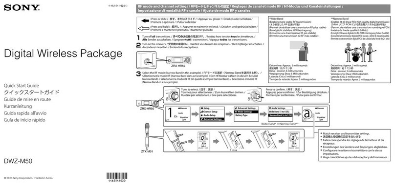
RECEIVER DISPLAY
PORTABLE DIVERSITY TUNER (URX-P03)
1
2
3
4
5
6
10
11
12
13
PHONES (monitor) connector - Connect to headphones to monitor the
audio output.
UWP-D11
CHASSIS & DISPLAY OVERVIEW - RECEIVER
7
8
9
Antenna
Power Indicator - Displays the battery level
RF (radio frequency input) Indicator - Displays the RF input
level as follows:
Infrared Transmitter Port - Sends the set frequency and compander
mode to the transmitter
USB Connector - You can power the unit using a USB cable (either
portable power supply or connected to the mains.
Output Connector - Connect the XLR to stereo mini jack cable here
and the other end to the audio mixer. If using a camera, connect the
stereo mini jack to stereo mini jack cable here and the other end to
the mic input on a camera.
Battery Compartment
+ or - Button - Use these to operate the menu
Display Section
SET Button - Use this to set values/functions in the menu
Power Button - Turns the power on/off
Auxiliary Connector - Used to connect external accessories
Indicator Display Status
ON (Green) Sufcient battery level
Flashing (Green) Battery is getting low
Off Power is off or battery is empty
Indicator Display Status
ON (Green) Input level is 25dBμ or more
ON (Red) Input level is 15 to 25dBμ
Off Input level is 15 dBμ or lower
0 dBμ= 1 μV EMF
A
B
D
E
C
RF Level (reception level) Indicator - Indicates the current recep-
tion level
Battery Level Indicator - Displays the battery level.
Menu Display Section - Displays various functions. Press the + and -
buttons to switch functions.
Peak Indicator - Lights up when the audio signal is 3dB below the lev-
el at which distortion begins as a warning of excessive input level.
Audio Input Level Meter - Displays the audio input level.

