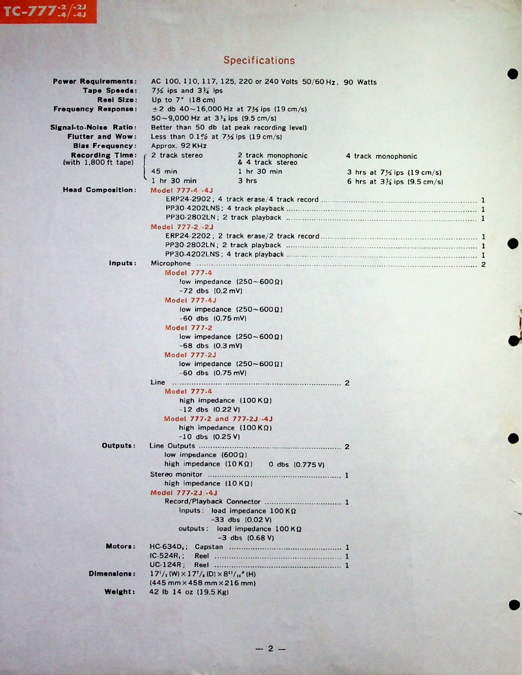
Specifications
4
track
monophonic
Head
Composition:
Inputs
:
2
Outputs
:
2
0
dbs
(0.77
V)
1
1
outputs
:
Motors
:
Dimensions
:
Weight:
2
-
1
1
1
Signal-to-Nolse
Ratio:
Flutter
and
Wow:
Blas
Frequency:
Recording
Time:
(with
1,800
ft
tape)
Power
Requirements:
Tape
Speeds:
Reel
Size:
Frequency
Response:
2
track
monophonic
&
4
track
stereo
1
hr
30
min
3
hrs
3
hrs
at
7'/i
ips
(19
cm/s)
6
hrs
at
3J4ips
(9.
cm/s)
1
1
1
1
1
1
2
IC- 24R,
;
UC-124R;
17*/,
(W)
x
177.
(0)
x
8'7..'
(H)
(44
mm
x
4 8
mm
x
216
mm)
42
lb
14
oz
(19.
Kg)
AC
100,
110,
117,
12 ,
220
or
240
Volts
0/60
Hz,
90
Watts
7%
ips
and
3?4
ips
Up
to
7*
(18
cm)
±2
db
40-16,000
Hz
at
7%
ips
(19
cm/s)
0-9,000
Hz
at
3?;
ips
(9.
cm/s)
Better
than
0
db
(at
peak
recording
level)
Less
than
0.1%
at
7>4ips
(19
cm/s)
Approx.
92
KHz
2
track
stereo
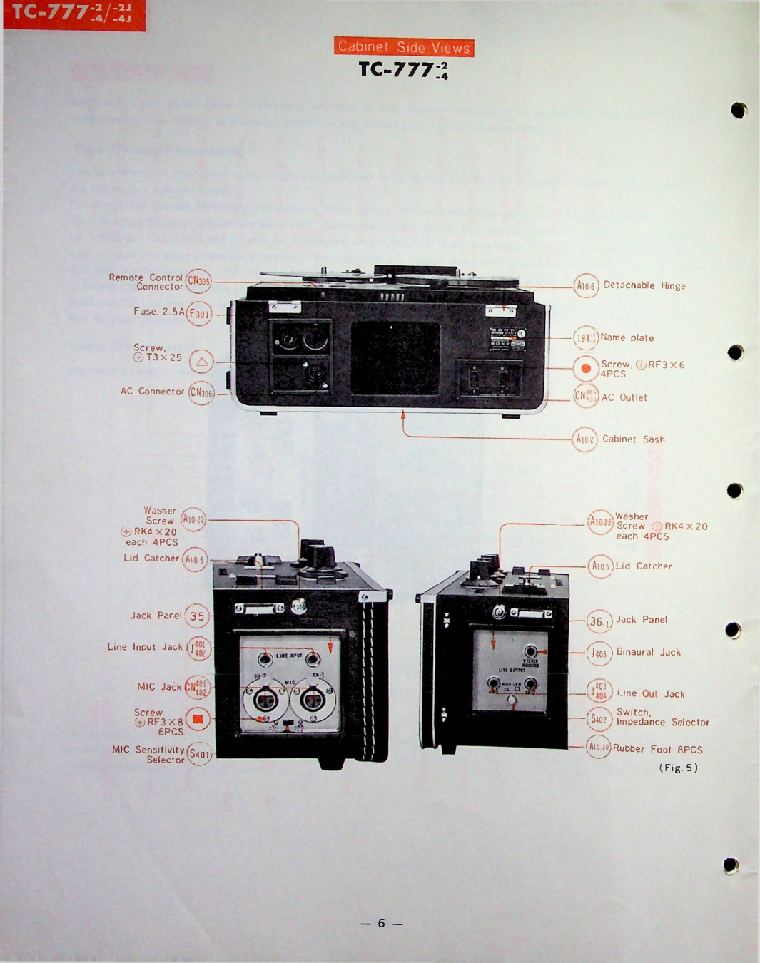
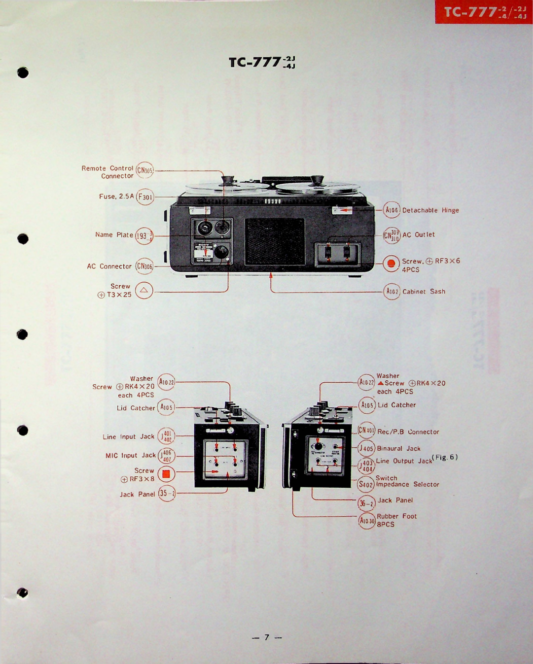
tc
-777:V:4
j
j
Line
...........................................................
Model
777-4
high
impedance
(100
KQ)
-12
dbs
(0.22
V)
Model
777-2
and
777-2J
-4J
high
impedance
(100
KQ)
-10
dbs
(0.2
V)
Line
Outputs
.....................................
low
impedance
(600
Q)
high
impedance
(10
KQ)
Stereo
monitor
...............................
high
impedance
(10
KQ)
Model
777-2J
-4J
Record/Playback
Connector
inputs:
load
impedance
100
KQ
-33
dbs
(0.02
V)
load
impedance
100
KQ
-3
dbs
(0.68
V)
HC-634D,
;
Capstan
..........................................
Reel
....................................................
Reel
....................................................
4
min
k
1
hr
30
min
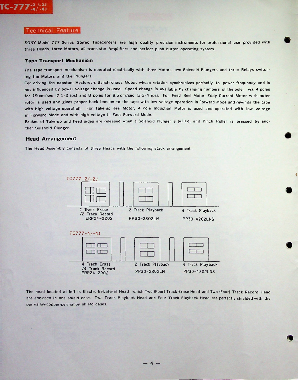
Model
777-4
-4J
ERP24
2902;
4
track
erase/4
track
record
PP30-4202LNS
;
4
track
playback
...................
PP30-2802LN
;
2
track
playback
...................
Model
777-2
-2J
ERP24-2202
;
2
track
erase/2
track
record
PP30-2802LN
;
2
track
playback
...................
PP30
4202LNS
;
4
track
playback
...................
Microphone
..........................................................................
Model
777-4
low
impedance
(2 0
—
600Q)
-72
dbs
(0.2
mV)
Model
777-4J
low
impedance
(2 0
—
600Q)
-60
dbs
(0.7
mV)
Model
777-2
low
impedance
(2 0
—
600Q)
-68
dbs
(0.3
mV)
Model
777-2J
low
impedance
(2 0
—
600Q)
-60
dbs
(0.7
mV)

 User manual")