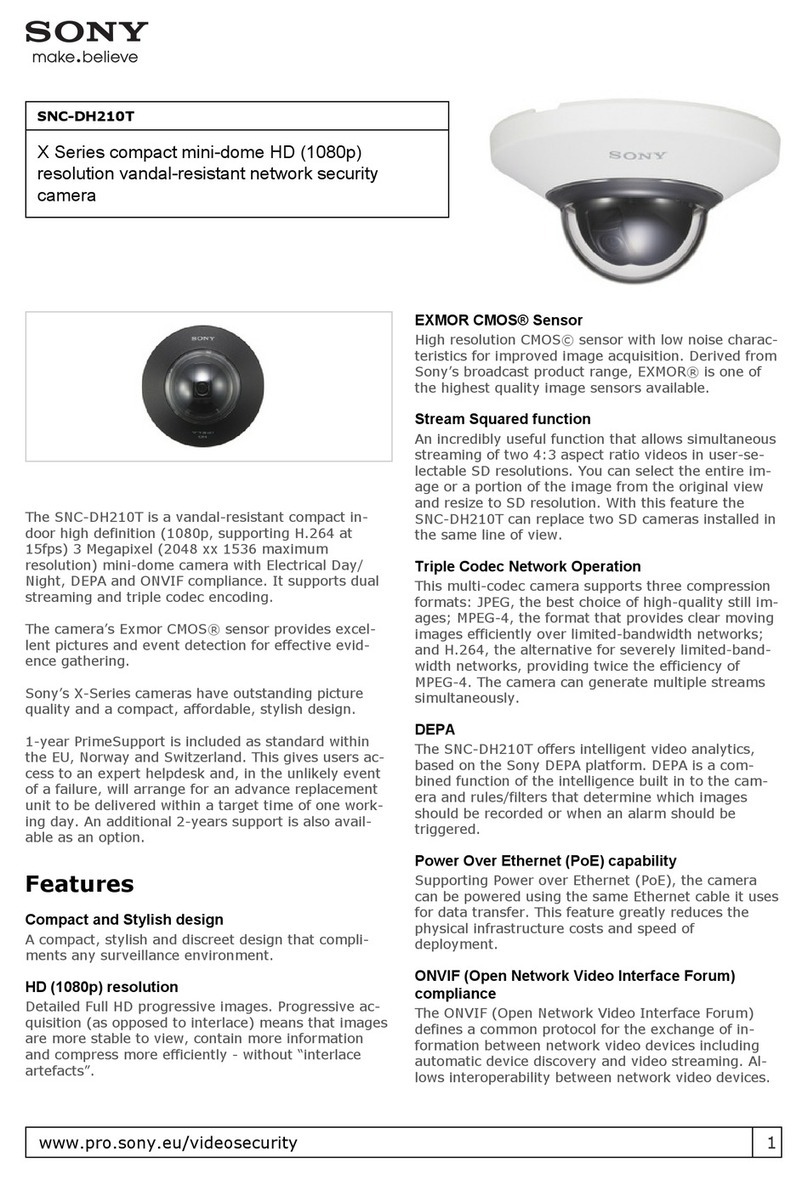
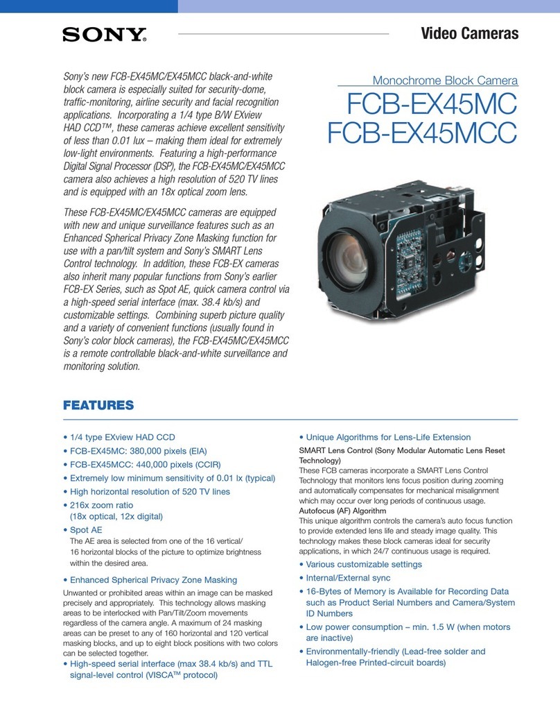
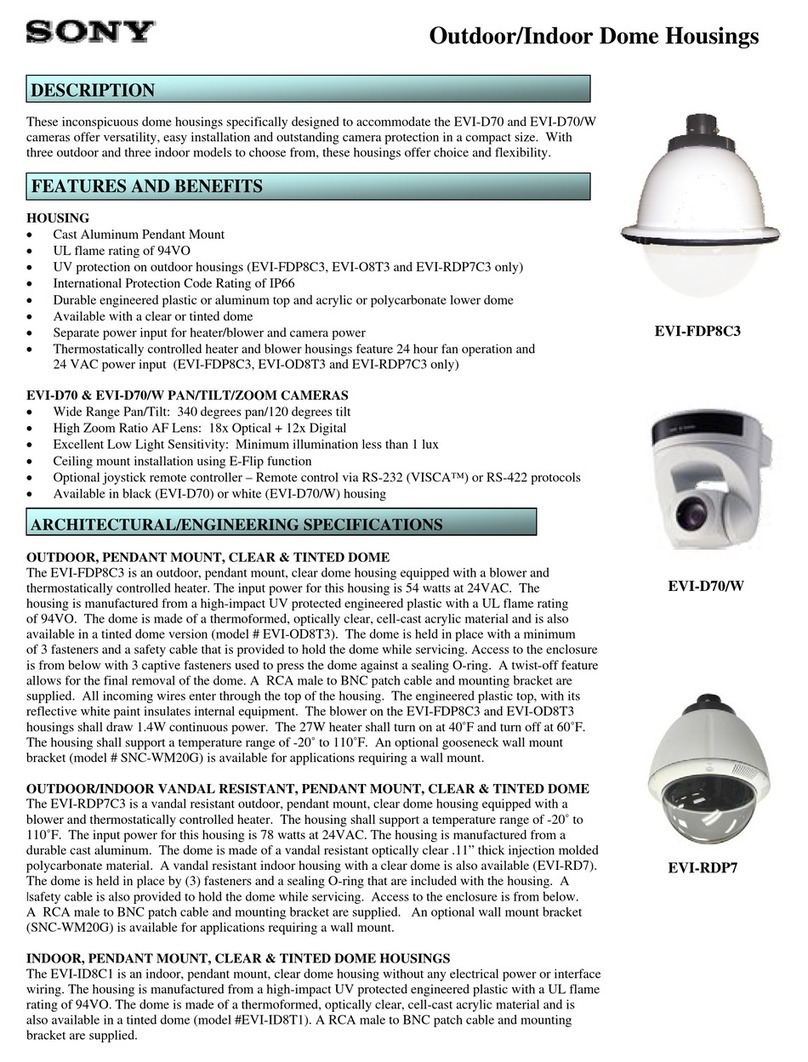
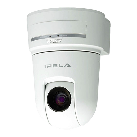
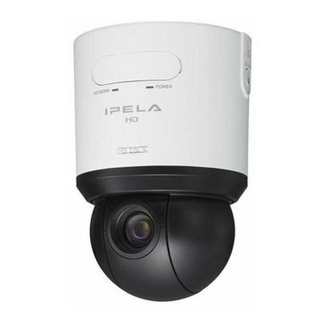
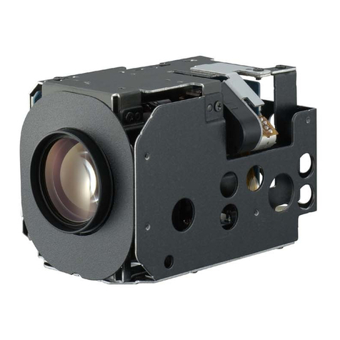
Sony ASL 609 User manual

#
.
i
I
d
,=d
,
j
.$
I
I
PTZDOME CAMERA
OPERATIONMANUAL
Pleaseread
this rnanualthoroughlyprior to installationandoperation


Precautions
l. Please read this manual thoroughly prior to installation and operation. Store this manual
properly for future reference. Consult your speed dome camera dealer if you have
uncertainties or questions.
2. Make sure to use correct power supply indicated in the specifications. Wrong power supply
may cause improper performance, damage of the product, or fire. It is recommended that you
usethe power supply that your speeddome dealer may provide.
3. The High-SpeedDome Cameracontainsprecisionoptical andelectrical instruments.To avoid
possible damage caused by striking or shocking, please handle the unit carefully during
delivery, storage and installation.
4. In the caseof any unusual performance, unplug the unit and contact your dealer immediately
for help. Do not disassembleor remove any internal parts of the unit without professional help.
5. To enswe optimal performance, make sure there is enough distance between video cable and
RM85 wires from theunit andany local high-voltage equipmentor cables.
6. Please do not install and use the unit in an environment with temperature or humidity that
o<ceedstheresfictive limits listed in the specifications.
7. To avoid damageto camera's CCD, do not aim the camera at the sunor very bright object and
do not aim at bright object for a long time evenwhen power is off.
8. Do not use any strong chemical liquids when cleaning. If necessary,useneutral detergent and
water to clean the housing and lower bubble, and gently dry them offwith soft cotton fabric.
9. Always install the unit in a place with enough holding force to avoid dropping the unit. The
required minimum holding force is five times of the total weight of the unit and the support.
10. Always usespecialoptical lenspaperor fabric to cleanlens.
I I' Wear cotton gloves when handling dome bubble during installation or disassernbleto avoid
bubble surface being scratched.
1.Product
Introduction
ThePTZ dome
camera
systemis CCTV front-end
equipmentwith high pricevalue.The
product
hasthefollowing mainfeatures.
. Supporb multiple
protocols.
. Supporb 26x
opticalzoom,l0x digihl zoom,
day/nightwithremovablelR
cut-filter, motion{etecting Sony CCDcamera
. Auto focus and auto iris lens
. OSDmenu
. 0 - 355"
panrotation, 0- 90"tilt range
. 12"/sec
pan
speed,12"/sec
tilt speed.
. Powersource: AC24V
. Gommunicationuses RS485dataport
. lDaddress upto 54
. lP66standardfor all weather proof environmental protection
. 9'ABS outdoor
housing
with heater/blower.
1.1 Specifications
of DomeDrive andHousing
Model ASL309 ASL609
Product
Name OutdoorPTZ
DomeCamera lndoorPTZDomecamera
Built-in
Menu OSDin English
Manual
Languages English
Damera
Supports CNB
Pan
movement 0o
- 355ocontinuous
nft movement 0"
--90"
Pan
speed 12"/sEc
Iilt speed 12"/SEC
lommunication RS485interface
Daddrcss 1- 64addresses
trotocols PelcoD
3audrate 2400
towersupply AC24V/500mA
(no Heater)
{eaterlblower
tower AC24Vt3A
P RATING lP66 Not rated
)perating Temp €0"C (-22"F
)to +60"
C(140"F) 0"C
(32"F)
to +40"C
(104"F)
)imensions D:222mm(9")
H:350mm
(14") D:222mm(9"1;
H:280mm(ll")
,Veight 3.1ks
(6.8lb) 2.ekg
(6.alb)

|-2 CameraSpecifications
SPECIFICATIONS
OFCAiIERAMODULES*
Sub-ilodel c26toDN
lmage
Sensor 7r" Sony Super HAI) GGD
TotalPirels 81{(H}x508(v)
HorizontalRes. llorc than 480TVL
ilin. lllum. (color) 1.0lux
ilin lllum {b/w) 0.0lur (lRON)
Lens F=i.6
-3.78
(ts3.Smmto
91mm
26r Optical.10xdiqital)
Resolution .l80TVL
S/N Ratio >48
dB
Electroshutter auto/manual
1/51F1/10,000s
FocusGontrol auto/manual
lris Control auto/manual
osD English
Day/Night Yes,wilfr removablelR
cut filter
Motion detection Yes(need
to set up in camera
menu)
Scanllode 2:1interlacedscan
Sync. lntemal/extemal (line lock):
auto detect
Power
consumption Mar.4.2W
Dimensions
{mml 50.5161.fu92.3mm
Weiqht Approx 340q
* Detail
dataareavailableupon request

2. Installation
2.I Accessories
Checking
Prior to installation. please make sure all accessories are available. Contact your producl
dealer immediately if any accessoriesare missing or damaged.
Item 309 609
IScrew for cameramountinq I (if camera is not included; suitable for most
commonly used zoom cameras)
2Cotton Gloves I pair
JUser'smanualfor camera I (if cameraisprovided)
4User's manualfor pan/tilt
For theconvenience
of RMA service.
please
storeall original packing materials
properly.
2.2
Dipswitch
Setup
Before installation, correctly setup dome address.
protocol, andbaud rate. Dome address,
protocol and baud rate can be set up through adjusting dipswitches on the dome drive.
2.2.1-
Dome
Address
Setup
Dipswitches I to 6 are for dome address setting. Dome addresscan be set to any number
from 0 to 64. Refer to the following chart in Appendix I for corresponding addressand dipswitch
positions.
Default is l.
2-2.2.
ProtocolandBaudRateSetup
Dipswitches 7 to l0 are for protocol setting; I I and 12are for baud rate. Refer to the
following two tables
for thepositioning of dipswitchesandthe corresponding
protocolsandbaud
rate. Default protocol andbaudratearePelcoD. 2400.Becausethe camera
provided supports
Pelco D (2400) protocol only, pleasekeep the default setting for the protocol and baud rate.
Dipswitch
Positions Baudrate Dipswitch
Positions Baudrate
H1200 H4800
E2400 E9600

NO. Communication
Protocol Communication
Protocol
RecommendedBaud
Rate
78910
IPELCO-D 2400
2.3Wire Connections
Connectowo24VAC power wires (labeledbrown) to your power supply andRS485+ (Red)
andRM85{Black) wires to your control device.Connectcoaxial cableto video oulput. If usinga
bracket, wire connection can be carried out after mounting the unit to the bracket.
Notc: Make sure that the power supply is 24VAC. Pay special attention to correct
connection of power supply wires. Incorrect connection will rcsult in permanent damege of
the unit and may ceusefirc, Any damage causedby imprcper wirc connection is not under
the manufacturrr's warranQr coverage.
2.4InstallationProcedures
2.4.1 CameraMount
Prior to mount a zoom camera to the uniq pleasebe surethat the camera has to support
l.24VAC power input.
2. RS485 control with PelcoD protocol.
Mount the camera to PTZ's camera bracket and make sure that the camera towards the
arrow direction shown on the sticker on the bracket. The camera shall be mounted roughly in the
middle of the bracket. Use the screw provided to tight the camera-Then connect the RS485+ (red)
and RS485- (black), 24VAC power supply wires (two brown wires) and video cable to
corresponding terminals on the back of camera-
2.4
.2 Camera
Configuration
After mount the camer4 camera parameters may need to be configwed correct$ for
proper system performance. To configure the camer4 refer to the camera manual provided for
precise description of the procedures. The following stepsarerecommended.
l. Make surethat the power supply,aswell asall video and control wires, are connected
correctly.Lens cover must beremoved.
2. Connect the unit's RS485 to the control device (keyboard or a DVR). and connect the
video to amonitor.
3. Turn power on.Video imageshallnow appearon thescreenof themonitor.
Note: If no image shows, turn ofr thc unit immediately and check wire connections.
4. Pushthe menu button at the back of the camerato enter camera OSD menu.
5. Follow camera's
manualto changecamera
parameters.
The following pararneters
must

be configured correctly in order to control the camerawith your control device.
. CameralD (default l)
. Protocol (defaultP/D. i.e.,PelcoD)
. Auto focus mode (defaultAUTO)
Depending on the contnol device and the application, other camera parameters (e.g.,
motion detection mode) may also need to be configured. Refer to the manual of yow control
device aswell asthe manual for your camera for details.
6. Try to control the camera through the control device. Repeat step4 if necessary.
2.4.3Mount/Dismount
LowerDome
Beforemounting
thelowerdome,makesurethat
' CameraID, protocol,
andbaudrate
arecorrectly
setupwith dipswitches.
. Camera
lens
coverisremoved.
. Cameraisconfigured
properly.
To keepfingerprintsandscratchesfrom distortingthe lower dome,wearthe provided
gloves
whenhandling
thelowerdome.Tomountthelowerdome,carefullylinethescrew
holeson
theback
boxupwith thescrewsonthelowerdomering andtightenthescrews
(referto thefigure
below).
Do notremove
theplastic
wraponthelowerdome
until all stepsaredone.
Dothereverse
for dismounting.
2.4.4
Mount
toaSupport
Send
wiresthrough
thesupport
andtightenthemountingscrewson thesupport,or follow
the manualof the support.If using a supportprovidedby us, refer to the following chart for
supportmounting.
2.4.5 Install ttre Entire Unit
Notc: Since thc horizontel rotation range of the YIZ umit is not 360", please identify and
avoid the blind angle position before insbll tfre unit. For outdoor model, the blind
angle is at the support (bracket) position. For indoor model, the blind angle position is
shown on the stickeron the upper dome housing.
Always install the unit in a place with enough holding force to support the weight of the
unit The required minimum holding force is five times the total weight of the unit and the support.
Due to the fact that installation of an entire unit is subject to local administrative regulations, we
*:lnrlit

can not provide more detailed instructions. Make sure to follow all relevant larrs and goverffnent
regulations when installing the unit. Refer to the following chars for installation dimensions (units
arein millimeters).
br:lr:tr:t ar.*r::aj*g {:rte
CeilingInstall
BracketInstall
r-fer tu right
CeilingRecessInstall

3.Operation
The PTZ camera system can be controlled via keyboard, matrix, or DVR (digital video
recorder). In order to operale thePTZ unit, control device and PTZ must have sameprotocol and
baud rate. For most of control devices. PTZcutbe controlled asfollowing.
l. To move PTZ vertically or horizontally, use
joystick, arrow keys, or mouse to click arrow
buttons.
Notc: Since the horizontal rotation range of the WZ unit is not 360", do not keep
trying to move in the same direction when horizontal limit is reached.
2. To zoom in/out, tum joystick clockwise/counterclockwise or click the zoom*/zoom-
button.
" 3- Manual focus, iris control and other operations are also available, depending on camera
pararneter configuration. Check cameramanual for details.
Pleasealso refer to the manual ofcontrol device for any control issue.

Appendix l: PTZ CameraAddress
Table
t0

t2 m34 m56 E
l3 m35 m57 m
t4 m36 m58 m
l5 m37 m59 m
l6 m38 60 H
t7 m39 6l m
18 m40 m62 E
l9 m4l m63 m
20 m42 m64 m
2l m43
Table of contents
Other Sony Security Camera manuals

Sony
Sony IPELA SNC-P5 User manual

Sony
Sony SNC-EM601 User manual

Sony
Sony Ipela SNC-DH210 User manual

Sony
Sony IPELA SNC-DH260 User manual

Sony
Sony SNC-VB770 User manual

Sony
Sony SNC-CS3N User manual

Sony
Sony BRC-300 User manual

Sony
Sony Ipela SNC-EM521 User manual

Sony
Sony SSC-CD79 User manual

Sony
Sony IPELA SNC-CS10 User manual

Sony
Sony XCG-5005CR User manual

Sony
Sony IPELA SNC-DF40N User manual

Sony
Sony HDC3500 User manual

Sony
Sony DXC-H10 User manual

Sony
Sony XC-HR50 User manual

Sony
Sony FCB-EX1020 User manual

Sony
Sony IPELA SNC-DF40N User manual

Sony
Sony Vaio PCGA-UVC11A User manual

Sony
Sony XC-003 User manual

Sony
Sony IPELA SNC-RZ50N User manual