manuals.online logo
Brands
  1. Home
  2. •
  3. Brands
  4. •
  5. Sony
  6. •
  7. Security Camera
  8. •
  9. Sony SSC-CD79 User manual

Sony SSC-CD79 User manual

Ventilation
To prevent heat buildup, do not block air circulation around the camera.
Transportation
When transporting the camera, repack it as originally packed at the
factory or in materials of equal quality.
Cleaning
•Use a blower to remove dust from the lens.
•Use a soft, dry cloth to clean the external surfaces of the camera.
Stubborn stains can be removed using a soft cloth dampened with a
small quantity of detergent solution, then wipe dry.
•Do not use volatile solvents such as alcohol, benzene or thinners as
they may damage the surface finishes.
To install the camera outdoors
Attach the dome casing securely to the unit casing.
Make sure you seal the locations listed below with sealant (e.g. silicon
sealant) to prevent moisture from getting inside the casing.
–Camera installation holes (4)
–Conduit holes (side/bottom)
Note on laser beams
Laser beams may damage a CCD. You are cautioned that the surface of a
CCD should not be exposed to laser beam radiation in an environment
where a laser beam device is used.
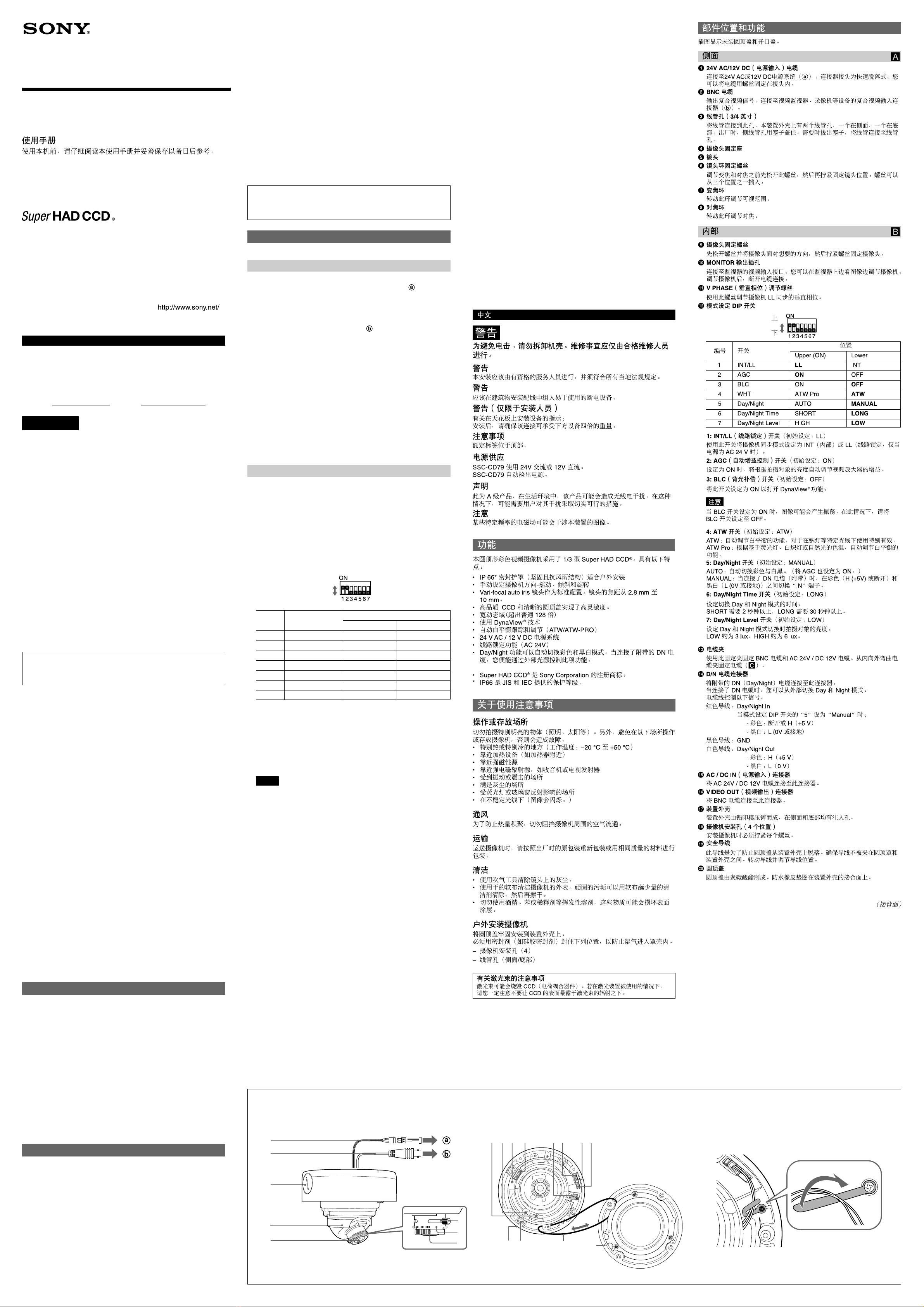
Location and Function of Part
The figure shows the camera without the dome casing and slit cover.
Side A
124V AC/12V DC (power input) cable
Connect to a 24V AC or 12V DC power supply system ( ). The
connector tip is a quick-disconnect type. You can screw the cables in
the tip.
2BNC cable
Outputs a composite video signal. Connect to a composite video input
connector of a video monitor, VCR, etc ( ).
3Conduit holes (3/4 inch)
Connect a pipe to this hole. There are two conduit holes on the unit
casing, one on the side and one at the bottom. The cover plug is
installed in the side conduit hole at the factory. Remove the plug as
needed and connect the pipe to the hole.
4Camera head holder
5Lens
6Lens ring fixing screw
Loosen this screw before adjusting the zoom and focus, then tighten it
to fix the lens position. The screw can be inserted at one of three
points.
7Zoom ring
Turn this ring to adjust the field of view.
8Focus ring
Turn this ring to adjust the focus.
Inside B
9Camera head fixing screw
First loose the screw and face the camera head to the desired
direction, then tighten the screw to fix it.
0MONITOR out jack
Connect to a video input connector of a monitor. You can adjust the
camera while looking at the image on the monitor. After adjusting the
camera, disconnect the cable.
qa V PHASE (vertical phase) adjustment screw
Use this screw to adjust the vertical phase of cameras synchronized
by LL.
qs Mode setting DIP switch
1: INT/LL (line lock) switch (Initial setting: LL)
Use this switch to set the camera synchronization mode to INT
(internal) or LL (line lock, Only when the power is AC 24 V).
2: AGC (automatic gain control) switch (Initial setting: ON)
Set to ON to adjust the gain of the video amplifier automatically
according to the brightness of the object.
3: BLC (backlight compensation) switch (Initial setting: OFF)
Set this switch to ON to active DynaView®function.
Notes
When BLC switch is set to ON, a hunting may be generated due to a
picture. In this case, set BLC switch to OFF.
4: ATW switch (Initial setting: ATW)
ATW: Automatic adjusting function of the white balance, effective for
use under special light like a sodium lamp.
ATW Pro: Automatic adjusting function of the white balance according
to the color temperature based on a fluorescent light, incandescent
lighting, or natural light.
5: Day/Night switch (Initial setting: MANUAL)
AUTO: Switches color and black-and-white automatically. (Set AGC
also to ON.)
MANUAL: Switches “IN” terminal between color (H (+5V) or open) and
black-and-white (L (0V or GND connection)) when the DN cable
(supplied) is connected.
6: Day/Night Time switch (Initial setting: LONG)
Sets the time for switching Day and Night mode.
SHORT takes more than 2 seconds, and LONG takes more than 30
seconds.
7: Day/Night Level switch (Initial setting: LOW)
Sets the brightness of the object of when Day and Night mode
switches.
LOW is approximately 3 lux and HIGH is approximately 6 lux.
qd Cable clamp
Secure the BNC cable and AC 24V / DC 12V cable with this clamp.
Curl the cable clamp upward from inner side to fix the cables (C).
3-284-915-01 (1)
2007 Sony Corporation Printed in China
Color Video Camera
Operating Instructions
Before operating the unit, please read this manual thoroughly and
retain it for future reference.
Notes on Use
Operating or storage location
Do not shoot an extremely bright object (an illumination, the sun, etc.).
Also, avoid operating or storing the camera in the following locations, as
these can be a cause of a malfunction.
•Extremely hot or cold places (Operating temperature: –20 °C to
+50 °C [–4 °F to +122 °F])
•Close to heating equipment (e.g., near heaters)
•Close to sources of strong magnetism
•Close to sources of powerful electromagnetic radiation, such as radios
or TV transmitters
•Locations subject to vibration or shock
•Dusty locations
•Locations under the influence of fluorescent light or reflection of a
window
•Under an unsteady light (the image will flicker.)
English
Owner’s Record
The model and serial numbers are located on the bottom. Record these
numbers in the spaces provided below.
Refer to these numbers whenever you call upon your Sony dealer
regarding this product.
Model No. Serial No.
AB
SSC-CD79/CD79P
9
ql
0qa qs qgqhqfqd
qj
qk
w;
3
5
2
1
4
8
7
6
WARNING
To avoid electrical shock, do not open the cabinet. Refer
servicing to qualified personnel only.
WARNING
This installation should be made by a qualified service person and should
conform to all local codes.
WARNING
A readily accessible disconnect device shall be incorporated in the
building installation wiring.
WARNING (for Installers only)
Instructions for installing the equipment on the ceiling or the wall:
After the installation, ensure the connection is capable of supporting four
times the weight of the equipment downwards.
CAUTION
The rating label is located on the bottom.
Power Supply
Caution for U.S.A. and Canada
The SSC-CD79 operates on 24V AC or 12V DC.
The SSC-CD79 automatically detects the power.
Use a Class 2 power supply which is UL Listed (in the U.S.A) or CSA-
certified (in Canada).
Caution for other countries
The SSC-CD79/CD79P operates on 24V AC or 12V DC.
The SSC-CD79/CD79P automatically detects the power.
For customers in the U.S.A.
This device complies with Part 15 of the FCC Rules. Operation is
subject to the following two conditions: (1) This device may not cause
harmful interference, and (2) this device must accept any interference
received, including interference that may cause undesired operation.
NOTE: This equipment has been tested and found to comply with the limits for a
Class A digital device, pursuant to part 15 of the FCC Rules. These limits are
designed to provide reasonable protection against harmful interference when the
equipment is operated in a commercial environment. This equipment generates,
uses, and can radiate radio frequency energy and, if not installed and used in
accordance with the instruction manual, may cause harmful interference to radio
communications. Operation of this equipment in a residential area is likely to
cause harmful interference in which case the user will be required to correct the
interference at his own expense.
You are cautioned that any changes or modifications not expressly approved
in this manual could void your authority to operate this equipment.
All interface cables used to connect peripherals must be shielded in order
to comply with the limits for a digital device pursuant to Subpart B of Part
15 of FCC Rules.
For Customers in Canada
This Class A digital apparatus complies with Canadian ICES-003.
Cet appareil numérique de la classe A est conforme à la norme NMB-003
du Canada.
For Customers in Eurpoe
The manufacturer of this product is Sony Corporation, 1-7-1 Konan,
Minato-ku Tokyo, Japan.
The Authorized Representative for EMC and product safety is Sony
Deutschland GmbH, Hedelfinger Strasse 61, 70327 Stuttgart, Germany.
For any service or guarantee matters please refer to the addresses given
in separate service or guarantee documents.
For the customers in Europe, Australia and New Zealand
WARNING
This is a Class A product. In a domestic environment, this product may
cause radio interference in which case the user may be required to take
adequate measures.
In the case that interference should occur, consult your nearest
authorized Sony service facility.
This apparatus shall not be used in the residential area.
ATTENTION
The electromagnetic fields at specific frequencies may influence the
picture of the unit.
Features
This is a dome-shaped color video camera for which the 1/3 type Super
HAD CCD®has been adopted. It has the following features:
•IP 66* sealed enclosure (sturdy and weatherproof structure) suitable for
outdoor installation
•Manual setting of the camera direction – panning, tilting and rotating
•Vari-focal auto iris lens as standard equipment. The focal length of the
lens is from 2.8 mm to 10 mm.
•High quality CCD and clear dome cover enable high sensitivity.
•Wide dynamic range (128 times wider than normal)
•Using DynaView®technology
•Automatic white balance tracking and adjustment (ATW/ATW-PRO)
•24 V AC / 12 V DC power supply system
•Line lock function (24 V AC)
•Day/Night function automatically switches between color and
monochrome modes. You can control this function through an external
source when connecting the supplied DN cable.
•Super HAD CCD®is a registered trademark of Sony Corporation.
*IP66 is a protection grade provided under JIS and IEC.
qf D/N cable connector
Connect the supplied D/N (Day/Night) cable to this connecter.
When the D/N cable is connected, you can switch Day and Night
modes from outside.
The wires of the cable control the following signals.
Red wire: Day/Night In
When the "5" of Mode setting DIP switch is set to "Manual";
- Color: Open or H (+5 V)
- Black and White: L (0V or GND connection )
Black wire: GND
White wire: Day/Night Out
- Color: H (+5 V)
- Black and White: L (0 V)
qg AC / DC IN (power input) connector
Connect an AC 24V / DC 12V cable to this connector.
qh VIDEO OUT (Video out) connector
Connect the BNC cable to this connector.
qj Unit casing
The unit casing is made of die-cast aluminum and has conduit holes
on the side and at the bottom.
qk Camera installation holes (4 positions)
Make sure to tighten the screws securely when installing the camera.
ql Safety cord
This cord prevents the dome casing from falling off the unit casing.
Make sure that the cord does not get caught between the dome casing
and the unit casing. Rotate the cord and adjust the position of the cord.
w; Dome casing
The dome cover is made of polycarbonate. A waterproof rubber gasket
is provided on the joint surface to the unit casing.
(continued on the reverse side)
Upper
Lower
C
No.
1
2
3
4
5
6
7
Switch
INT/LL
AGC
BLC
WHT
Day/Night
Day/Night Time
Day/Night Level
Upper (ON)
LL
ON
ON
ATW Pro
AUTO
SHORT
HIGH
Lower
INT
OFF
OFF
ATW
MANUAL
LONG
LOW
Position
English
Installation
Before Installation
After deciding the direction in which the camera will shoot, make the
required hole (ø 76 to 80 mm (3 to 3 3/20 inches) ) for the connecting
cables using the supplied template. Then decide the four mounting hole
positions to install the bracket. (D)
Installing on the wall
When you install the camera on a wall lengthwise, position the side
conduit hole directly below to prevent moisture from getting inside the
casing. (E)
Mounting screws
The supplied bracket is provided with eight ø 4.5 mm ( 3/16 inch) mounting
holes. Install the bracket on a ceiling or wall with screws through these
four of the eight holes.
The required mounting screws differ depending on the installation location
and its material. (Mounting screws are not supplied.)
Steel wall or ceiling: Use M4 bolts and nuts.
Wood wall or ceiling: Use M4 tapping screws. The panel thickness must
be 15 mm ( 5/8inch) or more.
Concrete wall: Use appropriate anchors, bolts and plugs for concrete
walls.
Junction box: Use screws to match the holes on the junction box.
WARNING
The required mounting screws differ depending on the installation location
and its material. If you do not secure the camera with the appropriate
mounting screws, the camera may fall off.
Installing the Camera
1Remove the dome casing.
Loosen the four dome casing screws with the supplied wrench, and
remove the dome casing.
2Remove the slit cover.
Remove it expanding the slit cover. (F)
3Check the conduit of the cables.
The cables are set up at the factory to pass through the bottom conduit
hole. If you want to use the side conduit hole, perform the following
steps:
1Remove the conduit hole cover.
2Disconnect the cables from the connectors, and pull them out from
the bottom conduit hole.
3Insert the cables through the side conduit hole, and connect the
cables to their respective connectors.
4Attach the conduit hole cover that was removed from the side
conduit hole to the bottom conduit hole.
Notes
• If the bottom conduit hole is dirty, the conduit hole cover cannot be
fixed firmly. In this case, moisture may leak into the casing and this
may cause a malfunction. Wipe off the dust with a soft cloth, and fix
the conduit hole cover firmly.
•Cover the joint part of the pipe/cover with silicon sealant, etc. to
prevent moisture from getting inside the casing.
•Use a pipe/plug with a thread length of 12 mm (1/2in.) or less so that
it does not damage the camera. (G)
4Connect the D/N cable.
When you make Day/Night function active, feed the supplied D/N
cable through the conduit hole, and connect it to the D/N cable
connector of the camera unit. Then, secure it with the cable clamp.
5Install the supplied bracket on the ceiling or wall. (H)
Refer to “Mounting screws” for screws to be used.
6When installing on a ceiling or wall, fix the supplied wire rope to the
camera and the ceiling or wall. (I)
1Fix the wire rope to the screw hole on the bottom of the camera
with the supplied shoulder screw as required.
2Fix the wire rope to the ceiling or wall. (The mounting screw is not
supplied.)
7Attach the camera unit to the bracket with the supplied mounting
screws. (I)
Turn the camera unit to click and fix one of the projections on the
bottom of the camera to the positioning hole of the bracket. There are
four projections with an angle of 90 degrees, so you can select one of
four directions.
WARNING
• If you want to install the camera at a height such as on a ceiling,
entrust the installation to an experienced contractor or installer.
•If you install the camera at a height, ensure that the installation
location and its material are strong enough to withstand a weight of
20 kg (44 lb 1 oz) or more, and then install the camera securely. If
they are not strong enough, the camera may fall and cause serious
injury.
•To prevent the camera from falling, be sure to attach the supplied
wire rope.
•If you install the camera at a height, check periodically, at least once
a year, to ensure that the connection has not loosened. If conditions
warrant, perform this periodic check more frequently.
Note
If you cannot use screws on a ceiling or wall, or if you want to make
the camera less conspicuous, use the YT-ICB45 in-ceiling bracket
(optional) with which you can mount the camera on the ceiling.
For this model, install the camera to the “B” position on the side
brackets of YT-ICB45.
Refer to the Installation Instructions of YT-ICB45 for detail information.
Adjusting the Camera Direction and Coverage
J
1Loosen the camera head fixing screw.
2Adjust the camera to turn the lens in the desired direction.
3Tighten the camera head fixing screw to fix the camera.
4Loosen the lens ring fixing screw.
5Turn the zoom ring to adjust the angle of view.
6Turn the focus ring to adjust the focus.
7Tighten the lens ring fixing screw to fix the zoom and the focus.
8Repeat steps 1to 7until the coverage and the focus are determined.
Notes
•When you adjust the camera head angle without loosening camera
head fixing screw, an internal metallic part may be damaged.
•If the camera head is too heavy to be adjusted, loosen the camera
head fixing screw until it moves freely.
• When the lens is not put in the slit of the camera head holder, the
moving range of the camera head is limited.
•Do not turn the lens more than 360 degrees. As this may damage
the wiring inside.
•There are three screw holes for fixing the lens ring at 120 degree
intervals. If the lens ring fixing screw poses a problem for adjusting
the camera direction and coverage due to the direction of the
camera head, detach the screw and reattach it to another screw
hole, then adjust the camera direction and coverage again.
•When adjusting the angle, be sure that the TOP mark on the camera
head section faces the ceiling. If the camera is installed with the
TOP mark facing the floor, the image appears upside down.
Attaching the Dome Casing K
1Attach the slit cover.
Notes
• The proper position of the slit cover is slightly apart from the camera
mount. Do not push in by force.
•If you cannot attach the slit cover because the barrier of the lens
ring fixing screw prevents it, attach the lens ring fixing screw to
another screw hole. There are three screw holes for the lens ring
fixing screw on the concentric circle.
2Fix the dome casing and the camera unit.
Align the four screw holes on the dome casing with those on the
camera unit, and tighten the screws with the supplied wrench to
secure the dome casing and unit casing.
Typical CCD Phenomena
The following phenomena may appear on the monitor screen while you
are using a CCD color video camera. These phenomena stem from the
high sensitivity of the CCD image sensors, and do not indicate a fault
within the camera.
Vertical smear
A “smear” may appear to extend vertically from very bright subjects, as
shown below.
This phenomenon is common to CCD imaging elements using an interline
transfer system, and is caused when electric charge induced by infrared
radiation deep within the photo sensor is transferred to the resistors.
Aliasing
When shooting fine stripes, straight lines or similar patterns, the lines may
become slightly jagged.
Blemishes
A CCD image sensor consists of an array of individual picture elements
(pixels). A malfunctioning sensor element will show up
as a single pixel blemish in the image. This is generally not a problem.
White speckles
When you shoot a poorly illuminated object at a high temperature, small
white dots may appear all over the entire screen image.
Specifications
Image device 1/3 type interline transfer (Super HAD CCD)
Effective picture elements SSC-CD79:
768 (horizontal) ×494 (vertical)
SSC-CD79P:
752 (horizontal) ×582 (vertical)
Focal length 2.8 to 10 mm
Maximum relative aperture
F1.3
View angle Horizontal: 100.8° (wide) – 27.7° (tele)
Vertical: 73.9° (wide) – 20.8° (tele)
Minimum object distance
0.3 m
Signal system SSC-CD79: NTSC color system
SSC-CD79P: PAL color system
Synchronization system Internal (DC 12 V/AC 24 V)/
Line lock (AC 24 V only) switchable
Horizontal resolution 480 TV lines
Minimum illumination Color: 0.7 lx, F1.3, 50 IRE
Black & White: 0.15 lx, F1.3, 50 IRE
Video output 1.0 Vp-p, 75 ohms, negative sync, BNC cable
Video S/N ratio More than 50 dB (AGC OFF)
White balance ATW/ATW Pro switchable
AGC ON / OFF switchable
BLC (DynaView®)ON / OFF switchable
Monitor output Phono jack
Power supply SSC-CD79: 24 V AC ±10 % / 60Hz,
12 V DC ±10 % (Automatically switched)
SSC-CD79P: 24 V AC ±10 % / 50Hz,
12 V DC ±10 % (Automatically switched)
Power consumption 4.2 W max.
Operating temperature –20 °C to +50 °C (–4 °F to +122 °F)
Storage temperature –40 °C to +60 °C (–40 °F to +140 °F)
Operating humidity 20% to 80%
Storage humidity 20% to 95%
Dimensions (diameter/height) (L)
150 ×119 mm
(5 9/10 ×4 7/10 inches)
Mass Approx. 1.3Kg (2.87 lb 45.86 oz)
Supplied accessories Wrench (1), D/N cable (1), Installation screw
(4), Shoulder screw M4 (1), Wire rope (1),
Template (1), Operating Instructions (1)
Optional accessories In-ceiling bracket YT-ICB45
Design and specifications are subject to change without notice.
Always verify that the unit is operating properly before use. SONY WILL
NOT BE LIABLE FOR DAMAGES OF ANY KIND INCLUDING, BUT NOT
LIMITED TO, COMPENSATION OR REIMBURSEMENT ON ACCOUNT
OF THE LOSS OF PRESENT OR PROSPECTIVE PROFITS DUE TO
FAILURE OF THIS UNIT, EITHER DURING THE WARRANTY PERIOD
OR AFTER EXPIRATION OF THE WARRANTY, OR FOR ANY OTHER
REASON WHATSOEVER.
Regular parts replacement
Some of the parts that make up this product (electrolytic condenser, for
example) need replacing regularly depending on their life expectancies.
The lives of parts differ according to the environment or condition in
which this product is used and the length of time it is used, so we
recommend regular checks.
Consult the dealer from whom you bought it for details.
Video monitor screen Pale vertical smear
Very bright subject (such as
an electric lamp,
fluorescent lamp, sunlight,
or strong reflected light)
D
E
F
I
J
12mm (1/2in.) or less/
G
H
Wire rope
Positioning
Hole/
K
Slit cover/
Bracket/
Ceiling/
Projection/
1, 3
2
4, 7
5
6
Unit: mm (inches)/
85.7 (3 3/8)
46 (1 13/16)
85.7 (3
3
/
8
)
83.5 (3
9
/
32
)
LBottom/
Unit: mm (inches)/
ø150(5 9/10)
119(4
7
/
10
)
Side/
Conduit hole (3/4in.)/
Ceiling/
Position the conduit hole
directly below./
Lens ring fixing
screw holes/
Hole for the
connecting cables
ø76 to 80
(3 to 3 3/20)/
76
80
Hole for
installing the
bracket/
Horizontal
marker/
Vertical marker/
Mounting screws
(not supplied)/
Wire rope/

This manual suits for next models

1

Other Sony Security Camera manuals

Sony SNCVM602R User manual

Sony

Sony SNCVM602R User manual

Sony SNC-DF40P User manual

Sony

Sony SNC-DF40P User manual

Sony IPELA SNC-DF70P User manual

Sony

Sony IPELA SNC-DF70P User manual

Sony IPELA SNC-DF70N User manual

Sony

Sony IPELA SNC-DF70N User manual

Sony Vaio PCGA-UVC11A User manual

Sony

Sony Vaio PCGA-UVC11A User manual

Sony SNC-RZ25N - Network Camera User manual

Sony

Sony SNC-RZ25N - Network Camera User manual

Sony XCL-U1000 User manual

Sony

Sony XCL-U1000 User manual

Sony IPELA SNC-RZ30N User manual

Sony

Sony IPELA SNC-RZ30N User manual

Sony IPELA SNC-HM662 User manual

Sony

Sony IPELA SNC-HM662 User manual

Sony REVDN700-2 User manual

Sony

Sony REVDN700-2 User manual

Sony XCGH280CR User manual

Sony

Sony XCGH280CR User manual

Sony SNC-EM632RC User manual

Sony

Sony SNC-EM632RC User manual

Sony SNCVM600B User manual

Sony

Sony SNCVM600B User manual

Sony SSC-CB564R User manual

Sony

Sony SSC-CB564R User manual

Sony BRC-300P User manual

Sony

Sony BRC-300P User manual

Sony XYSD723IR User manual

Sony

Sony XYSD723IR User manual

Sony SSC-DC174 User manual

Sony

Sony SSC-DC174 User manual

Sony FCBIX45C User manual

Sony

Sony FCBIX45C User manual

Sony HDC2500 User manual

Sony

Sony HDC2500 User manual

Sony IPELA SNC-CH110 User manual

Sony

Sony IPELA SNC-CH110 User manual

Sony Super HAD CCD SSC-CD73VP User manual

Sony

Sony Super HAD CCD SSC-CD73VP User manual

Sony CD39IR-4N1S User manual

Sony

Sony CD39IR-4N1S User manual

Sony SNC-RZ50P User manual

Sony

Sony SNC-RZ50P User manual

Sony SNC-VB600B User manual

Sony

Sony SNC-VB600B User manual

Popular Security Camera manuals by other brands

COP-USA CD260XIRICR-WDR user manual

COP-USA

COP-USA CD260XIRICR-WDR user manual

Velleman CAMIP6 user manual

Velleman

Velleman CAMIP6 user manual

Okina SIR42-352AI Operational manual

Okina

Okina SIR42-352AI Operational manual

Bosch VDN-5085 installation manual

Bosch

Bosch VDN-5085 installation manual

TRENDnet TV-IP743SIC user guide

TRENDnet

TRENDnet TV-IP743SIC user guide

Speco RC-650 Features

Speco

Speco RC-650 Features

Vitek VTD-M2HET2812 manual

Vitek

Vitek VTD-M2HET2812 manual

Sanyo VCC-P9575P installation manual

Sanyo

Sanyo VCC-P9575P installation manual

Alecto DVC-216IP user manual

Alecto

Alecto DVC-216IP user manual

VOLTA VODN4612 user manual

VOLTA

VOLTA VODN4612 user manual

Vitek Transcendent VTD-TND6FPN quick start guide

Vitek

Vitek Transcendent VTD-TND6FPN quick start guide

Digitus DN-16055 user manual

Digitus

Digitus DN-16055 user manual

HD Mask iMini user manual

HD Mask

HD Mask iMini user manual

Moog Videolarm PFDW75C12N Installation and operation instructions

Moog Videolarm

Moog Videolarm PFDW75C12N Installation and operation instructions

Swann PRO-750 user manual

Swann

Swann PRO-750 user manual

DENAVO DHS-700RX user manual

DENAVO

DENAVO DHS-700RX user manual

Orion GST-410 installation manual

Orion

Orion GST-410 installation manual

EverFocus EPA6220 Quick installation guide

EverFocus

EverFocus EPA6220 Quick installation guide

manuals.online logo
manuals.online logoBrands
  • About & Mission
  • Contact us
  • Privacy Policy
  • Terms and Conditions

Copyright 2025 Manuals.Online. All Rights Reserved.