5: Calibrating the speaker settings automatically
?/1
MULTISTEREOGAME
NIGHTMODE
PHONES
MOVIE
A.F.D.
AUTOCAL MIC VIDEO LAUDIOR
VIDEO2 IN
MASTERVOLUMEINPUTSELECTOR
MUSIC
?/1
AUTO CAL MIC
123
46
78
0/10
ENTER
9
SYSTEM STANDBY
TV INPUT
SLEEP DMPORT
VIDEO1 VIDEO2 BD DVD
2CH A.F.D. MOVIE MUSIC
CLEAR
DISPLAY
TV VOL
MASTER VOL
DVD/BD
MENU
AUTO CAL
D.TUNING
D.SKIP
THEATER
SAT TV SA-CD/CD TUNER
?/1
5
>10
O
RETURN/EXIT
TV
?/1
AV
?/1
TOOLS/
OPTIONS
MENU/HOME
AMP MENUMEMORY
MUTING
Input buttons
AUTO CAL
AMP MENU
3: Connecting other components
This is an example of how to connect this receiver and your components. Refer to step 3 and 4 of “Getting started” of the operating instructions supplied
with this receiver for details on other connections and other components.
4: Connect all power cords last
Connect the AC power cord to a wall outlet.
Refer to “Connecting the AC power cord” in the operating instructions supplied with the receiver.
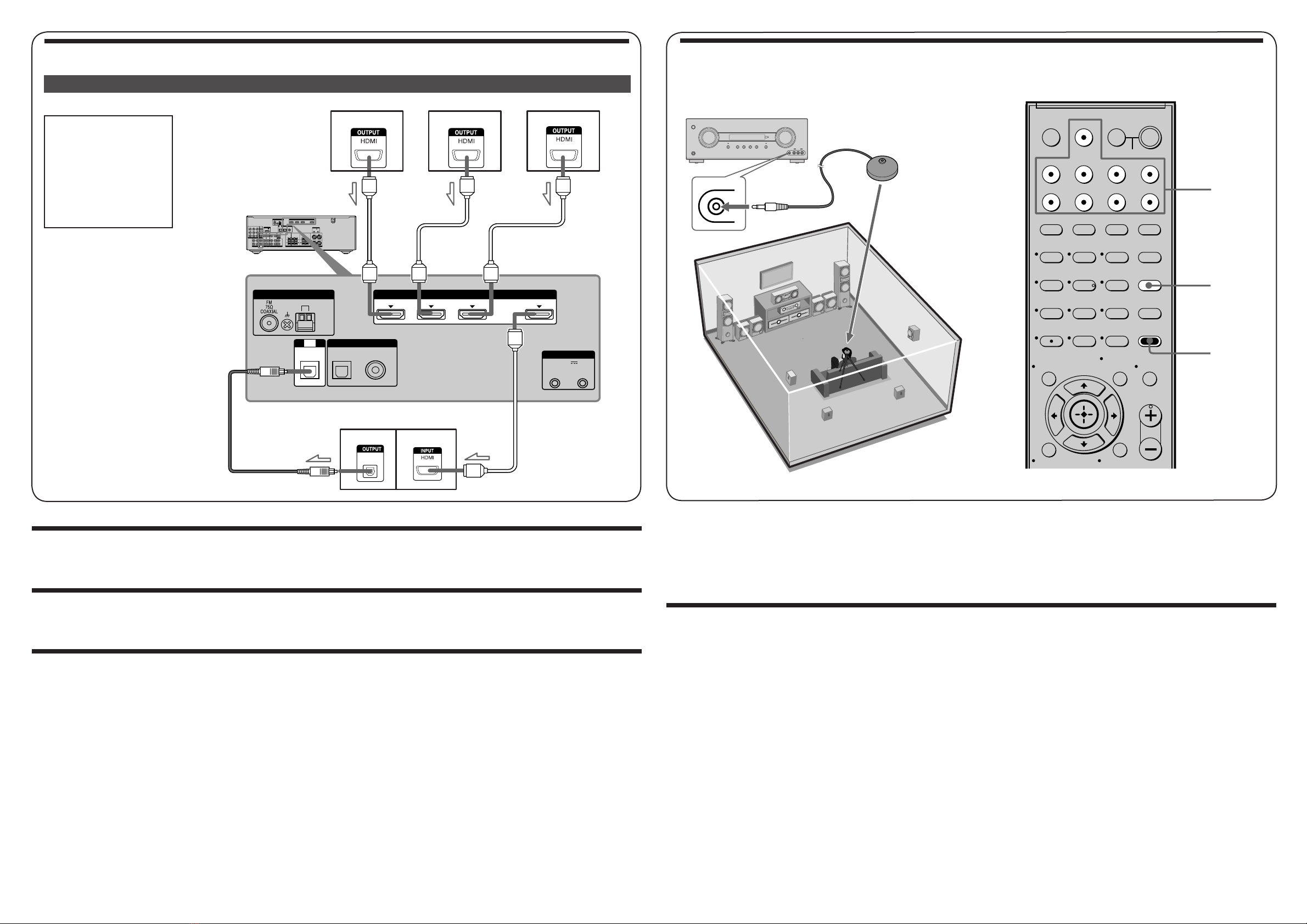
5: Calibrating the speaker settings automatically
You can set up the speakers to obtain the sound you want from all connected speakers automatically by using the Auto Calibration function. The Auto
Calibration function will:
• Check the connection between each speaker and the receiver.
• Adjust the speaker level.
• Measure the distance of each speaker from your listening position.
1Connect the supplied optimizer microphone to the AUTO CAL MIC jack on the receiver.
2Set up the optimizer microphone.
Place the optimizer microphone at your listening position.You can also use a stool or tripod so that the optimizer microphone remains at the same
height as your ears.
3Press AMP MENU, then press AUTO CAL.
The Auto Calibration function starts.
Optimizer microphone (supplied)
Video components
3: Connecting other components
Note
Be sure to change the factory
setting of the DVD input button
on the remote so that you can
use the button to control your
DVD player. For details, see
“Changing button assignments”
in the operating instructions of
the receiver.
DIGITAL (ASSIGNABLE)
SAT IN DVD IN OUT
AM
TV
IN SAT
IN
DVD
IN
DC5V
50mA MAX
OUT OUT
OPTICAL COAXIAL
ANTENNA
SYSTEM CONTROL
DIGITAL
OPTICAL
BD IN
HDMI
L
R
DIGITAL(ASSIGNABLE)
DC5V
0.7AMAX
DMPORT
SATIN
SAT
IN
DVD IN BD IN OUT
AM
Y
P
B
/
C
B
COMPONENTVIDEO
OUT IN
P
R
/
C
R
DVD
IN
VIDEO1
IN
MONITOR
OUT
SA-CD
/
CD
/
CD-R
VIDEO 1
IN
TV
TV
AUDIO
IN
VIDEO
IN
SAT
AUDIO
OUT AUDIO
OUT
VIDEO
OUT
VIDEO
OUT
IN
OPTICAL
AUDIO
IN
VIDEO
IN
SUBWOOFER
MONITOR
AUDIO
IN
VIDEO
IN
BD
SAT
IN
DVD
IN
DC5V
50mAMAX
OUT OUT
OPTICAL COAXIAL
CENTER SURROUND BACK SURROUND
FRONT
L
L
R
RLR
HDMIANTENNA
SPEAKERS
SYSTEMCONTROL
OPTICAL
DHDMI cable
EOptical digital cord
DVD player
TV
Satellite tuner or Set-top box Blu-ray disc player
Cords used for connection (not supplied)
For details on the Auto Calibration function, refer to step 7 of "Getting started" of the operating instructions supplied with this receiver.
Notes
•If there are any obstacles in the path between the optimizer microphone and the speakers, the calibration cannot be performed correctly. Remove any
obstacles from the measurement area to avoid measurement error.
•The Auto Calibration function cannot detect the subwoofer. Therefore, all subwoofer settings will be maintained.
6: Setting up other components
You should set up each component so that the sound is output from the speakers correctly when you playback a connected component. Refer to the
operating instructions supplied with each component.
Note
If no digital signal is input through the COAXIAL or OPTICAL jack on the receiver, “NO INPUT” appears on the display. This is not a malfunction.
414149211_DDW8500_GB_A3.indd 2414149211_DDW8500_GB_A3.indd 2 5/8/2009 11:21:17 AM5/8/2009 11:21:17 AM


