Sony HCD-GNX600 Building instructions

HCD-GNX600
E Model
Australian Model
SERVICE MANUAL
MINI HI-FI COMPONENT SYSTEM
Sony Corporation
Home Audio Division
Published by SonyTechno Create Corporation
9-887-199-01
2006D02-1
© 2006.04
SPECIFICATIONS
Ver.1.0 2006.04
– Continued on next page –
•HCD-GNX600 is the Amplifier,
CD player, tape deck and tuner
section in MHC-GNX600.
Model Name Using Similar Mechanism HCD-GNX800
CD CD Mechanism Type CDM74KFS-F1BD81A
Section Base Unit Name BU-F1BD81A
Optical Pick-up Name KSM-215DCP/C2NP
TAPE Model Name Using Similar Mechanism HCD-GNX800
Section Tape Transport Mechanism Type CWN42FF601
Amplifier section
The following are measured at 120 V, 220 V, 240 VAC,
50/60 Hz
Front speakers
DIN power output (rated) 130 + 130 watts
(6 ohms at 1 kHz, DIN)
Continuous RMS power output (reference)
160 + 160 watts(6 ohms at 1 kHz,
10% THD)
Sub woofer
Continuous RMS power output (reference)
200 watts
(4 ohms at 100 Hz,
10% THD)
TV (AUDIO) IN (phono jack) voltage 250 mV,
impedance 47 kiloohms
MIC (phone jack) sensitivity 1 mV,
impedance 10 kiloohms
Outputs
PHONES (stereo mini jack) accepts headphones of
8 ohms or more
FRONT SPEAKER/SUB WOOFER OUT
Use only the supplied
speaker
Disc player section
System Compact disc and digital
audio system
Laser Semiconductor laser
(λ=780 nm)
Emission duration:
continuous
Laser Output Max. 44.6 µW*
* This output is the value
measured at a distance of
200 mm from the objective
lens surface on the Optical
Pick-up Block with 7 mm
aperture.
Frequency response 2 Hz – 20 kHz (±0.5 dB)
Wave length 780 – 790 nm
Signal-to-noise ratio More than 90 dB
Dynamic range More than 90 dB
Tape deck section
Recording system 4-track 2-channel stereo
Frequency response 50 – 13,000 Hz (±3 dB),
using Sony TYPE I tape
w
w
w
.
x
i
a
o
y
u
1
6
3
.
c
o
m
Q
Q
3
7
6
3
1
5
1
5
0
9
9
2
8
9
4
2
9
8
T
E
L
1
3
9
4
2
2
9
6
5
1
3
9
9
2
8
9
4
2
9
8
0
5
1
5
1
3
6
7
3
Q
Q
TEL 13942296513 QQ 376315150 892498299
http://www.xiaoyu163.com

2
HCD-GNX600
Notes on chip component replacement
•Never reuse a disconnected chip component.
•Notice that the minus side of a tantalum capacitor may be
damaged by heat.
Flexible Circuit Board Repairing
•Keep the temperature of soldering iron around 270˚C
during repairing.
•Do not touch the soldering iron on the same conductor of the
circuit board (within 3 times).
•Be careful not to apply force on the conductor when soldering
or unsoldering.
CAUTION
Use of controls or adjustments or performance of procedures
other than those specified herein may result in hazardous
radiation exposure.
This appliance is classified as
a CLASS 1 LASER product.
This label is located on the rear
exterior.
SAFETY-RELATED COMPONENT WARNING!!
COMPONENTS IDENTIFIED BY MARK 0OR DOTTED LINEWITH
MARK 0ON THE SCHEMATIC DIAGRAMS AND INTHE PARTS
LIST ARE CRITICAL TO SAFE OPERATION. REPLACE THESE
COMPONENTS WITH SONY PARTS WHOSE PART NUMBERS
APPEAR AS SHOWN IN THIS MANUAL OR IN SUPPLEMENTS
PUBLISHED BY SONY.
Unleaded solder
Boards requiring use of unleaded solder are printed with the lead
free mark (LF) indicating the solder contains no lead.
(Caution: Some printed circuit boards may not come printed with
the lead free mark due to their particular size.)
: LEAD FREE MARK
Unleaded solder has the following characteristics.
•Unleadedsolder melts at a temperature about 40°Chigher than
ordinary solder.
Ordinary soldering irons can be used but the iron tip has to be
applied to the solder joint for a slightly longer time.
Soldering irons using a temperature regulator should be set to
about 350°C.
Caution: The printed pattern (copper foil) may peel away if
the heated tip is applied for too long, so be careful!
•Strong viscosity
Unleaded solder is more viscous (sticky, less prone to flow)
than ordinary solder so use caution not to let solder bridges
occur such as on IC pins, etc.
•Usable with ordinary solder
It is best to use only unleaded solder but unleaded solder may
also be added to ordinary solder.
Tuner section
FM stereo, FM/AM superheterodyne tuner
FM tuner section
Tuning range 87.5 – 108.0 MHz
Antenna FM lead antenna
Antenna terminals 75 ohm unbalanced
Intermediate frequency 10.7 MHz
AM tuner section
Tuning range
Latin American models: 530 – 1,710 kHz
(with the interval set at 10 kHz)
531 – 1,710 kHz
(with the interval set at 9 kHz)
Other models: 531 – 1,602 kHz
(with the interval set at 9 kHz)
530 – 1,710 kHz
(with the interval set at 10 kHz)
Antenna AM loop antenna
Antenna terminals External antenna terminal
Intermediate frequency 450 kHz
General
Power requirements
Australian model: 230 – 240 VAC, 50/60 Hz
Argentina model: 220 VAC, 50/60 Hz
Other models: 120 V or 220 – 240 VAC,
50/60 Hz
Adjustable with voltage selector
Power consumption 110 watts
Dimensions (w/h/d) (Approx.) 280 ×326 ×385.5 mm
Mass (Approx.) 6.3 kg
Supplied accessories: Remote Commander (1)
Batteries (2)
AM loop antenna (1)
FM lead antenna (1)
Front speaker pads (8)
Sub woofer pads (4)
Design and specifications are subject to change
without notice.
w
w
w
.
x
i
a
o
y
u
1
6
3
.
c
o
m
Q
Q
3
7
6
3
1
5
1
5
0
9
9
2
8
9
4
2
9
8
T
E
L
1
3
9
4
2
2
9
6
5
1
3
9
9
2
8
9
4
2
9
8
0
5
1
5
1
3
6
7
3
Q
Q
TEL 13942296513 QQ 376315150 892498299
http://www.xiaoyu163.com

3
HCD-GNX600
TABLE OF CONTENTS
1. SERVICING NOTES ................................................ 4
2. GENERAL
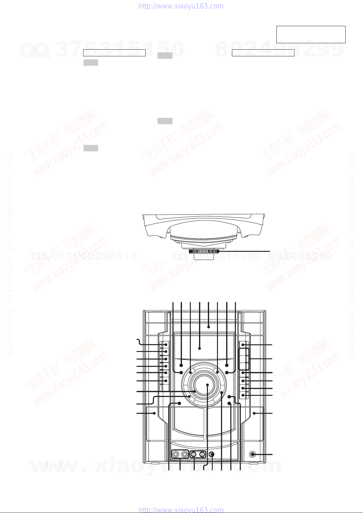
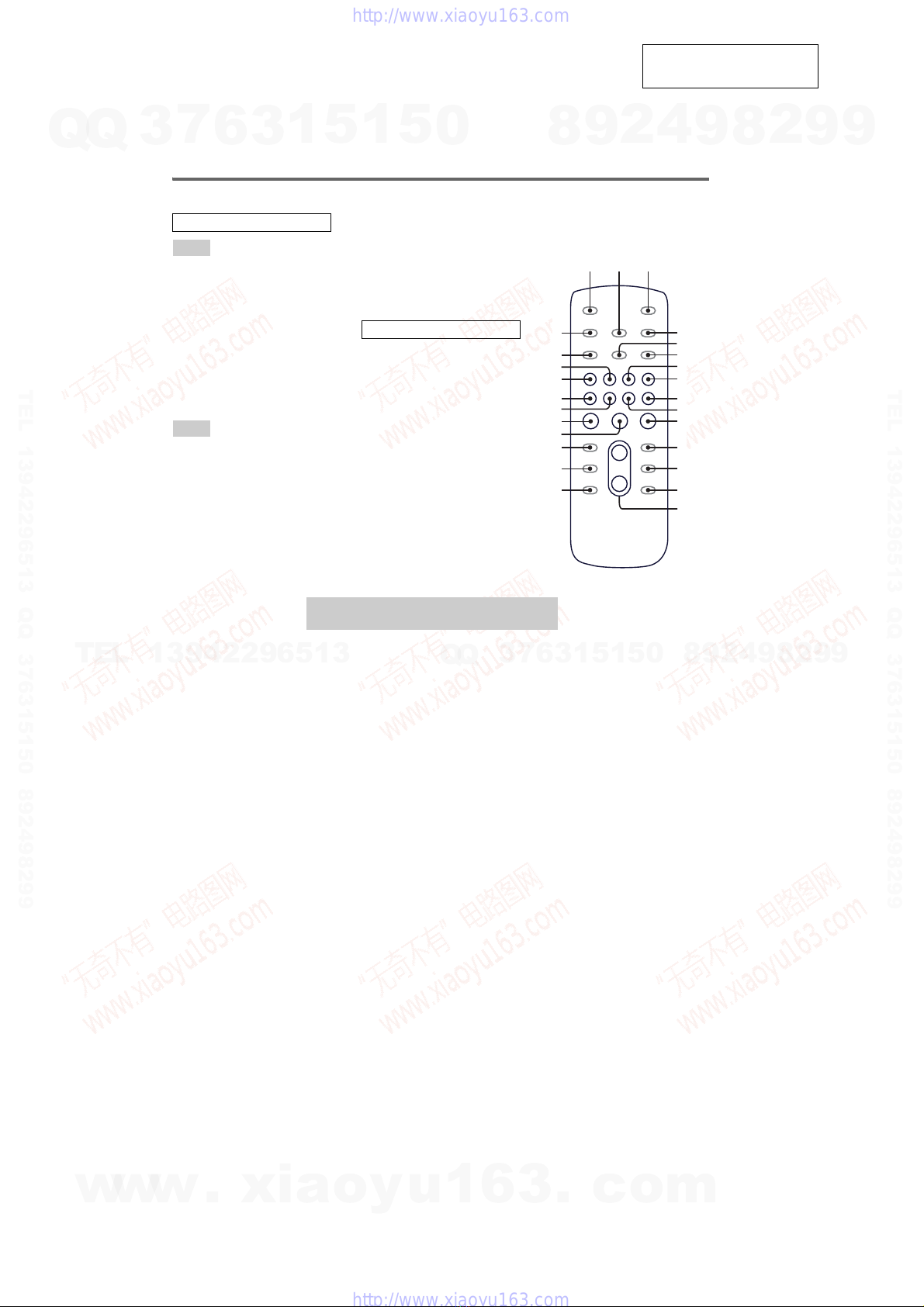
Locating the Controls ...................................................... 5
Setting the Clock ............................................................. 6
3. DISASSEMBLY
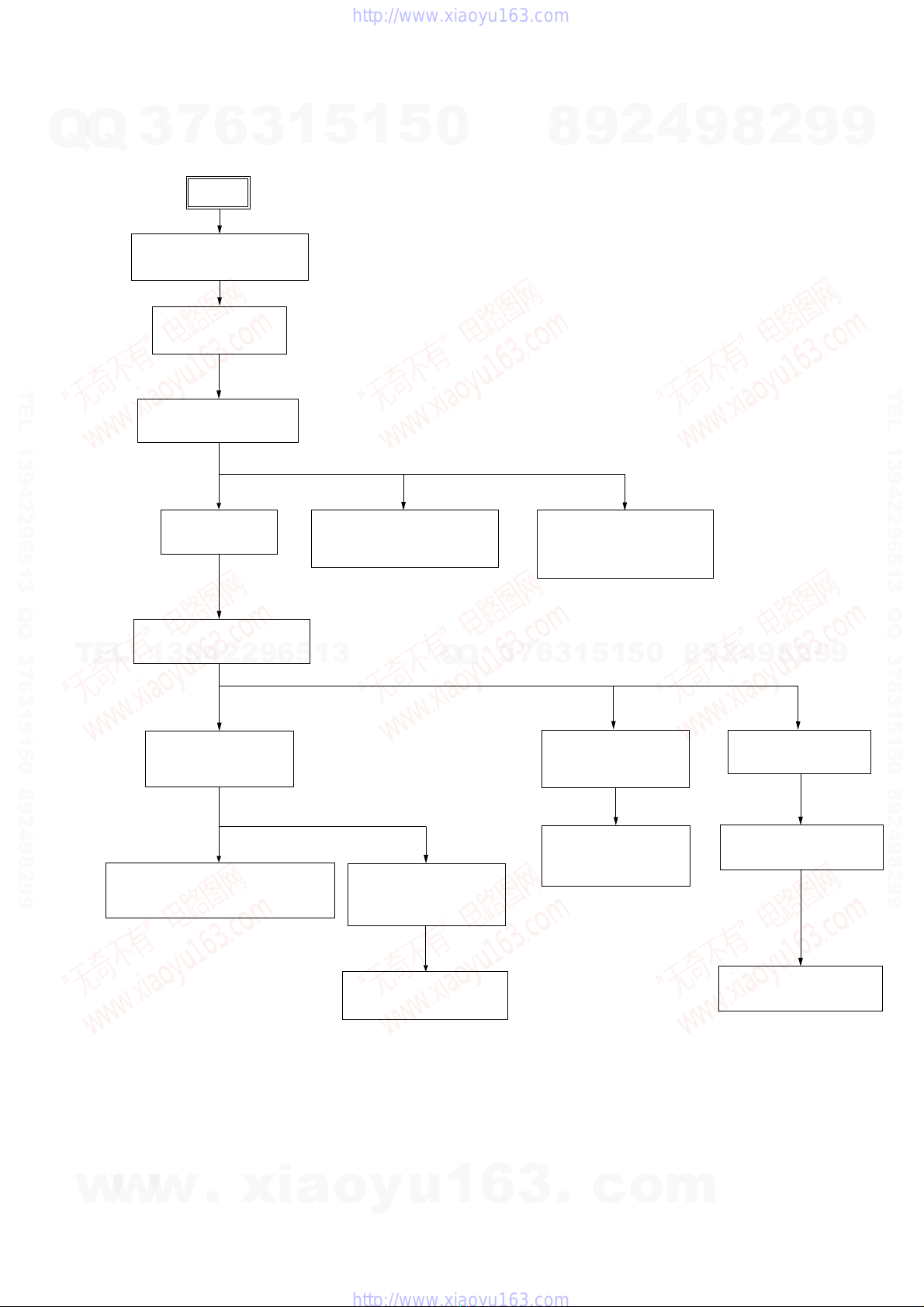
3-1. Disassembly Flow ........................................................... 7
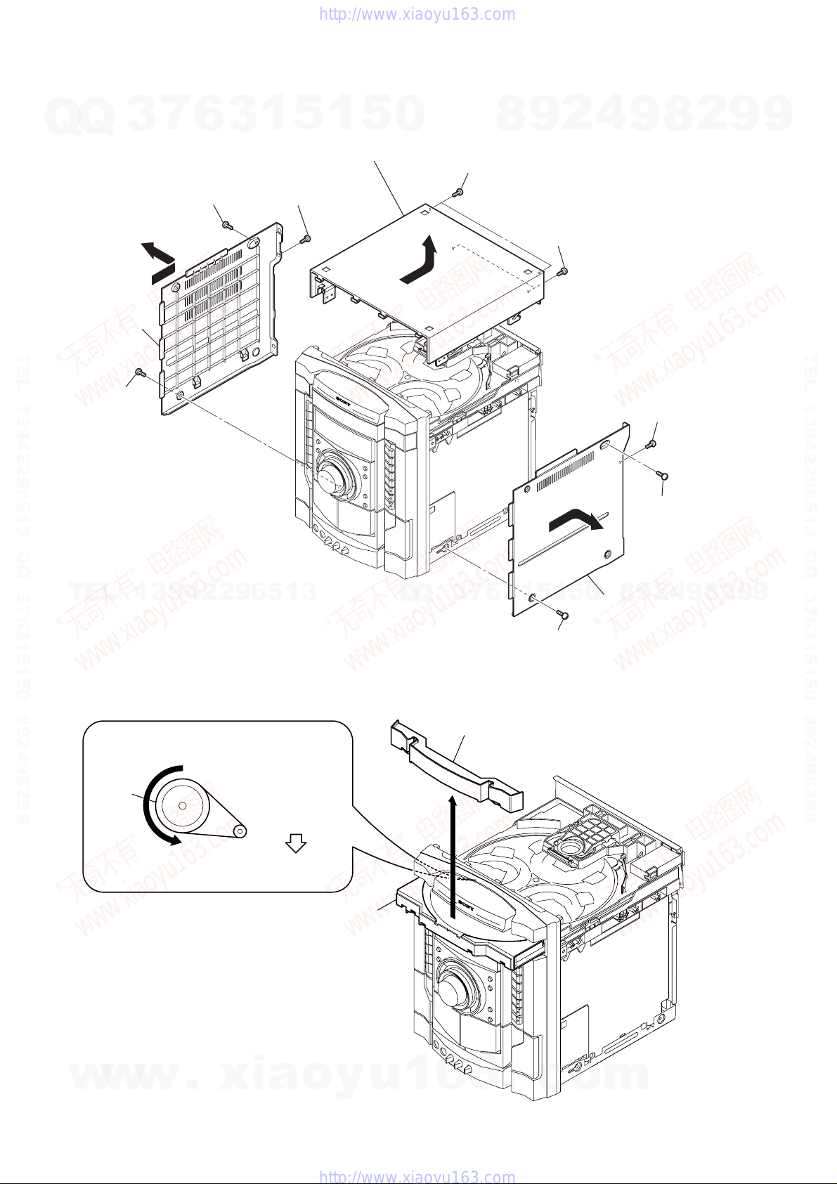
3-2. Side Case, Top Case ........................................................ 8
3-3. Loading Panel.................................................................. 8
3-4. Front Panel Assy.............................................................. 9
3-5. Tuner Pack ....................................................................... 9
3-6. Tape Mechanism Deck, MIC Board ................................ 10
3-7. PANEL Board, IR Board, VOL Board ............................ 10
3-8. CD Mechanism Deck ...................................................... 11
3-9. Back Panel, DC FAN (M891) ......................................... 11
3-10. MAIN Board, ADC Board............................................... 12
3-11. POWER Board, SPEAKER Board.................................. 12
3-12. SMASTER Board............................................................ 13
3-13. DRIVER Board, SW Board............................................. 13
3-14. CD Board, Optical Pick-up ............................................. 14
3-15. SENSOR Board ............................................................... 14
3-16. MOTOR (TB) Board ....................................................... 15
3-17. MOTOR (LD) Board....................................................... 15
4. TEST MODE.............................................................. 16
5. MECHANICAL ADJUSTMENTS ....................... 20
6. ELECTRICAL ADJUSTMENTS
Deck section .................................................................... 20
CD Section ...................................................................... 21
7. DIAGRAMS.................................................................... 24
7-1. Block Diagram – CD Section – ...................................... 26
7-2. Block Diagram – Tape/Tuner Section – ......................... 27
7-3. Block Diagram – Main Section – ................................... 28
7-4. Block Diagram – AMP Section – ................................... 29
7-5. Block Diagram – Display/Power Section –.................... 30
7-6. Printed Wiring Board – CD Board – .............................. 31
7-7. Schematic Diagram – CD Board – ................................. 32
7-8. Printed Wiring Boards – CD Mechanism Sectiom –...... 33
7-9. Schematic Diagram – CD Mechanism Section – ........... 34
7-10. Printed Wiring Board – MAIN Board – ......................... 35
7-11. Schematic Diagram – MAIN Board (1/3) – ................... 36
7-12. Schematic Diagram – MAIN Board (2/3) – ................... 37
7-13. Schematic Diagram – MAIN Board (3/3) – ................... 38
7-14. Printed Wiring Board – PANEL Section – ..................... 39
7-15. Schematic Diagram – PANEL Section – ......................... 40
7-16. Printed Wiring Boards
– MIC,VOL and SPEAKER Boards – ............................ 41
7-17. Schematic Diagram
– MIC,VOL and SPEAKER Boards – ............................ 42
7-18. Printed Wiring Board – ADC Board –............................ 43
7-19. Schematic Diagram – ADC Board – .............................. 44
7-20. Printed Wiring Board – SMASTER Board (Side A)– ... 45
7-21. Printed Wiring Board – SMASTER Board (Side B)– .... 46
7-22. Schematic Diagram – SMASTER Board (1/2)– ............ 47
7-23. Schematic Diagram – SMASTER Board (2/2)– ............ 48
7-24. Printed Wiring Boards – Power Board – ........................ 49
7-25. Schematic Diagram – Power Board – ............................ 50
7-26. IC Pin Function Description............................................ 54
8. EXPLODED VIEWS
8-1. Case (Top), Back Panel Section ...................................... 61
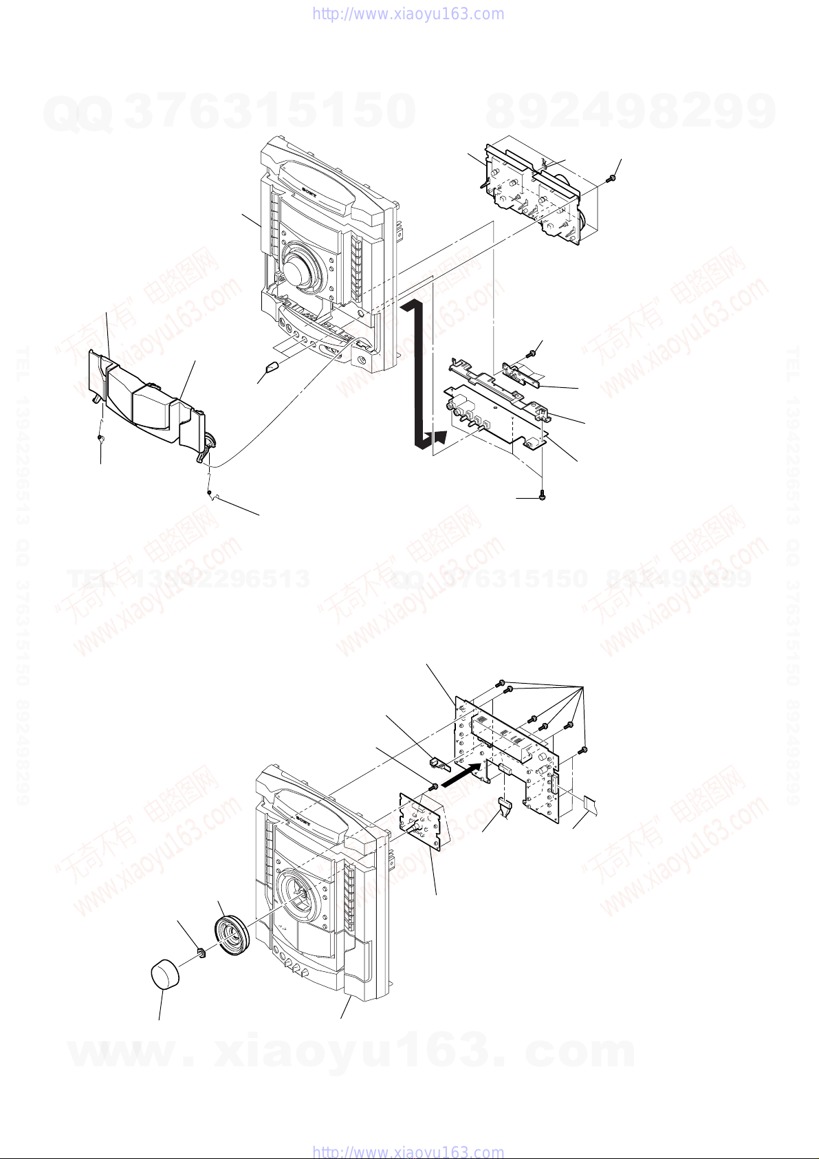
8-2. Front Panel Section ......................................................... 62
8-3. Chassis Section................................................................ 63
8-4. CD Mechanism Deck Section-1 ...................................... 64
8-5. CD Mechanism Deck Section-2 ..................................... 65
9. ELECTRICAL PARTS LIST................................ 66
w
w
w
.
x
i
a
o
y
u
1
6
3
.
c
o
m
Q
Q
3
7
6
3
1
5
1
5
0
9
9
2
8
9
4
2
9
8
T
E
L
1
3
9
4
2
2
9
6
5
1
3
9
9
2
8
9
4
2
9
8
0
5
1
5
1
3
6
7
3
Q
Q
TEL 13942296513 QQ 376315150 892498299
http://www.xiaoyu163.com

4
HCD-GNX600 SECTION 1
SERVICING NOTES
NOTES ON HANDLINGTHE OPTICAL PICK-UP BLOCK
OR BASE UNIT
The laser diode in the optical pick-up block may suffer electrostatic
break-down because of the potential difference generated by the
charged electrostatic load, etc. on clothing and the human body.
During repair, pay attention to electrostatic break-down and also
use the procedure in the printed matter which is included in the
repair parts.
The flexible board is easily damaged and should be handled with
care.
NOTES ON LASER DIODE EMISSION CHECK
The laser beam on this model is concentrated so as to be focused on
the disc reflective surface by the objective lens in the optical pick-
upblock.Therefore, whenchecking thelaser diodeemission, observe
from more than 30 cm away from the objective lens.
LASER DIODE AND FOCUS SEARCH OPERATION CHECK
Carry out the “S curve check” in “CD section adjustment” and check
that the S curve waveform is output several times.
•MODEL IDENTIFICATION
– Back Panel –
MODEL PART No.
E2 model 2-658-970-0[]
AUS model 2-658-970-2[]
E3 model 2-658-970-3[]
E51 model 2-658-970-4[]
AR model 2-658-970-5[]
•Abbreviation
AR : Argentina model
AUS : Australian model
E2 : 120 VAC Area in E model
E3 : 240 VAC Area in E model
E51 : Chilean and Peruvian model
PART No.
w
w
w
.
x
i
a
o
y
u
1
6
3
.
c
o
m
Q
Q
3
7
6
3
1
5
1
5
0
9
9
2
8
9
4
2
9
8
T
E
L
1
3
9
4
2
2
9
6
5
1
3
9
9
2
8
9
4
2
9
8
0
5
1
5
1
3
6
7
3
Q
Q
TEL 13942296513 QQ 376315150 892498299
http://www.xiaoyu163.com

5
HCD-GNX600
SECTION 2
GENERAL This section is extracted
from instruction manual.
LOCATINGTHE CONTROLS
ALBUM + qk
ALBUM – ql
CD es
CD SYNC 8
Deck A wh
Deck B qh
DIRECTION wg
DISC 1 ~ 3 qa
DISC SKIP/EX-CHANGE qs
Disc tray 6
DISPLAY 3
Display 5
ECHO LEVEL wa
EQ BAND/MEMORY 4
GROOVE w;
ILLUMINATION/
SUB WOOFER LEVEL 2
MASTER VOLUME ws
MIC 1/2 (jack) wf
MIC 1/2 LEVEL wd
MP3 BOOSTER 7
PHONES (jack) qj
POWER ILLUMINATOR wk
PRESET EQ wj
REC PAUSE/START 9
SUB WOOFER ON/OFF ed
TAPE A/B e;
Tape lid qh, wh
TUNER/BAND ea
TV wl
?/1 (power) ef
ZOPEN/CLOSE q;
N (play) qd
. OPERATION DIAL >
(forward/gobackward)1
M(fast forward) qk
m(rewind) ql
X(pause) qf
x(stop) qg
PUSH Z (Eject A) wh
PUSH Z(Eject B) qh
ALPHABETICAL ORDER
A-D
E-L
M-R
S-Z
SYMBOLS
Top Panel
Front Panel
1
54326
789
qd
qf
qg
q;
qa
qs
qh
w
g
wh
wj
wl
e;
q
k
w
d
q
l
w
f
w
s
w
;
ea
ed
ef
es
w
a
wk
qj
w
w
w
.
x
i
a
o
y
u
1
6
3
.
c
o
m
Q
Q
3
7
6
3
1
5
1
5
0
9
9
2
8
9
4
2
9
8
T
E
L
1
3
9
4
2
2
9
6
5
1
3
9
9
2
8
9
4
2
9
8
0
5
1
5
1
3
6
7
3
Q
Q
TEL 13942296513 QQ 376315150 892498299
http://www.xiaoyu163.com

6
HCD-GNX600 This section is extracted
from instruction manual.
Remote control
ALBUM + qf
ALBUM – qh
CD wf
CLEAR qk
CLOCK/TIMER SELECT 2
CLOCK/TIMER SET 4
DISC SKIP qd
DISPLAY wh
ENTER qs
EQ qj
FM MODE 6
FUNCTION 8
PLAY MODE 5
REPEAT 6
SLEEP 1
TAPE wd
TUNER/BAND 7
TUNER MEMORY wg
TUNING MODE 5
VOLUME +/– qg
The + button has a tactile dot.*
?/1 (power) 3
x(stop) qa
29, 31)
X(pause) ql
N (play) w;
–.(go backward) ws
>+ (go forward) wa
m(rewind) q;
M(fast forward) 9
*Usethe tactile dot as a reference
when operating the system.
ALPHABETICAL ORDER
A – E
F – Z
SYMBOLS
7
5
q;
qg
qh
qj
qk
w;
ws
wd
wg
wh
qf
qd
qs
qa
9
8
6
4
3
12
ql
wa
wf
Use buttons on the remote for the operation.
1
Press ?/1 to turn on the system.
2
Press CLOCK/TIMER SET.
“CLOCK” appears in the display. Then, the
hour indication flashes in the display.
3
Press –.or >+repeatedly to set
the hour.
4
Press ENTER.
The minute indication flashes in the
display.
5
Press –.or >+ repeatedly to set
the minute.
6
Press ENTER.
The clock starts functioning.
To adjust the clock
1
Press CLOCK/TIMER SET.
“SET” appears in the display, then “PLAY
SET” flashes in the display.
2
Press –.or >+ repeatedly to select
“CLOCK SET”, then press ENTER.
The hour indication flashes in the display.
3
Do the same procedures as step 3 to 6
above.
Notes
The clock settings are canceled when you disconnect
the power cord or if a power failure occurs.
You cannot set the clock in Power Saving Mode
Setting the clock
w
w
w
.
x
i
a
o
y
u
1
6
3
.
c
o
m
Q
Q
3
7
6
3
1
5
1
5
0
9
9
2
8
9
4
2
9
8
T
E
L
1
3
9
4
2
2
9
6
5
1
3
9
9
2
8
9
4
2
9
8
0
5
1
5
1
3
6
7
3
Q
Q
TEL 13942296513 QQ 376315150 892498299
http://www.xiaoyu163.com

7
HCD-GNX600
SECTION 3
DISASSEMBLY
• This set can be disassembled in the order shown below.
3-1. DISASSEMBLY FLOW
3-2.SIDE CASE, TOP CASE
(Page 8)
3-3.LOADING PANEL
(Page 8)
3-4.FRONT PANEL ASSY
(Page 9)
3-5.TUNER PACK
(Page 9)
3-10. MAIN BOARD,
ADC BOARD
(Page 12)
3-8.CD MECHANISM DECK
(Page 11)
3-7.PANEL BOARD,
IR BOARD,
VOL BOARD
(Page 10)
3-6.TAPE MECHANISM DECK,
MIC BOARD
(Page 10)
3-13.DRIVER BOARD,
SW BOARD
(Page 13)
3-11.POWER BOARD,
SPEAKER BOARD
(Page 12)
3-16.MOTOR (TB) BOARD
(Page 15)
3-17.MOTOR (LD) BOARD
(Page 15)
3-15.SENSOR BOARD
(Page 14)
3-12.SMASTER BOARD,
(Page 13)
3-9.BACK PANEL,
DC FAN (M981)
(Page 11)
3-14.CD BOARD,
OPTICAL PIC-UP
(Page 14)
SET
w
w
w
.
x
i
a
o
y
u
1
6
3
.
c
o
m
Q
Q
3
7
6
3
1
5
1
5
0
9
9
2
8
9
4
2
9
8
T
E
L
1
3
9
4
2
2
9
6
5
1
3
9
9
2
8
9
4
2
9
8
0
5
1
5
1
3
6
7
3
Q
Q
TEL 13942296513 QQ 376315150 892498299
http://www.xiaoyu163.com

8
HCD-GNX600
Note: Follow the disassembly procedure in the numerical order given.
3-2. SIDE CASE,TOP CASE
3-3. LOADING PANEL
2
screw
(case 3 TP2)
(3
×
12)
1
screw (case 3 TP2)
(3
×
8)
4
9
qd
3
screw
(+BVTP 3
×
8)
5
case (side-R)
6
screw
(case 3 TP2)
(3
×
8)
7
screw
(case 3 TP2)
(3
×
12)
8
screw
(+BVTP 3
×
8)
0
case (side-L)
qs
two screws
(+BVTP 3
×
8)
qa
two tapping screws
qf
case (top)
CD mechanism deck (CDM74KFS-F1BD81A)
1
Turn the pulley to the arrow direction.
Front side
Pulley
2
Pull out disc tray.
3
4
loading panel
w
w
w
.
x
i
a
o
y
u
1
6
3
.
c
o
m
Q
Q
3
7
6
3
1
5
1
5
0
9
9
2
8
9
4
2
9
8
T
E
L
1
3
9
4
2
2
9
6
5
1
3
9
9
2
8
9
4
2
9
8
0
5
1
5
1
3
6
7
3
Q
Q
TEL 13942296513 QQ 376315150 892498299
http://www.xiaoyu163.com

9
HCD-GNX600
3-4. FRONT PANEL ASSY
3-5.TUNER PACK
1
two screws
(+BVTT 3
×
6
)
2
wire (flat type)
(CN1)
3
tuner pack
1
four screws
(+BVTP 3
×
8)
2
tapping screw
3
tapping screw
4
front panel assy
5
wire (flat type)
(CN201)
6
wire (flat type)
(CN509)
7
connector
(CN121)
q;
connector
(CN503)
8
connector
(CN131)
9
connector
(CN205)
w
w
w
.
x
i
a
o
y
u
1
6
3
.
c
o
m
Q
Q
3
7
6
3
1
5
1
5
0
9
9
2
8
9
4
2
9
8
T
E
L
1
3
9
4
2
2
9
6
5
1
3
9
9
2
8
9
4
2
9
8
0
5
1
5
1
3
6
7
3
Q
Q
TEL 13942296513 QQ 376315150 892498299
http://www.xiaoyu163.com

10
HCD-GNX600
3-6.TAPE MECHANISM DECK, MIC BOARD
3-7. PANEL BOARD, IR BOARD,VOL BOARD
1
six screws
(+BVTP2.6)
8
four screws
(+BVTP2.6)
qa
three screws
(+BVTP3
×
8)
0
9
bracket
(pivot)
qs
bracket
(TC)
qd
MIC board
2
tape mechanism deck
3
spring (R)
5
holder (TC-R)
7
three
mic knobs
6
holder (TC-L)
4
splring (L)
front panel
lug
7
knob (vol)
9
knob jog assy
8
accessory nut
front panel
0
VOL board
5
PANEL board
2
6
IR board
7
four screws
(+BVTP2.6)
1
eighteen screws
(+BVTP2.6)
3
wire (flat type)
(CN1402)
4
connector
(CN1452)
w
w
w
.
x
i
a
o
y
u
1
6
3
.
c
o
m
Q
Q
3
7
6
3
1
5
1
5
0
9
9
2
8
9
4
2
9
8
T
E
L
1
3
9
4
2
2
9
6
5
1
3
9
9
2
8
9
4
2
9
8
0
5
1
5
1
3
6
7
3
Q
Q
TEL 13942296513 QQ 376315150 892498299
http://www.xiaoyu163.com

11
HCD-GNX600
3-8. CD MECHANISM DECK
MAIN board
1
CD mechanism deck
3
wire (flat type)
(CN701)
2
wire (flat type)
(CN351)
2
three screws
(+BVTP 3
×
8)
3
three screws
(+BVTP 3
×
8)
1
screw
(+BVTP 3
×
8)
4
screw
(+BVTP 3
×
8)
5
two screws
(+BVTP 3
×
8)
7
two screws
(+BVTP 3
×
8
)
9
connector
(CN580)
6
back panel
8
DC fan
(M891)
3-9. BACK PANEL, DC FAN (M891)
w
w
w
.
x
i
a
o
y
u
1
6
3
.
c
o
m
Q
Q
3
7
6
3
1
5
1
5
0
9
9
2
8
9
4
2
9
8
T
E
L
1
3
9
4
2
2
9
6
5
1
3
9
9
2
8
9
4
2
9
8
0
5
1
5
1
3
6
7
3
Q
Q
TEL 13942296513 QQ 376315150 892498299
http://www.xiaoyu163.com

12
HCD-GNX600
3-11. POWER BOARD, SPEAKER BOARD
3
two screws
(+BVTT 3
×
6)
4
two screws
(+BVTP 3
×
8)
2
connector
(CN501)
7
connecto
r
(CN590)
8
board to board connector
(CN381,CN01)
5
shield plate (TC MAIN)
6
MAIN board
9
ADC board
1
wire (flat type)
(CN105)
wa
two screws
(+BVTP 3
×
8)
7
three screws
(+BVTP 3
×
8)
9
two screws
(+BVTP 3
×
8)
qa
tapping screw
qg
screw
(+BVTP 3
×
8)
qh
three screws
(+BVTP 3
×
8)
qk
three screws (+BVTP 3
×
8)
8
bracket (support top)
qs
bracket (support pwb)
qj
bracket (SMPS 5ch)
ql
bracket (SMPS -B5)
qf
bracket (trans 5ch)
ws
SPEAKER board
w;
POWER board
qd
two tapping screws
q;
bracket
(support front)
1
screw
(+BVTT 3
×
6)
3
2
three screws
(+BVTT 3
×
6)
4
connector
(CNP1100)
6
connector
(CN1200)
5
connector
(CN1101)
3-10. MAIN BOARD, ADC BOARD
w
w
w
.
x
i
a
o
y
u
1
6
3
.
c
o
m
Q
Q
3
7
6
3
1
5
1
5
0
9
9
2
8
9
4
2
9
8
T
E
L
1
3
9
4
2
2
9
6
5
1
3
9
9
2
8
9
4
2
9
8
0
5
1
5
1
3
6
7
3
Q
Q
TEL 13942296513 QQ 376315150 892498299
http://www.xiaoyu163.com

13
HCD-GNX600
3-13. DRIVER BOARD, SW BOARD
3-12. SMASTER BOARD
3
two screws
(+BVTT 3
×
6)
1
two screws
(+BVTT 3
×
6)
2
heat sink (SMAS)
5
SMASTER board
4
three screws
(+BVTT 3
×
6)
5
connector (CN703)
2
cover (CDM)
6
DRIVER
board
8
SW board
4
wire (flat type) (CN702)
3
two
screws
(+BTTP (M2.6))
1
three
screws
(+BVTP 3
×
10
)
7
screw
(+BTTP (M2.6))
w
w
w
.
x
i
a
o
y
u
1
6
3
.
c
o
m
Q
Q
3
7
6
3
1
5
1
5
0
9
9
2
8
9
4
2
9
8
T
E
L
1
3
9
4
2
2
9
6
5
1
3
9
9
2
8
9
4
2
9
8
0
5
1
5
1
3
6
7
3
Q
Q
TEL 13942296513 QQ 376315150 892498299
http://www.xiaoyu163.com

14
HCD-GNX600
3-14. CD BOARD, OPTICAL PICK-UP
3-15. SENSOR BOARD
4
two
coil springs
(insulator)
7
two
coil springs
(insulator)
5
two
insulators
8
two
insulators
q;
s
crew (+BVTP 2.6 (3CR))
2
h
older (213) ASSY
qa
Remove the four solderings of motor.
qs
wire (flat type) (CN101)
qd
CD
board
qf
optical pick-up
(KSM-215DCP/C2NP)
1
floating
screw
(+PTPWH M2.6)
3
two floating
screws
(+PTPWH M2.6)
6
two floating
screws
(+PTPWH M2.6)
9
2
t
ray
3
b
elt (table)
5
p
ulley (table)
8
s
crew
(+BTTP (M2.6))
0
SENSOR board
7
g
ear (geneva)
9
connector
(
CN731)
1
floating
screw
(+PTPWH M2.6)
6
floating
screw
(+PTPWH M2.6)
4
floating
screw
(+PTPWH M2.6)
w
w
w
.
x
i
a
o
y
u
1
6
3
.
c
o
m
Q
Q
3
7
6
3
1
5
1
5
0
9
9
2
8
9
4
2
9
8
T
E
L
1
3
9
4
2
2
9
6
5
1
3
9
9
2
8
9
4
2
9
8
0
5
1
5
1
3
6
7
3
Q
Q
TEL 13942296513 QQ 376315150 892498299
http://www.xiaoyu163.com

15
HCD-GNX600
3-16. MOTOR (TB) BOARD
3-17. MOTOR (LD) BOARD
6
Remove the two solderings of motor.
8
MOTOR (TB) board
7
t
able motor assy (M741)
5
two
screws
(+BTTP (M2.6))
4
3
wire (flat type) 5 core (CN742)
1
stopper
2
stopper
4
Remove the two solderings of motor.
3
MOTOR (LD) board
1
b
elt (loading)
5
l
oading motor assy (M751)
2
two
screws
(+BTTP (M2.6))
w
w
w
.
x
i
a
o
y
u
1
6
3
.
c
o
m
Q
Q
3
7
6
3
1
5
1
5
0
9
9
2
8
9
4
2
9
8
T
E
L
1
3
9
4
2
2
9
6
5
1
3
9
9
2
8
9
4
2
9
8
0
5
1
5
1
3
6
7
3
Q
Q
TEL 13942296513 QQ 376315150 892498299
http://www.xiaoyu163.com

16
HCD-GNX600
[COMMON TEST MODE]
•Thismode isused to check operations of the respectivesections
of Amplifier and Tape.
Procedure:
* To enter Common Test Mode
1. Press xbutton, [ILLUMINATION] button and [DISC 3]
button simultaneously.
2. The CD ring indicators and line below CD ring indicator flash
synchronously on the fluorescent indicator tube. The function
is changed to TV.
* Check of Amplifier
1. Press [EQ BAND/MEMORY] button repeatedly until a message
“GEQ MAX” appears on the fluorescent indicator tube. GEQ
increases to its maximum.
2. Press [EQ BAND/MEMORY] button repeatedly until a message
“GEQ MIN” appears on the fluorescent indicator tube. GEQ
decreases to its minimum.
3. Press [EQ BAND/MEMORY] button repeatedly until a message
“GEQ FLAT” appears on the fluorescent indicator tube. GEQ
is set to flat.
4. When the [MASTER VOLUME] knob is turned clockwise even
slightly, the sound volume increases to its maximum and a
message “VOLUME MAX” appears on the fluorescent
indicator tube.
5. When the [MASTER VOLUME] knob is turned counter-
clockwise even slightly, the sound volume decreases to its
minimum and a message “VOLUME MIN” appears on the
fluorescent indicator tube.
* Tape function
1. When a tape is inserted in Deck B and recording is started, the
function is changed to TV automatically. When [CD SYNC]
button is pressed during recording in function, ALC
(Automatic Logic Control) is turned on.
2. During recording, press
m
button will stop the recording
and the function is changed to TAPE B and rewind the tape in
Deck B until the recording start position and playback of the
tape in Deck B is started. If the [REC PAUSE/ START] button
is pressed for a pause and pressed again to resume recording
during recording time, when the tape is rewind, the tape will
be rewind until the position where the pause is applied.
* To release from Common Test mode.
1. To release this mode, press ?/1 button.
2. The cold reset is enforced at the same time.
[COLD RESET]
•The cold reset clears all data including preset data stored in
the RAM to initial conditions. Execute this mode when
returning the set to the customer.
Procedure:
1. Press button to turn on the set.
2. Press xbutton, [ILLUMINATION/SUB WOOFER LEVEL]
button, and ?/1 button simultaneously.
3. The message “COLD RESET” appears on the fluorescent
indicator tube. then, the fluorescent indicator tube becomes
blank for a while, and the set is reset.
[PANELTEST MODE]
•This mode is used to check the fluorescent indicator tube,
LEDs, buttons, MASTER VOLUME knob, model,
destination, software version and VACS level.
Procedure:
1. Press xbutton, [ILLUMINATION] button and [DISC 2]
button simultaneously.
2. AllLEDs andsegments in fluorescent indicator tube are lighted
up. All LEDs are lighted up in red color except the SUB
WOOFER ON/OFF LED (green).
3. When you want to enter to the software version display mode,
press [DISC 1] button. The model infomation is displayed.
Press [DISC 1] button again to view destination infomation.
4. Each time [DISC 1] button is pressed, the display changes from
MC version, SYS version, UI version, CD version, CDDM
version, CDMA version, CDMB version, BDA version, BDB
version, ST version, TA version, TM version, TC version in
this order, and returns to the model version display.
5. When [DISC 3] button is pressed while the version numbers
are being displayed except model and destination, the date of
the software creation appear. When [DISC 3] button is pressed
again,the displayreturns to the software version display.When
[DISC 1] button is pressed while the date of the software
creation is being displayed, the date of the software creation
is displayed in the same order of software version display.
6. Press [DISC 2] button, the key check mode is activated.
7. In the key check mode, the fluorescent indicator tube displays
“K 0 V0”. Turn the [OPERATION DIAL] clockwise, “K” value
increases by one. Turn the [OPERATION DIAL] counter-
clockwise, “K” value increases by one. Each time a button is
pressed, “K” value increases. Press other buttons on main unit
tocheck whether the button isdetected. However, once abutton
has been pressed, it is no longer taken into account.
“V” value increases in the manner of 0,1, 2, 3 ... if [MASTER
VOLUME] knob is turned clockwise, or it decreases in the
manner of 0, 9, 8, 7 ... if [MASTER VOLUME] knob is turned
counter-clockwise.
8. When [DISC 3] button is pressed after all LEDs and segments
in fluorescent indicator tube light up, the fluorescent indicator
tube displays “VACSA”.Ais VACS level which is trigger by
signal level.
9. When [DISC SKIP/EX-CHANGE] button is pressed after all
LEDs and segments in fluorescent indicator tube light up,
alternate segments in fluorescent indicator tube would light
up.If youpress [DISC SKIP/EX-CHANGE] button again,another
half of alternate segments in fluorescent indicator tube would
light up. When [DISC SKIP/EX-CHANGE] button is pressed
again, all segments lights off. Press [DISC SKIP/EX-CHANGE]
button again would cause all segments lights up.
10. To release from this mode, press three buttons in the same
manner as step 1, or disconnect the power plug.
SECTION 4
TEST MODE
?/1
w
w
w
.
x
i
a
o
y
u
1
6
3
.
c
o
m
Q
Q
3
7
6
3
1
5
1
5
0
9
9
2
8
9
4
2
9
8
T
E
L
1
3
9
4
2
2
9
6
5
1
3
9
9
2
8
9
4
2
9
8
0
5
1
5
1
3
6
7
3
Q
Q
TEL 13942296513 QQ 376315150 892498299
http://www.xiaoyu163.com

17
HCD-GNX600
[VACS ON/OFF]
•This mode is used to switch ON and OFF the VACS (Variable
Attenuation Control System).
Procedure:
1. Press ?/1 button to turn on the set.
2. Press xbutton and [DIRECTION]
button
and [DISC 1]
button
simultaneously.
The message “VACS OFF” or “VACS ON”
appears on the fluorescent indicator tube.
[TUNER STEP CHANGE]
•The step interval of AM channels can be toggled between 9
kHz and 10 kHz.
Procedure:
1. Press ?/1 button to turn on the set.
2. Press [TUNER/BAND] button repeatedly to select the “AM”.
3. Press ?/1 button to turn off the set.
4. Press [ILLUMINATION/SUB WOOFER LEVEL] button and
?/1 button simultaneously. The system will turn on
automatically. The message “AM 9K STEP” or AM 10K
STEP” appears on the fluorescent indicator tube and thus the
channel step is changed.
[CD SERVICE MODE]
•This mode let you move the CD sled motor freely. Use this
mode when you want to clean the optical pick-up.
Procedure:
1. Press ?/1 button to turn on the set.
2. Select CD function.
3. Press xbutton, [ILLUMINATION/SUB WOOFER LEVEL]
button and
ZOPEN/CLOSE
button simultaneously.
4. The CD service mode is activated. The message “SERVICE
MODE” appears on the fluorescent indicator tube.
5. With the CD in stop status, press
M
button to move the
opticalpick-up tooutside track, or press
m
button to move
to inside track. The message “SLED OUT” or “SLED IN”
appears on the fluorescent indicator tube.
6. To turn on or off the laser, press [GROOVE] button. The
message “LD ON” or “LD OFF” appears on the fluorescent
indicator tube.
7. To release from this mode, press ?/1 button.
[CD AGING MODE]
This mode can be used for operation check of CD section.
•If an error occurs, the aging operation would stops and the
status is displayed.
•If there were no error occurs, the aging operation would
continue repeatedly.
Procedure:
1. Press ?/1 button to turn on the set.
2. Select CD function.
3. Load three discs on the disc tray.
4. Press [PLAY MODE] button on the remote repeatedly to select
the “ALL DISCS” mode, and press the [REPEAT] button on
the remote repeatedly to select “REPEAT OFF” mode.
5. Press x button, [ILLUMINATION/SUB WOOFER LEVEL]
button, and[DISC SKIP/EX-CHANGE] button
simultaneously.The CD ring indicator and line below CD
ring indicator turn on afternately to indicate aging mode.
6. Aging operation is started.
7. To release from this mode, press ?/1 button or disconnect
the power plug.
Aging mode sequence:
Start (from disc 1)
Disc chucking
TOC reading
Play first track for 2 seconds
Play last track for 2 seconds
EX-CHANGE open/close
Open the disc tray
Disc skip
Close the disk tray
Change to the next disc
w
w
w
.
x
i
a
o
y
u
1
6
3
.
c
o
m
Q
Q
3
7
6
3
1
5
1
5
0
9
9
2
8
9
4
2
9
8
T
E
L
1
3
9
4
2
2
9
6
5
1
3
9
9
2
8
9
4
2
9
8
0
5
1
5
1
3
6
7
3
Q
Q
TEL 13942296513 QQ 376315150 892498299
http://www.xiaoyu163.com

18
HCD-GNX600
• Display when an error occurred (CD Error Code Mode)
Procedure:
1. Press xbutton, [ILLUMINATION/SUB WOOFER
LEVEL] button and [DISC 1] button simultaneously to
enter the error code display mode.
2. The fluorescent indicator tube displays the number of total
error.
3. Each time m or M button is pressed, display change as
below.
4. To clear the error record, operate the cold reset. (Refer to the
“COLD RESET”)
5. To release from this mode, press the ?/1 button or
disconnect the power plug.
1) Display of total error
EM**: The number of mechanical errors.
ED**: The number of no disc errors after chucking the disc.
2) Display of mechanical errors
M*: The number of mechanical error (“00” is latest one)
(Rotate
>
.
knob in the direction of either to display next
error)
$$: Not used
%%: Loading related error (Second figure is not used)
D: Stopby the problem other than mechanical problemwhile
closing.
E: Stopby the problem other than mechanical problemwhile
opening.
C: Stopby the problem other than mechanical problemwhile
chucking up.
F: Stopby the problem other than mechanical problemwhile
chucking down.
&&: Emerging error
01: Stop while chucking up.
02: Stop while chucking up.
03: Time-out of EX-CHANGE open.
05: Time-out of EX-CHANGE close.
##: Not used
Display
M*$$%%&&##00
3) Display of no disc errors
D*: The number of no disc error (“00” is latest one)
(Rotate
>
.
knob in the direction of either to display next
error)
$$: Error type
01: Focus error
02: GFS error
03: Setup error
%%: Not used
&&:00: No disc judgment without chucking retry.
01: No disc judgment after chucking retry.
##: The state when judged as no disc
01: Stop
02: Setup
03: TOC reading
04: Access
05: Playback
06: Pause
07: Manual search (Play)
08: Manual search (Pause)
[CD REPEAT 5 LIMIT OFF MODE]
•The number of repeat for CD playback is 5 times when the
repeat mode is “REPEAT ALL”. This mode enables CD to
repeat playback for limitless times.
Procedure:
1. Press ?/1 button to turn on the set.
2. Select CD function.
3. Press xbutton, [CD] button and [DISC 1] button
simultaneously to enter the CD repeat 5 limit off mode and
the fluorescent indicator tube displays “LIMIT OFF”.
4. To release from this mode, operate the cold reset. (Refer to
the “COLD RESET”)
[CD SHIP MODE (WITH MEMORY CLEAR)]
•This mode moves the optical pick-up to the position durable
to vibration and clears all data including preset data stored in
the RAM to initial conditions. Use this mode when returning
the set to the customer after repair.
Procedure:
1. Press ?/1 button to turn on the set.
2. Select CD function.
3. Press x
button,
[DIRECTION]
button and
?/1
button
simultaneously.
The set will turn off automatically.
4. After the “STANDBY” blinking display finishes, a message
“MECHA LOCK” is displayed on the fluorescent indicator
tube and the CD ship mode is set.
Display
D*$$%%&&##00
Display
EM**ED**
Display of total error
Mm
>
Display of Mechanical errors
.
direction direction
Mm
>
Display of no disc errors
.
direction direction
w
w
w
.
x
i
a
o
y
u
1
6
3
.
c
o
m
Q
Q
3
7
6
3
1
5
1
5
0
9
9
2
8
9
4
2
9
8
T
E
L
1
3
9
4
2
2
9
6
5
1
3
9
9
2
8
9
4
2
9
8
0
5
1
5
1
3
6
7
3
Q
Q
TEL 13942296513 QQ 376315150 892498299
http://www.xiaoyu163.com

19
HCD-GNX600
[CDTRAY LOCK MODE]
•This mode let you lock the disc tray. When this mode is
activated,the disc tray will notopen when
Z
OPEN/CLOSE
button or [DISC SKIP/EX-CHANGE] button is pressed. The
message “LOCKED” will be displayed on the fluorescent
indicator tube.
Procedure:
1. Press ?/1 button to turn on the set.
2. Select CD function.
3. Press xbutton and
Z
OPEN/CLOSE
button
simultaneously and hold down until “LOCKED” or
“UNLOCKED” displayed on the fluorescent indicator tube
(around 5 seconds).
[TCM OFFLINE MODE]
•This mode prevents set from power off automatically when
TCM is not connected.
Therefore, measurements can be done even when TCM is not
connected during production.
• Procedure:
1. When the set in turned off, press [EQ BAND/MEMORY]
button, [TAPE A/B] button and ?/1 button simultaneously.
The set will turn on automatically.
2. The message “TCM OFFLINE” will be displayed on the
fluorescent indicator tube.
[CD SHIP MODE (WITHOUT MEMORY CLEAR)]
•This mode moves the optical pick-up to the position durable
to vibration. Use this mode when returning the set to the
customer after repair.
Procedure:
1. Press ?/1 button to turn on the set.
2. Select CD function.
3. Press [CD] button and ?/1 button simultaneously. The set
will turn off automatically.
4. After the “STANDBY” blinking display finishes, a message
“MECHA LOCK” is displayed on the fluorescent indicator
tube and the CD ship mode is set.
[CD POWER MANAGE]
•This mode let you switch on or off power supply to the BU
during TUNER function.
• When CD POWER is set to OFF, the power supply to the BU
is cut off during TUNER function. It will increase the time
taken to access CD when function change from TUNER to
CD but it will improve tuner reception.
•When CD POWER is set to ON, the power supply to the BU
is not cut off during TUNER function. It will reduce the time
taken to access CD when function change from TUNER to
CD but it will decrease tuner reception performance.
Procedure:
1. Press ?/1 button to turn on the set.
2. Select CD function.
3. Press ?/1 button to turn off the set.
4. Press xbutton and ?/1 button simultaneously. The set
will turn on automatically.
5. The message “CD POWER ON” or “CD POWER OFF” will
be displayed on the fluorescent indicator tube.
w
w
w
.
x
i
a
o
y
u
1
6
3
.
c
o
m
Q
Q
3
7
6
3
1
5
1
5
0
9
9
2
8
9
4
2
9
8
T
E
L
1
3
9
4
2
2
9
6
5
1
3
9
9
2
8
9
4
2
9
8
0
5
1
5
1
3
6
7
3
Q
Q
TEL 13942296513 QQ 376315150 892498299
http://www.xiaoyu163.com

20
HCD-GNX600
SECTION 5
MECHANICAL ADJUSTMENTS SECTION 6
ELECTRICAL ADJUSTMENTS
Precaution
1. Clean the following parts with a denatured alcohol-moistened
swab:
record/playback heads pinch rollers
erase head rubber belts
capstan idlers
2. Demagnetize the record/playback head with a head
demagnetizer.
3. Do not use a magnetized screwdriver for the adjustments.
4. After the adjustments, apply suitable locking compound to
the parts adjusted.
5. The adjustments should be performed with the rated power
supply voltage unless otherwise noted.
Torque Measurement
2.9 mN • m to 6.9 mN • m
FWD CQ-102C 30 to 70 g • cm
(0.42 – 0.97 oz • inch)
FWD 0.15 mN • m to 0.59 mN • m
back tension CQ-102C 1.6 to 6 g • cm
(0.022 – 0.08 oz • inch)
4.8 mN • m to 16.7 mN • m
FF/REW CQ-201B 49 to 170 g • cm
(0.69 – 2.36 oz • inch)
Mode Torque meter Meter reading
0 dB=0.775 V
DECK SECTION
1. Demagnetize the record/playback head with a head
demagnetizer.
2. Do not use a magnetized screwdriver for the adjustments.
3. After the adjustments, apply suitable locking compound to the
parts adjust.
4. The adjustments should be performed with the rated power
supply voltage unless otherwise noted.
5. The adjustments should be performed in the order given in
this service manual. (As a general rule, playback circuit
adjustment should be completed before performing recording
circuit adjustment.)
6. The adjustments should be performed for both L-CH and R-
CH.
7. Switchesand controlsshould beset asfollows unlessotherwise
specified.
•Test Tape
RECORD/PLAYBACK HEAD AZIMUTH ADJUSTMENT
DECK A DECK B
Note: Perform this adjustments for both decks
Procedure:
1. Mode: Playback
Tape Signal Used for
P-4-A100 10 kHz, –10 dB Azimuth Adjustment
set
MAIN board
CN121
Pin
3
(L-CH)
Pin
1
(R-CH)
MAIN board
CN121
Pin
2
(GND)
+
–
level meter
test tape
P-4-A100
(10 kHz, –10 dB)
w
w
w
.
x
i
a
o
y
u
1
6
3
.
c
o
m
Q
Q
3
7
6
3
1
5
1
5
0
9
9
2
8
9
4
2
9
8
T
E
L
1
3
9
4
2
2
9
6
5
1
3
9
9
2
8
9
4
2
9
8
0
5
1
5
1
3
6
7
3
Q
Q
TEL 13942296513 QQ 376315150 892498299
http://www.xiaoyu163.com
Other manuals for HCD-GNX600
1
Table of contents
Other Sony Stereo System manuals

Sony
Sony HCD-E301 User manual

Sony
Sony HCD-GTR33 User manual

Sony
Sony MHC-V83D User manual

Sony
Sony HCD-VZ50MD User manual

Sony
Sony ZS-D10 Marketing Specifications & Features User manual

Sony
Sony ZS-PS20CP User manual

Sony
Sony LBT-DR5 User manual

Sony
Sony MHC-W77AV User manual

Sony
Sony LBT-XGR66 User manual

Sony
Sony MHC-M20 User manual

Sony
Sony MHC-MG510AV User manual

Sony
Sony CMT-WS2D User manual

Sony
Sony TA-EX5 User manual

Sony
Sony WHG-SLK1i - Audio System Component User manual

Sony
Sony H.ear go SRS-HG1 Reference guide

Sony
Sony MHC-GN770 User manual

Sony
Sony CMT-FX250 User manual

Sony
Sony HCD-H1200 User manual

Sony
Sony HCD-GR5 User manual

Sony
Sony CX-LEM200 User manual