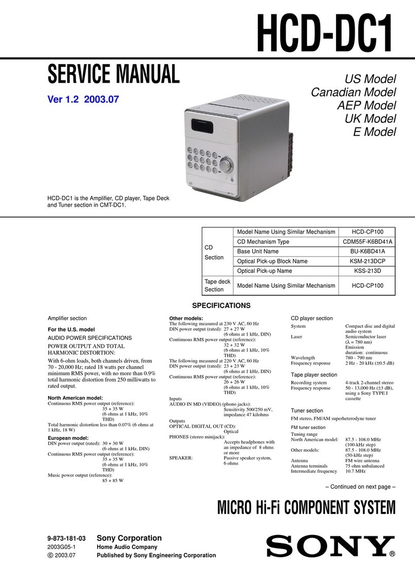
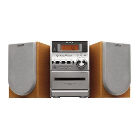
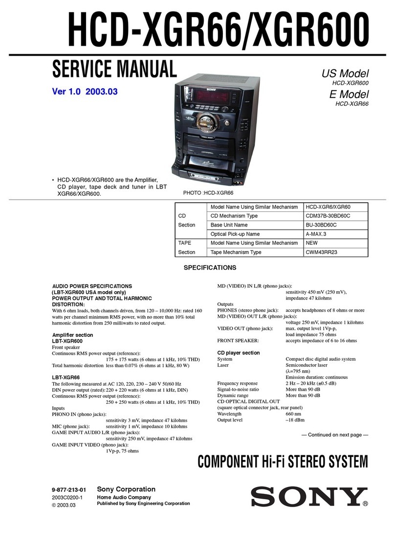
Sony HCD-MJ1 User manual

CD Model Name Using Similar Machanism HCD-D1/T1
––––––––––––––––––––––––––––––––––––––––––––––––––––––––––––––––––––––––––––––––––––––––––––––––––––––––
Section CD Mechanism Type CDM13C-5BD19
––––––––––––––––––––––––––––––––––––––––––––––––––––––––––––––––––––––––––––––––––––––––––––––––––––––––
Base Unit Name BU-5BD19
MD Model Name Using Similaar Mechanism NEW
––––––––––––––––––––––––––––––––––––––––––––––––––––––––––––––––––––––––––––––––––––––––––––––––––––––––
Section Mini Disc Mechanism Type MDM-2ER
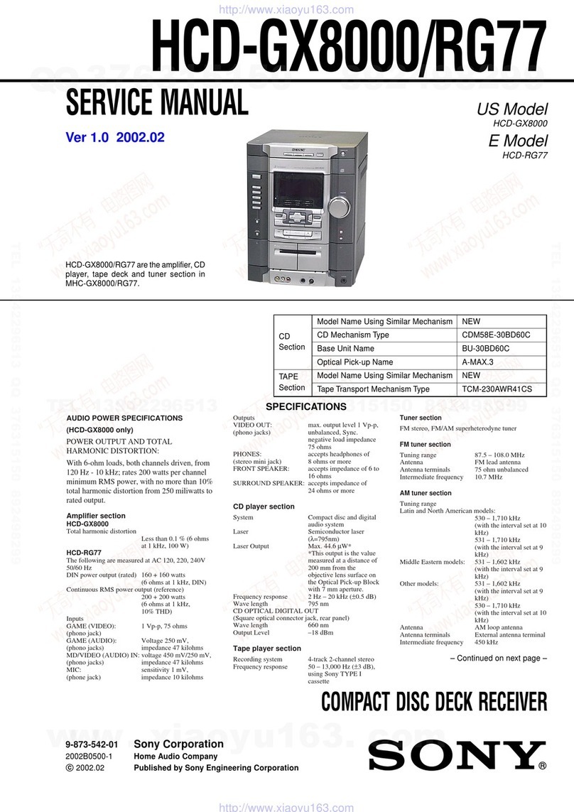
SERVICE MANUAL
FLAT COMPONENT SYSTEM
HCD-MJ1
US Model
Canadian Model
AEP Model
UK Model
E Model
SPECIFICATIONS
rHCD-MJ1 is the tuner, CD
amplifier and MDsection in
MJ-L1.
CD ptayer section
System Compact disc and digital audio system
Laser Semiconductor laser (λ=780 nm)
Emission duration: continuous
Laser output
Max 44.6 µW*
* This output is the value measured at a
distance of 200mm from the objective
lens surface on the Optical Pick-up
Block with 7 mm aperture.
Wavelength780 - 790 nm
Frequency response
2 Hz - 20 kHz
MiniDisc deck section
System MiniDisc digital audio system
Disc MiniDisc
Laser Semiconductor laser (λ= 780 nm)
Laser output
Max 44.6 µW*
* This output is the value measured at a
distance of 200mm from the objective
lens surface on the Optical Pick-up
Block with 7 mm aperture.
Laser diode properties
Materi.II: GaAIAs
Revolutions (CLV)
Approx. 400 rpm to 900 rpm
Error correction
Adv,Inced Cross IntL•rleave Rced
Solomon Code (ACIRC)
Sampling frequency
44.1 kHZ
Modulation system
EFM
(Eight-to-Fourteen Modula tion)
Number of channels
2 stereo channels
Frequency response
5 Hz - 20 kHz
Wow and fluttei
Below measurable limit
Tuner section
FM tuner section
Tuning range
US, Canadian model
: 87.5 - 108.0 MHz (100 kHz step)
Except US, Canadian model
: 87.5 - 108.0 MHz (50 kHz step)
Aerial FM Iead aerial
Aerial terminal
75 ohm unbalanced
Intermediate frequency
l0.7 MHz
AM tuner section
Tuning range
US, Canadian model
: 530 - 1.710 kHz
(with the interval set at 10 kHz)
AEP, UK, German, Italian, Singapore,
Hong kong model
: 531 - 1.602 kHz
(with the interval set at 9 kHz)
Aerial AM Ioop aerial,
External aerial terminals
Intermediate frequency
450 kHz
Timer section
System Quartz lock system
Timer setting
One-minute step
Sleep timer10-minute step. max. 90 minutes
– Continued on pag 2 –
US and foreign patents licensed from Dolby
Laboratories Licensing Corporation.
Ver 1.2 2003.12
9-960-606-13
2003L02-1
© 2003.12
Sony Corporation
Home Audio Company
Published by Sony Engineering Corporation

– 2 –
TABLE OF CONTENTS
Specifications ............................................................................... 1
1. SERVICING NOTES..................................................4
2. GENERAL
Index to parts and Controls .................................................... 5
3. DISASSEMBLY
3-1. Case (Top) Section and
Plate (T back) Ornamentel Removal............................... 8
3-2. Main board,Tuner board and Display board Removal .... 8
3-3. CD Mechanism, MD Mechanism and
Digital board Removal .................................................... 9
4. DISCTABLE GETTING OUT PROCEDURE
ONTHE POWER SUPPLY IS OFF ....................... 10
5. TEST MODE ............................................................. 11
6. ELECTRICAL ADJUSTMENTS ..................................... 14
7. EXPLANATION OF ICTERMINALS ...................... 22
8. DIAGRAMS
8-1. Block Diagram –Main Section– ................................. 30
8-2. Block Diagram –MD Section– ................................... 33
8-3. Circuit Boards Location.............................................. 37
8-4. Printed Wiring Boards –Main Section–...................... 38
8-5. Schematic Diagram –Main Section– .......................... 41
8-6. Schematic Diagram –Digital Section– ....................... 46
8-7. Printed Wiring Boards –Digital Section– ................... 51
8-8. Printed Wiring Boards –BD : MD Section– ............... 54
8-9. Schematic Diagram –BD : MD Section– ................... 57
8-10. Schematic Diagram –Display Section– ...................... 61
8-11. Printed Wiring Boards –Display Section– .................. 65
8-12. Schematic Diagram –BD : CD Section– .................... 70
8-13. Printed Wiring Boards –BD : CD Section– ................ 73
8-14. IC Block Diagram....................................................... 75
9. EXPLODED VIEWS
9-1. Cabinet Section............................................................. 79
9-2. Chassis Section-1.......................................................... 80
9-3. Chassis Section-2.......................................................... 81
9-4. MD Mechanism Section (MDM-2ER) ......................... 82
9-5. Base Unit Section (MD) (MBU-2) ............................... 83
9-6. CD Mechanism Section-1 (CMD-5BD19) ................... 84
9-7. CD Mechanism Section-1 (CMD-5BD19) ................... 85
10. ELECTRICAL PARTS LIST ............................................ 86
Amplifier section
DIN power output
30 W + 30 W
(6 ohms at 1 kHz, DIN)
Continuous RMS power output
US, Canadian model :
30 W + 30 W
(6 ohms at 40Hz-16kHz, 1.0% THD)
35 W + 35 W
(6 ohms at 1kHz, 5% THD)
POPO 350W
Except US, Canadian model :
40 W + 40 W
(6 ohms at 1 kHz, lO% THD)
Music power output
70W+70W
(6 ohms at 1 kHz. lO% THD)
Inputs TAPE (phono jacks):
voltage 250 mV
impedance 47 kilohms
Outputs TAPE (phono jacks):
voltage 250 mV
impedance 1 kilohms
PHONES (stereo phone jack):
accepts headphones of 8 ohms
or more.
Supplied accessories
Sony RM-SMJI Remote (1)
Sony lithium battery. CR2025 (1 )
FM lead aerial (1)
AM loop aerial (1)
Speaker cords (2)
General
Power requirements
Destination Power Power
requirements consumption
US, Canadian model 120V AC,60Hz 95W
AEP, UK, German 220-230V AC, 50/60Hz 95W
Italian model
E, Singapore, 110-120V/ 220-240V AC,
Hong Kong model 50/60Hz Adjustable with 95W
the Voltage Selector
Dimensions
Approx. 430 x 95 x 290 mm
(17 x 33/4x 11 1/2inches) (w/h/d)
incl. projecting parts and controls
Mass Approx. 7.0 kg (15 Ib 7 oz)
Design and specifications are subject to
change without notice.

– 3 –
MODEL NO. HCD-MJ1
MODEL IDENTIFICATION
US, Canadian model : AC120V ⁄60Hz
AEP, UK, German, Italian model
: AC220-230V ⁄50/60Hz
Hong kong, Sinagpore mdel
: AC110-120V/AC220-240V ⁄50/60Hz
FLAT COMPONENT SYSTEM
Laser component in this product is capable of emitting radiation
exceeding the limit for Class 1.
This Compact Disc player is
classified as a CLASS 1 LASER
product.
The CLASSLASER
PRODUCT label is located on
the rear exterior.
For customers in Europe
This caution la-
bel is located
insuide the unit.
CAUTION
Use of controls or adjustments or performance of procedures other
than those specified herein may result in hazardous radiation expo-
sure.
SAFETY CHECK-OUT
After correcting the original service problem, perform the follow-
ing safety check before releasing the set to the customer :
Check the antenna terminals, metal trim, “metallized” knobs,
screws, and all other exposed metal parts for AC leakage. Check
leakage as described below.
LEAKAGETEST
The AC leakage from any exposed metal part to earth ground and
from all exposed metal parts to any exposed metal part having a
return to chassis, must not exceed 0.5mA (500 microampers).
Leakage current can be measured by any one of three methods.
1. A commercial leakage tester, such as the Simpson 229 or RCA
WT-540A. Follow the manufacturers’ instructions to use these
instruments.
2. A battery-operatedAC milliammeter. The Data Precision 245
digital multimeter is suitable for this job.
3. Measuring the voltage drop across a resistor by means of a
VOM
or battery-operated AC voltmeter. The “limit” indication is
0.75V, so analog meters must have an accurate low-voltage
scale. The Simpson 250 and Sanwa SH-63Trd are examples of a
passive VOM that is suitable. Nearly all battery operated digital
multimeters that have a 2V AC range are suitable. (See Fig. A)
Earth Ground
Fig. A. Using an AC voltmeter to check AC leakage.
AC
Voltmeter
(0.75V)
0.15
µ
F1.5k
Ω
To Exposed Metal
Parts on Set
SAFETY-RELATED COMPONENTWARNING!!
COMPONENTS IDENTIFIED BY MARK !OR DOTTED LINE
WITH MARK !ONTHE SCHEMATIC DIAGRAMS AND IN THE
PARTS LIST ARE CRITICALTO SAFE OPERATION.
REPLACE THESE COMPONENTS WITH SONY PARTS WHOSE
PART NUMBERS APPEAR AS SHOWN IN THIS MANUAL OR IN
SUPPLEMENTS PUBLISHED BY SONY.
ATTENTION AU COMPOSANT AYANT RAPPORT
À LA SÉCURITÉ!
LES COMPOSANTS IDENTIFIÉS PAR UNE MARQUE !SUR LES
DIAGRAMMES SCHÉMATIQUES ET LA LISTE DES PIÈCES SONT
CRITIQUES POUR LA SÉCURITÉ DE FONCTIONNEMENT. NE
REMPLACER CES COMPOSANTS QUE PAR DES PIÈCES SONY
DONT LES NUMÉROS SONT DONNÉS DANS CE MANUEL OU
DANS LES SUPPLÉMENTS PUBLIÉS PAR SONY.

– 4 –
SECTION 1
SERVICING NOTES
NOTES ON HANDLINGTHE OPTICAL PICK-UP
BLOCK OR BASE UNIT
The laser diode in the optical pick-up block may suffer electrostatic
breakdown because of the potential difference generated by the
charged electrostatic load, etc. on clothing and the human body.
During repair, pay attention to electrostatic breakdown and also use
the procedure in the printed matter which is included in the repair
parts.
The flexible board is easily damaged and should be handled with
care.
NOTES ON LASER DIODE EMISSION CHECK
The laser beam on this model is concentrated so as to be focused on
the disc reflective surface by the objective lens in the optical pick-up
block. Therefore, when checking the laser diode emission, observe
more than 30 cm away from the objective lens.
Cautions when replacing IC121 and
IC171 on the BD board
A change has been made from CXD2535BR due to a modification of
IC121 on the BD board in this unit.
Accompanying this modification, a portion of the nonü]volatile
memory of IC171 (XC24CO1S) has been changed.
Conversely, when IC121 has been replaced, use CXD2535BR and
rewrite the contents of IC171.
Contents of non-volatile memories CXD2535BR
Address CXD2535BR
15 93
2D 1A
2E 1A
Rewrite Procedure for Non-volatile Memory
(1) With the power switched off and the power plug plugged into a
socket.press the BASS/TREBLEbutton. CLOCK button,andMD
button more than one at a time in order.
(2)Rotate the JOG dial knob and display the “EEP MODE”.
When you press theYES key, the display changes to show
“EEP**@@”.
(Here, **indicates the address, and @@ indicates the data.)
(3)Rotate the JOG dial knob and display the “EEP 15 @@”.
(4)When you press the CD SYNCHRO button, “EEP 15 @@>@@”
is displayed so then turn the JOG dial knob to show ügEEP 15
@@>93”
(5)Press the YES key and “COMPLETE” will appear for a moment
and data shown as “EEP 15 93” is being rewritten.
(6)Rewrite address 2D and address 2E, into 1A using steps (3) to (5)
above.
(7)When all changes are complete, press the NO key and display
“EEP MODE”.
(8)Press the REPEAT button. If no disc is loaded, the time is dis-
played, so unplug the power plug. If a disc is loaded, the disc is
ejected, then the time is displayed. Unplug the power plug from
the socket to end EEP rewrite mode. (See “How to end test mode”
below.)
Note: Changes in the contents of non-volatile memory are not re-
flected until the power is switched off, then on.
HOW TO END TEST MODE
Method :
l Press the REPEAT button.
2 If no disc is loaded, the time is displayed. If a disc is loaded, the
disc is ejected, then the time is displayed .
3 Unplug the power plug from the socket.
ENTERINGTEST MODE
When you press the DISP button, pbutton, and EDIT
button at the
same tilne, the system goes into key, fluorescent tube, jogr and LED
check mode.
rFluorescent tube check
All the lights light up. Then, each time you press the
ENTER
but-
ton, the display mode changes as shown below.
nAll lit npartially lit l npartially lit 2
rLED check
When you turn the jog dial, the LEDS change froln all lit to indi-
vidually lit.
rKey check
The EDIT/NO button puts the system into key/jog check mode .
When you press a button, the number is counted up.
However, pressing a button again that you already pressed does
not count up the number.
Turning the jog dial to the right increases the jog count display,
turning the jog dial to the left decreases the jog count.
When you have pressed all the buttons and “KEY= 0K” is dis-
played, pressing any button ends test Inode.

– 5 –
SECTION 2
GENERAL This section is extracted from in-
struction manual.

– 6 –

– 7 –

– 8 –
CASE (TOP) SECTION
4
+BVTT 3 x 6
1
+BVTT 3 x 10
2
+BVTP 3 x 10
1
+BVTT 3 x 10
3
PLATE (T BACK) ORNAMENTAL
8
Wire (flat type) (11CORE)
to Switch (R) BOARD
MAIN BOARD
5
+BVTP 3 x 10
5
+BVTP 3 x 10
7
6
+BVTT 3 x 10
1
+BVTP 3 x 8
5
CN102 (8pin)
to AMP BOARD (CN901)
1
+BVTP 3 x 8
4
Wire (flat type) (13CORE) (CN103)
to TERMINAL BOARD (CN602)
3
Wire (flat type) (19CORE) (CN105)
to CDM
!§
+BVTP 3 x 8
!¶
Wire (flat type) (15CORE) (CN4)
to MAIN BOARD (CN104)
TUNER BOARD
!¡
CN701(4pin)
SWTCH (LID) BOARD (CN703)
and MOTOR (LID) BOARD (CN704)
8
CN106 (8pin)
to DIGITAL BOARD (CN281)
6
CN101 (9pin)
to TRANSFORMER BOARD (CN804)
MAIN BOARD
7
CN111 (3pin) toFAN801
!•
!¢
+BVTP 3 x 8
!∞
4
Wire (flat type) (21CORE) (CN109)
to DIGITAL BOARD (CN223)
!™
CN702 (5pin) to CDM
!£
CN706 (3pin)
to SENSOR BOARD (CN706)
!¢
+BVTP 3 x 8
DISPLAY BOARD
!º
Wire (flat type) (19CORE) (CN110)
to SWITCH (R) BOARD (CN501)
9
Wire (flat type) (19CORE) (CN107)
to DISPLAY BOARD (CN551)
2
3-2. MAIN BOARD,TUNER BOARD AND DISPLAY BOARD REMOVAL
SECTION 3
DISASSEMBLY
3-1. CASE (TOP) SECTION AND PLATE (T BACK) ORNAMENTEL REMOVAL
Note : Follow the disassembly procedure in the numerical order given.

– 9 –
3-3. CD MECHANISM, MD MECHANISM AND DIGITAL BOARD REMOVAL
1
+BVTP 3 x 8
3
+BVTT 3 x 6
CHASSIS (M)
4
!£
+BVTT3 x 10
CD MECHANISM SECTION
CASE (BOTTOM) SECTION
!¢
!™
5
+BVTT3 x 6
1
+BVTP 3 x 8
!¡
+BVTT3 x 10
MD MECHANISM SECTION
SHELDE
!º
+BVTP 3 x 8
7
+BVTP 3 x 8
9
+BVTT 3 x 10
SHELDE (T)
DIGITAL BOARD
2
+BVTT3 x 10

– 10 –
DOOR
CAM
1
TWEEZERS
4
2
3
SECTION 4
DISCTABLE GETTING OUT PROCEDURE ONTHE POWER SUPPLY IS OFF
DISC TABLE

– 11 –
5-1. How to enter theTest Mode
With the power switched off and the power plug plugged into a socket, press the BASS/TREBLE button, CLOCK button, and MD button more
than one at a time in order.
5-2. How to Release theTest Mode
Press the REPEAT button.
5-3. Basic Operations of theTest Mode
All operations are performed using the JOG dial (Rotary Encoder) ,YES (ENTR/TES)button, and NO (EDIT/ON)button.
The functions of these keys are as follows.
Function Contents
JOG dial Changes parameters and modes.
YES button Proceeds onto the next setp. inalizes input
NO button Returns to previous step. Stops operations.
5-4. Selecting theTest Mode
Eight test modes are selected by turning the AMS knob.
Display Contents
TEMP ADJUST Temperature compnsation offset adjustment
LDPWR ADJUST Laser power adjustment
EFBAL ADJUST Traverse adjustment
FBIAS ADJUST Focus bias adjustment
FBIAS CHECK Focus bias check
CPLAY MODE Continuous playback mode
CREC MODE Continuous recording mode
EEP MODE Non-volatile memory mode*
For detailed description of each adjustment mode, refer to 6. ElectricalAdjustments.
If a different adjustment mode has been selected by mistake, press the NO button to exit from it.
* The EEP MODE is not used in servicing. If set accidentally, press the NO button immediately to exit it.
5-5-1. Operating the Continuous Playback Mode
1. Entering the continuous playback mode
1Set the disc in the unit (either MO or CD).
2Rotate the JOG dial and display “CPLAY MODE”.
3Press theYES button to change the display “CPLAY IN”.
4When access completes, the display changes to “C1 = AD = ”
Note : The “ ” displayed are arbitrary numbers.
2. Changing the parts to be played back
1Press theYES button during continuous playback to change the display to “CPLAY MID”, “CPLAY OUT”.
When pressed another time, the parts to be playedback can be changed.
2When access completes, the display changes to “C1 = AD = ”
Note : The “ ” displayed are arbitrary numbers.
3. Ending the continuous playback mode
1Press the No button. The display will change to “CPLAY MODE”.
2Press the MD §button and remove the disc.
Note 1 : The playback start addresses for IN, MID, and OUT are as follows.
Press the DISPIAY button twice to display thae address. Pressing the DISPIAY buttan again returns the display to
“C1 = AD = ”
IN 40h cluster
MID 300h cluster
OUT 700h cluster
SECTION 5
TEST MODE

– 12 –
5-5-2. Operating the Continuous Recording Mode
1. Entering the continuous recording mode
1Set the MO disc in the unit.
2Rotate the JOG dial knob and display “CREC MODE”.
3Press theYES button to change the display to “CREC IN”.
4When access completes, the display changes to “CREC ( ) and REC lights up.
Note : The “ ” displayed are arbitrary numbers.
2. Changing the parts to be recorded
1When theYES button is pressed during continuous recording. the display changes to “CREC MID”, “CREC OUT”and REC goes off.
When pressed another time, the parts to be recorded can be changed.
2When access completes, the display changes to “CREC ( ) and REC lights up.
Note : The “ ” displayed are arbitrary numbers.
3. Ending the continuous recording mode
1Press the No bottan. The display change to CREC MODE” and REC goes off.
2Press the MD §button and remove the disc.
Note 1 : The recording start addresses for IN, MID, and OUT are as follows.
IN 40h cluster
MID 300h cluster
OUT 700h cluster
Note 2 : The No buttton can be used to stop recording anytime.
Note 3 : During the test mode, the erasing-protection tab will not be detected. Therefore be careful not to set the continuous recording mode
when a disc not be erased is set in the unit.
Note 4 : Do not perform continuous recording for long periods of time above 5minutes.
Note 5 : During continuous recording, be careful not to apply vibration.
5-5-3. Non-Volatile Memory Mode (EEP MODE)
This mode reads and writes the contents of the nonü]volatile memory.
It is not used in servicing. If set accidentally, press the No button immediately to exit it.
5-6. Functions of Other buttons
Function Contents
^Sets continuous playback when pressed in the STOP state.
When pressed during continuouse playback,the tracking servo turns ON/OFF.
pStops continuouse playback and continuouse recording.
)The sled moves to the outer circumference only when this is pressed.
0The sled moves to the inner circumference only when this is pressed.
rTurns recording ON/OFF when presed during continuoos playback.
SCROOLL Switches butween the pit and groove modes when pressed.
DISPLAY Switches the display whin pressed. Returns to previous step. Stops operations.
Note : The erasing-protection tab is not detected during the test mode. Recording will start regardless of the position of the erasing-protection
tab when the r(REC) button is pressed.

– 13 –
5-7.Test Mode Displays
Each time the DISPLAY button is pressed, the display changes in the following order.
MODE displaynError rate displaynAddress display
1. MODE display
Displays “TEMP ADJUST” , “CPLAY MODE” , etc.
2. Address display
Addresses are displayed as follows.
h = s = (MO pit and CD)
h = a = (MO groove)
h = Header address
s = SUBQ address
a = ADIP address
* A ‘ ’ display appears when the address cannot be loaded.
3. Error rate display
Error rates are displayed as follows.
C1 = AD =
C1 = Indicates C1 error
AD = Indicates ADER
5-8. Meanings of Other Displays
Display Contents
Light Off Blinkig
(During continuous playbak STOP
^Tracking servo OFF Tracking servo ON
REC Recording mode ON Recording mode OFF
SYNC CLV LOCK CLV UNLOCK
TRACK Pit Groove
DISC High refiection Low refiection
LEVEL-SYNC CLV-S CLV-A
MEMORY ABCD adjustment completed
SHUFFLE Focus auto gain successful Focus auto gain successful
Tracking auto gain successful Tracking auto gain failed
5-9. Precautions for Use ofTest Mode
2As loading related operations will be performed regardless of the test mode operations being performed, be sure to check that the disc
is stopped before setting and removing it.
Even if the MD §button is pressed while the disc is rotating during continuous playback, continuous recording, etc., the disc will not
stop rotating.
Therefore, it will be ejected while rotating.
* Always press the NO button before pressing the MD §button.
2The erasing-protection tab is not detected in the test mode. Therefore, when modes which output the recording laser power such as
continuous recording mode and traverse adjustment mode, etc. are set, the recorded contents will be erased regardless of the position
of the tab. When using a disc that is not to be erased in the test mode, be careful not enter the continuous recording mode and traverse
adjustment mode.

– 14 –
PRECAUTION
6-1. Precautions for Checking Laser Diode Emission
To check the emission of the leaser diode during adjustments, never
view directly from the top as this may lose your eye-sight.
6-2. Precautions for Use of optical pickup (KMS-210A)
As the laser diode in the optical pickup is easily damaged by static
electricity, solder the laser tap of the flexible board when using it.
Before disconnecting the connector, desolder first. Before connect-
ing the connector,be careful not to remove the solder. Also tale ad-
equate measures to prevent damage by static electricity. Handle the
flexible board with care as it breaks easily.
Laser tap
Optical pickup flexible board
6-3. Precautions for Adjustments
1) when replacing the following parts, perform the adjustments and
checks with O in the order shown in the following table.
Optical BD (MD) BOARD
pickup IC171 D101 IC101,IC121,IC191
1. Temperature
compensation X O O O
offset adjustment
2. Laser power OXX O
adjustment
3. Traverse OOX O
adjustment
4. Focus bias OOX O
adjustment
5. Error rate check O O X O
2) Set the test mode when performing adjustments.
After completing the adjustments,exit the test mode.
3) Perform the adjustments in the order shown.
4) Use the following tools and measuring devices.
rTest disc (CD) TDYS-1 (Parts No. 4-963-646-01)
rLaser power meter LPM-8001 (Parts No. J-2501-046-A)
rOscilloscope
rDigital voltmeter
rThermometer
5) When observing several signals on the oscilloscope, etc., make
sure that VC and GND do not connect inside the oscilloscope.
(VC and GND will become short-circuited)
6) Do not move RV105 of the BD (MD) board. When replacing it,
adjust to the mechanical center of the semi-fixed resistor.
6-4. Creating MO Continuously Recorded Disc
* This disc is used in focus bias adjustment and error rate check.
The following describes how to create a MO continuous record-
ing disc.
1. Insert a MO disc (blank disc) commercially available.
2. Rotate the JOG dial and display “ CREC MODE”.
3. Press the YES button and display “ CREC IN”.
4. Press the YES button again to display “ CREC MID”.
“ CREC (0300)” is displayed for a moment and recording starts.
5. Complete recording within 5 minutes.
6. Press the NO button and stop recording
7. Press the MD §button and remove the MO disc.
The above has been how to create a continuous recording data for the
focus bias adjustment and error rate check.
Note :
rBe careful not to apply vibration during continuous recording.
SECTION 6
ELECTRICAL ADJUSTMENTS

– 15 –
4-6. Laser Power Adjustment
Connection :
laser power mete
r
Optical pickup
objective lens
+
–
digital voltmete
r
BD (MD) board
TP (I+5V)
TP (IOP)
Adjusting Method :
1. Set the laser powermeterontheobjective lens of theopticalpickup.
(When it cannot be set properly, press the 0button or )but-
ton and move the optical pickup.)
Connect the digital volt meter to TP (IOP) and TP (I+5V).
2. Rotate the JOG dial and display “LDPWR ADJUST”.
(Laser power : For adjustment)
3. Press theYES button twice and display “LD $ 4B = 3.5mW”.
4. Adjust RV102 of the BD (MD) board so that the reading of the
+0.1
laser power meter becomes 3.4 - 0 mW.
5. Press theYES button and display “LD $ 96 = 7.0mW”.
(Laser power : MO writing)
6. Check that the laser power meter and digital voltmeter readings
satisfy the specified value.
Specification :
KMS210A
27X40
B0825
IOP = 82.5mA in this case
IOP (mA) = Digital voltmeter reading (mV) / 1(Ω)
Laser power meter reading : 7.0 ±0.3 mW
Digital voltmeter reading : Optical pickup displayed value
±10%
(Optical pickup label)
7. Press theYES button and display “LD $ 0F = 0.7mW”.
(Laser power : MO reading)
8. Check that the laser power meter at this time satisfies the speci-
fied value.
Specification :
Laser power meter reading : 0.70 ± 0.1mW
9. Press the NO button and display “LDPWR ADJUST”, and stop
laser emission.
(The NO button is effective at all times to stop the laser emis-
sion.)
6-5.Temperature Compensation Offset Adjustment
Save the temperature data at that time in the non-volatile memory as
25°C reference data.
Note :
1. Usually, do not perform this adjustment.
2. Perform this adjustment in an ambient temperature of 22°C to
28°C. Perform it immediately after the power is turned on when
the internal temperature of the unit is the same as the ambient
temperature
3. When D101 has been replaced, perform this adjustment after the
temperature of this part has become the ambient temperature.
Adjusting Method :
1. Rotate the JOG dial and display “TEMP ADJUST”.
2. Press the YES button and select the “TEMP ADJUST” mode.
3. “TEMP = ”and the current temperature data will be displayed
4. To save the data, press theYES button.
When not saving the data, press the NO button.
5. When the YES button is pressed, “TEMP = SAVE”will be
displayed for some time, followed by “TEMPADJUST”.
When the NO button is pressed, “TEMP ADJUST” will be dis-
played.
Specifications :
The temperature should be within “TEMP = EO” to “TEMP = IF”.

– 16 –
6-7.Traverse Adjustment
Connection :
+
–
BD (MD) board
TP (TEO)
TP (VC)
oscilloscope
Adjusting Method :
1. Connect an oscilloscope to TP (TEO) and TP (VC) of the BD
(MD) board.
2. Load a MO disc (any available on the market).
3. Press the 0button or )button and move the optical pickup
outside the pit.
4. Rotate the JOG dial and display “EFBAL ADJUST”.
5. Press theYES button and display “EFBAL MO-W”.
(Laser powerWRITE power/Focus servo ON/tracking servo OFF/
spindle (S) servo ON)
6. Adjust RV101 of the BD (MD) board so that the waveform of the
oscilloscope becomes the specified value.
(MO groove write power traverse adjustment)
VC
A
B
(Traverse Wavefom)
Specification : A = B
7. Press theYES button and display “EFB = $ MO-R”.
(Laser power : MO reading)
8. Rotate the JOG dial so that waveforms of the oscilloscope be-
comes the specified value.
(When the JOG dial is rotated, the of “EFB = ” changes and
the waveform changes.) in this adjustment, waveform varies at
intervals of approx. 3%. Adjust the waveform so that the speci-
fied value is satisfied as much as possible.
(MO groove read power traverse adjustment)
VC
A
B
(Traverse Wavefom)
Specification : A = B
9. Press the YES button, display “EFB = $ SAVE” for a moment
and save the adjustment results in the non-volatile memory.
Next “EFBAL MO-P” is displayed.
10.Press theYES button and display “EFB = $ MO-P”.
The optical pickup moves to the pit area automatically and servo
is imposed.
11.Rotate the JOGdialuntil the waveformsof the oscilloscopemoves
closer to the specified value.
In this adjustment, waveform varies at intervals of approx. 3%.
Adjust the waveform so that the specified value is satisfied as
much as possible.
VC
A
B
(Traverse Wavefom)
Specification : A = B
12.Press the YES button, display “EFB = SAVE ” for a moment
and save the adjustment results in the non-volatile memory.
Next “EFBAL CD” is displayed. The disc stops rotating auto-
matically.
13.Press the MD §button and remove the MO disc.
14.Load the test disc TDYS-1.
15.Press the YES button and display “EFB = CD ” . Servo is im-
posed automatically.
16.Rotate the JOG dial so that the waveforms of the oscilloscope
moves closer to the specified value.
In this adjustment, waveform varies at intervals of approx. 3%.
Adjust the waveform so that the specified value is satisfied as
much as possible.
VC
A
B
(Traverse Wavefom)
Specification : A = B
17.Press the YES button, display “EFB = $ SAVE” for a moment
and save the adjustment results in the non-volatile memory.
Next “EFBAL ADJUST” is displayed.
18.Press the MD §button and remove the test disc TDYS-1.
Note 1) Data will be erased during MO reading if a recorded disc is
used in this adjustment.
Note 2) If the traverse waveform is not clear, connect the oscillo-
scope as shown in the following figure so that it can be seen
more clearly.
+
–
TP (TEO)
TP (VC)
oscilloscope
10pF
330k
Ω

– 17 –
6-8. Focus Bias Adjustment
Adjusting Method :
1. Load a continuously recorded disc (Refer to “6-4. Creating MO
Continuously Recorded Disc”.)
2. Rotate the JOG dial and display “CPLAY MODE”.
3. Press the YES button twice and display “CPLAY MID”.
4. Press the NO button when “C1 = AD = ” is displayed.
5. Rotate the JOG dial and display “FBIAS ADJUST”.
6. Press theYES button and display “ / a = ”.
The first four digits indicate the C1 error rate, the two digits after
[/] indicate ADER, and the 2 digits after [a =] indicate the focus
bias value.
7. Rotate the JOG dial in the clockwise direction and find the focus
bias value at which the C1 error rate becomes 220.
8. Press theYES button and display “ / b = ”.
9. Rotate the JOG dial in the counterclockwise direction and find
the focus bias value at which the C1 error rate becomes 220.
10.Press theYES button and display “ / c = ”.
11.Check that the C1 error rate is below 50 and ADER is 00.
Then press theYES button.
12.If the “( )” in “ - - ( )” is above 20, press theYES
button.
If below 20, press the NO button and repeat the adjustment from
step 2 again.
13.Press the NO button and press the MD §button to remove the
continuously recorded disc.
Note 1 :The relation between the C1 error and focus bias is as shown
in the following figure. Find points a and b in the following
figure using the above adjustment. The focal point position
c is automatically calculated from points a and b.
Note 2 :As the C1 error rate changes, perform the adjustment using
the average vale.
C1 error
220
Focus bias value
(F, BIAS)
bc b
6-9. Error Rate Check
6-9-1. CD Error Rate Check
Checking Method :
1. Load a test disc TDYS-1.
2. Rotate the JOG dial and display “CPLAY MODE”.
3. Press the YES button twice and display “CPLAY MID”.
4. “C1 = AD = - -” is displayed.
5. Check that the C1 error is below 20.
6. Press the NO button, stop playback, press the MD §button, and
remove the test disc.
6-9-2. MO Error Rate Check
Checking Method :
1. Load a continuously recorded disc (Refer to “6-4. Creating MO
Continuously Recorded Disc”.)
2. Rotate the JOG dial and display “CPLAY MODE”.
3. Press the YES button twice and display “CPLAY MID”.
4. “C1 = AD = ”is displayed
5. If the C1 error rate is below 50, check that ADER is 00.
6. Press the NO button, stop playback, press the MD §button, and
remove the continuously recorded disc.
6-10. Focus Bias Check
Change the focus bias and check the focus tolerance amount.
Checking Method :
1. Load a continuously recorded disc (Refer to “6-4. Creating MO
Continuously Recorded Disc”.)
2. Rotate the JOG dial and display “CPLAY MODE”.
3. Press the YES button twice and display “CPLAY MID”.
4. Press the NO button when “C1 = AD = ” is displayed
5. Rotate the JOG dial and display “FBIAS CHECK”.
6. Press theYES button and display “ / c = ”.
The first four digits indicate the C1 error rate, the two digits after
[/] indicate ADER, and the 2 digits after [c =] indicate the focus
bias value.
Check that the C1 error is below 50 and ADER is 00.
7. Press theYES button and display “ / b = ”.
Check that the C1 error is not below 220 and ADER is not above
00 every time.
8. Press theYES button and display “ / a = ”.
Check that the C1 error is not below 220 and ADER is not above
00 every time.
9. Press the NO button, next press the MD §button, and remove the
continuously recorded disc.
Note 1 : If the C1 error andADER are above 00 at points a or b, the
focus bias adjustment may not have been carried out prop-
erly. Adjust perform the beginning again.

– 18 –
6-11. Adjusting Points and Connecting Points
[BD (MD) BOARD] (Component side)
IC191
D101
[BD (MD) BOARD] (Conductor side)
(IOP)
(I+5V)
RV101
RV102
(VC) IC101
(TEO)
IC121

– 19 –
FM Stereo Separation Adjustment
Setting :
FM RF SSG FM ANTENNA terminal (TM1)
set
Carrier frequency : 98MHz
Output level : 1mV (60dB)
Modulation
Main (1kHz) : 33.75kHz dev. (45%)
Sub (1kHz) : 33.75kHz dev. (45%)
Pilot (19kHz) : 7.5kHz dev. (10%)
+
–
J601 (LINE OUT)
47k
Ω
level mete
r
Procedure :
Turn the set to 98MHz.
FM stereo VTVM VTVM
signal generator connection reading (dB)
output channel
L-CH L-CH A
R-CH L-CH
B
Adjust RV (FM STEREO
SEPARATION ADJUST-
MENT) for minimum read-
ing.
R-CH R-CH C
L-CH R-CH
D
Adjust RV (FM STEREO
SEPARATION ADJUST-
MENT) for minimum read-
ing.
L-CH Stereo separation : A- B
R-CH Stereo separation : C- D
The separations of both channels should be equal.
Adjustment Location : TB1 (TUNER board)
[TB1TUNER BOARD] (Conductor side )
RV (FM TUNED
LEVEL ADJUSTMENT
)
RV (AM TUNED LEVEL ADJUSTMENT)
RV (FM STEREO SEPARATION ADJUSTMENT)
IC
IC
TUNER SECTION
As a front-end (TB1) is difficult to repair if faulty, replace it with
new one.
But AEP, UK, German, and Italian model are please note, however,
that the following adjustments are possible:
AM Section Adjustment
AMTuned Indication Lighting Level Adjustment
Band : AM
Setting :
60 cm
AM ANTENNA
terminal (TM1)
set
AM RF SSG
carrier frequency : 999kHz
Modulation : 400Hz 30%
loop antenna loop antenna of
accessories
Procedure :
1. Set AM RF SSG output level to 81dBµ so that the input level
becomes 55dBµ.
2. Tune the set to 999kHz .
3. Adjust RV(AM TUNED LEVEL ADJUSTMENT) so that the
TUNED light up.
Adjustment Location : TB1 (TUNER board)
FM Section Adjustment
FMTuned Indication Lighting Level Adjustment
Band : FW
Setting :
FM RF SSG FM ANTENNA terminal (TM1)
set
carrier frequency : 98MHz
Modulation : 1kHz,75kHz deviation
Procedure :
1. Supply a 17.8 µV (25dBµ) 98MHz signal to the ANTENNA ter-
minal.
2. Tune the set to 98MHz.
3. Adjust RV(FM TUNED LEVEL ADJUSTMENT) so that the
TUNED light up.
Adjustment Location : TB1 (TUNER board)

– 20 –
CD SECTION
NOTE :
1. CD Block basically constructed to operate without adjustment.
Therefore, check each item in order given.
2. UseYEDS-18 disc (3-702-101-01) unless otherwise indicated.
3. Use the oscilloscope with more than 10MΩimpedance.
4. Clean an object lens by an applicator with neutral detergent when
the signal level is low than specified value with the following
checks.
Focus Bias Adjustment
This adjustment is to be done when the optical block is replaced.
Adjustment procedure :
+
–
BD (CD) board
TP (RF)
TP (VC)
oscilloscope
(DC range)
1. Connect oscilloscope to test point TP (VC) and TP (RF) on BD
(CD) board.
2. Connect TPADJ (IC301 @• pin) to ground with lead wire on Main
board.
3. Turned power switch ON. (Stop mode)
4. Put disc (YEDS-18) in and press the ^button.
5. Press the ^button (Tracking servo ON).
6. Adjust RV101 so that the oscilloscope waveform is as shown in
the figure below (eye pattern).
A good eye pattern means that the diamond shape ( ) in the center
of the waveform can be clearly distinguished.
7. After adjustment,remove the lead wire connected in step 2.
rRF signal reference waveform (eye pattern)
VOLT/DIV : 0.2V
TIME/DIV : 500n
s
1.3
±
0.3Vp-p
When observing the eye pattern, set the oscilloscope forAC range
and raise vertical sensitivity.
Adjustment Location : BD (CD) board. (see page 13)
S-Curve Check
+
–
oscilloscope
TP (FEO)
BD (CD) board
TP (VC)
Procedure :
1. Connect oscilloscope to test point TP (VC) and TP (FEO) on BD
(CD) board.
2. Connect between test point TP (FOK) and GND by lead wire.
3. Turned Power switch on.
4. Put disc (YEDS-18) in and turned Power switch on again and
actuate the focus search. (actuate the focus search when disc table
is moving in and out.)
5. Check the oscilloscope waveform (S-curve) is symmetrical be-
tween A and B. And confirm peak to peak level within
2.4 ± 0.7Vp-p.
symmetry
within 2.4
±
0.7Vp-p
A
B
S-curve waveform
6. After check, remove the lead wire connected in step 2.
Note : rTry to measure several times to make sure that the ratio
of A : B or B : A is more than 10 : 7.
rTake sweep timeaslong as possibleandlightup the bright
ness to obtain best waveform.
Adjustment Location : BD (CD) board. (see page 13)
RF Level Check
+
–
oscilloscope
TP (RF)
BD (CD) board
TP (VC)
Procedure :
1. Connect oscilloscope to test point TP (VC) and TP (RF) on BD
(CD) board.
2. Turned Power switch on.
3. Put disc (YEDS-18) in and press the ^button.
4. Confirm that oscilloscope waveform is clear and check RF signal
level is correct or not.
Note :
Clear RF signal waveform means that the shape “◊” can be clearly
distinguished at the center of the waveform.
rRF signal waveform
VOLT/DIV : 200mV
TIME/DIV : 500ns
level : 1.3
±
0.3Vp-p
Adjustment Location : BD (CD) board. (see page 13)
Table of contents
Other Sony Stereo System manuals

Sony
Sony CX-JV77 User manual

Sony
Sony GTK-XB60 User manual

Sony
Sony HCD-D170 User manual

Sony
Sony HCD-GSX75 - System Components User manual

Sony
Sony HCD-VX99 User manual

Sony
Sony CMT-M100MD User manual

Sony
Sony HCD-VX3A User manual

Sony
Sony MHC-W555 User manual

Sony
Sony CMT-M333NT User manual

Sony
Sony ZS-SAT1 User manual