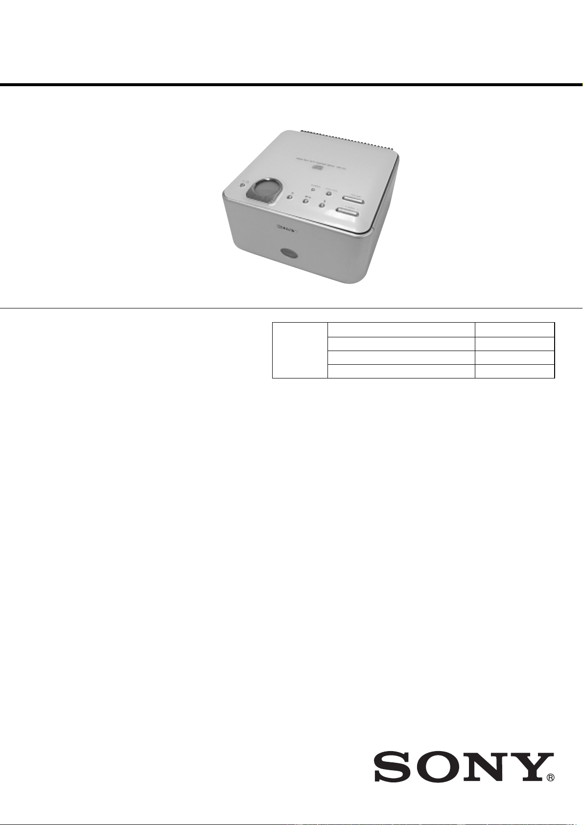
Sony SS-CCQ1 User manual

CMT-CQ1
US Model
Canadian Model
AEP Model
UK Model
E Model
Australian Model
SERVICE MANUAL
MICRO HI-FI COMPONENT SYSTEM
Sony Corporation
Home Audio Company
Published by Sony Engineering Corporation
9-877-322-01
2003E1600-1
© 2003.05
•CMT-CQ1 is composed of following models.
As for the service manual, it is issued for each component
model, then, please refer to them.
SPECIFICATIONS
Ver 1.0 2003. 05
COMPONENT MODEL NAME
COMPACT DISK DECK
RECEIVER SYSTEM
SPEAKER SYSTEM
PARTS LIST
CMT-CQ1
HCD-CQ1
SS-CCQ1
Part No. Description Remark
ACCESSORIES
************
1-477-884-11 COMMANDER, STANDARD (RM-SCQ1)(FOR WHITE)
1-477-884-21 COMMANDER, STANDARD (RM-SCQ1)(FOR BLACK)
1-501-374-72 ANTENNA, LOOP (AM)
01-770-019-11 ADAPTER CONVERSION 3P(UK,HK)
1-793-184-22 CONNECTOR (F TYPE ADAPTOR)(FM)
4-228-952-11 COVER, BATTERY (FOR RM-SCQ1)(FOR WHITE)
4-228-952-21 COVER, BATTERY (FOR RM-SCQ1)(FOR BLACK)
4-244-819-11 MANUAL, INSTRUCTION (ENGLISH)
(US,CND,AEP,UK,HK,SP,TW,AUS)
4-244-819-21 MANUAL, INSTRUCTION (FRENCH)(US,CND)
4-244-819-31 MANUAL, INSTRUCTION (FRENCH,SPANISH)(AEP,SP,MX)
4-244-819-41 MANUAL, INSTRUCTION
(GERMAN,DUTCH,ITALIAN,SWEDISH,POLISH)(AEP)
4-244-819-51 MANUAL, INSTRUCTION (TRADITIONAL CHINESE)
(HK,SP,TW)
4-244-819-61 MANUAL, INSTRUCTION (KOREAN)(KR)
The components identified by
mark 0or dotted line with mark
0are critical for safety.
Replace only with part number
specified.
Les composants identifiés par
une marque 0sont critiques
pour la sécurité.
Ne les remplacer que par une
pièceportantlenumérospécifié.
General
Power requirements
North American model: 120 V AC, 60 Hz
European model: 230 V AC, 50/60 Hz
Australian model: 230 V AC,50/60 Hz
Mexican model: 120 V AC, 60 Hz
Korean model: 220 V AC, 60 Hz
Taiwan model: 120 V AC, 50/60 Hz
Other models: 230 V AC, 50/60 Hz
Power consumption
North American and Mexican models:
40 watts
European model: 40 watts
0.35 watts (in the standby
mode)
Other models: 40 watts
Dimensions (w/h/d) Approx. 190 ×120 ×235
mm incl. projecting parts
and controls
Mass Approx. 3.5 kg
Supplied accessories Remote (1)
R6 (size AA) batteries (2)
AM loop antenna (1)
FM lead antenna (1)
Design and specifications are subject to change
without notice.
Hong Kong model: 220 V AC, 50/60 Hz
MX : Mexican model.
SP : Singapore model.
TW : Taiwan model.
•Abbreviation
AUS : Australian model.
CND : Canadian model.
HK : Hong Kong model.
KR : Korean model.

HCD-CQ1
US Model
Canadian Model
AEP Model
UK Model
E Model
Australian Model
SERVICE MANUAL
MICRO Hi-Fi COMPONENT SYSTEM
Sony Corporation
Personal Audio Company
Published by Sony Engineering Corporation
9-877-323-04
2005A16-1
© 2005.01
Ver. 1.3 2005.01
SPECIFICATIONS
This set is the tuner, CD and amplifier
section in CMT-CQ1.
Model Name Using Similar Mechanism NEW
CD Mechanism Type CDM76-K6BD44S
Base Unit Type BU-K6BD44S
Optical Pick-up Type KSS-213D/Q-RP
— Continued on next page —
Main unit
Amplifier section
AUDIO POWER SPECIFICATIONS:
(U.S.A. model only)
POWER OUTPUT AND TOTAL HARMONIC
DISTORTION:
With 6-ohm loads, both channels driven, from 120 -
10,000 Hz; rated 10 watts per channel minimum RMS
power, with no more than 10%total harmonic
distortion from 250 milliwatts to rated output.
North American model:
Continuous RMS power output (reference):
10 + 10 W
(6 ohms at 1 kHz, 10%
THD)
European and Australian models:
DIN power output (rated): 8 + 8 W
(6 ohms at 1 kHz, DIN)
Continuous RMS power output (reference):
10 + 10 W
(6 ohms at 1 kHz, 10%
THD)
Music power output (reference):
20 + 20 W
Other models:
The following measured at AC 220 V, 50/60 Hz
DIN power output (rated): 8 + 8 W
(6 ohms at 1 kHz, DIN)
Continuous RMS power output (reference):
10 + 10 W
(6 ohms at 1 kHz, 10%
THD)
The following measured at AC 240 V, 50/60 Hz
DIN power output (rated): 8 + 8 W
(6 ohms at 1 kHz, DIN)
Continuous RMS power output (reference):
10 + 10 W
(6 ohms at 1 kHz, 10%
THD)
Inputs
PC/MD/TAPE IN (stereo minijack):
Sensitivity 1.3 (MD)/
820mV (PC/TAPE)
impedance 47 kilohms
Outputs
PC/MD/TAPE OUT (stereo minijack):
Sensitivity 250 mV,
impedance 1 kilohm
PHONES (stereo minijack):
Accepts headphones with
an impedance of 8ohms or
more
SPEAKER: Accepts impedance of 6 to
16 ohms.
CD player section
System Compact disc and digital
audio system
LaserSemiconductor laser
(
λ
=780 nm)
Emission duration:
continuous
Frequency response 2 Hz – 20 kHz
Tuner section
FM stereo, FM/AM superheterodyne tuner
FM tuner section
Tuning range
North American model: 87.5 – 108.0 MHz (100-
kHz step)
Other models: 87.5 – 108.0MHz(50-kHz
step)
Antenna FM lead antenna
Antenna terminals 75 ohms unbalanced
Intermediate frequency 10.7 MHz
AM tuner section
Tuning range
Pan-American model: 530 – 1,710 kHz
(with the tuning interval
set at 10 kHz)
531 – 1,710 kHz
(with the tuning interval
set at 9 kHz)
European model: 531 – 1,602 kHz
(with the tuning interval
set at 9 kHz)
Other models: 530 – 1,710 kHz
(with the tuning interval
set at 10 kHz)
531 – 1,602 kHz
(with the tuning interval
set at 9 kHz)
Antenna AMloop antenna, external
antenna terminal
Intermediate frequency 450 kHz
CD
SECTION

2
HCD-CQ1
After correcting the original service problem, perform the
following safety checks before releasing the set to the customer:
Check theantenna terminals, metal trim, “metallized”knobs,screws,
and all other exposed metal parts forAC leakage. Check leakage as
described below.
LEAKAGE
TheAC leakage from any exposed metal part to earth ground and
from all exposed metal parts to any exposed metal part having a
return to chassis, must not exceed 0.5 mA (500 microamperes).
Leakage current can be measured by any one of three methods.
1. A commercial leakage tester, such as the Simpson 229 or RCA
WT-540A. Follow the manufacturers’instructions to use these
instruments.
2. A battery-operatedAC milliammeter. The Data Precision 245
digital multimeter is suitable for this job.
3. Measuring the voltage drop across a resistor by means of a
VOM or battery-operatedAC voltmeter. The “limit” indication
is 0.75 V, so analog meters must have an accurate low-voltage
scale. The Simpson 250 and Sanwa SH-63Trd are examples of
a passive VOM that is suitable. Nearly all battery operated
digital multimeters that have a 2V AC range are suitable. (See
Fig. A)
SAFETY CHECK-OUT
To Exposed Metal
Parts on Set
0.15 µF1.5 kΩ
AC
Voltmeter
(0.75V)
Earth Ground
Fig.A. Using an AC voltmeter to check AC leakage.
General
Power requirements
North American model: 120 V AC, 60 Hz
European model: 230 V AC, 50/60 Hz
Australian model: 230
@
30
V AC, 50/60 Hz
Mexican model: 120 V AC, 60 Hz
Korean model: 220 V AC, 60 Hz
Taiwanese model: 120 V AC, 50/60 Hz
Other models: 2 V AC, 50/60 Hz
Power consumption
North American and Mexican models:
40 watts
European model: 40 watts
0.25 watts (in the standby
mode)
Other models: 40 watts
Dimensions (w/h/d) Approx. 190 ×120 ×235
mm incl. projecting parts
and controls
Mass Approx. 3.5 kg
Design and specifications are subject to change
without notice.
Ver 1.1 2003.06

3
HCD-CQ1
TABLE OF CONTENTS
1. SERVICING NOTES ······················································· 4
2. GENERAL ·········································································· 6
3. DISASSEMBLY
3-1. Panel (Back)···································································· 9
3-2. Panel (Top) Assy ···························································10
3-3. PANEL Board ······························································· 11
3-4. CD Mechanism Deck (CDM76-K6BD44S) ················· 11
3-5. JACK Board, REG Board ············································· 12
3-6. Bearing Assy, Bushing (Guide A) ································· 12
3-7. Tuner (FM/AM) ···························································· 13
3-8. POWER Board ······························································ 13
3-9. REMOCON Board, Panel (Front) Assy························ 14
3-10. CONTROL Board ······················································· 14
3-11. Optical Pick-Up (KSM-213DCP/Z-NP) ····················· 15
3-12. BD Board ···································································· 15
3-13. KSS-213D/Q-RP························································· 16
3-14. Slider (R), Slider (L) ··················································· 16
3-15. Tray ············································································· 17
3-16. LOADING Board, Gear (P), Gear (M) ······················· 17
4. TEST MODE···································································· 18
5. ELECTRICAL ADJUSTMENTS ······························· 20
6. DIAGRAMS
6-1. Note for Printed Wiring Boards and
Schematic Diagrams ···················································· 21
6-2. Block Diagram – CD Section – ··································· 22
6-3. Block Diagram – MAIN Section – ······························ 23
6-4. Printed Wiring Board – BD Section – ························· 24
6-5. Schematic Diagram – BD Section – ···························· 25
6-6. Printed Wiring Board
– PANEL Section (Component Side) – ······················· 26
6-7. Printed Wiring Board
– PANEL Section (Conductor Side) –························· 27
6-8. Printed Wiring Board
– CONTROL Section (Component Side) –················· 28
6-9. Printed Wiring Board
– CONTROL Section (Conductor Side) –··················· 29
6-10.Schematic Diagram – CONTROL Section –··············· 30
6-11.Printed Wiring Board
– POWER Section (Component Side) –······················ 31
6-12.Printed Wiring Board
– POWER Section (Conductor Side) – ······················· 32
6-13.Schematic Diagram – POWER Section – ··················· 33
6-14.IC Block Diagrams ······················································ 34
6-15.IC Pin Function Description········································ 35
7. EXPLODEDVIEWS
7-1. Panel (Top) Section ····················································· 37
7-2. Chassis Section-1 ························································ 38
7-3. Chassis Section-2 ························································ 39
7-4. Chassis Section-3 ························································ 40
7-5. CD Mechanism Deck Section-1
(CDM76-K6BD44S) ··················································· 41
7-6. CD Mechanism Deck Section-2
(CDM76-K6BD44S) ··················································· 42
7-7. KSM-213DCP/Z-NP ··················································· 43
8. ELECTRICAL PARTS LIST······································· 44

4
HCD-CQ1
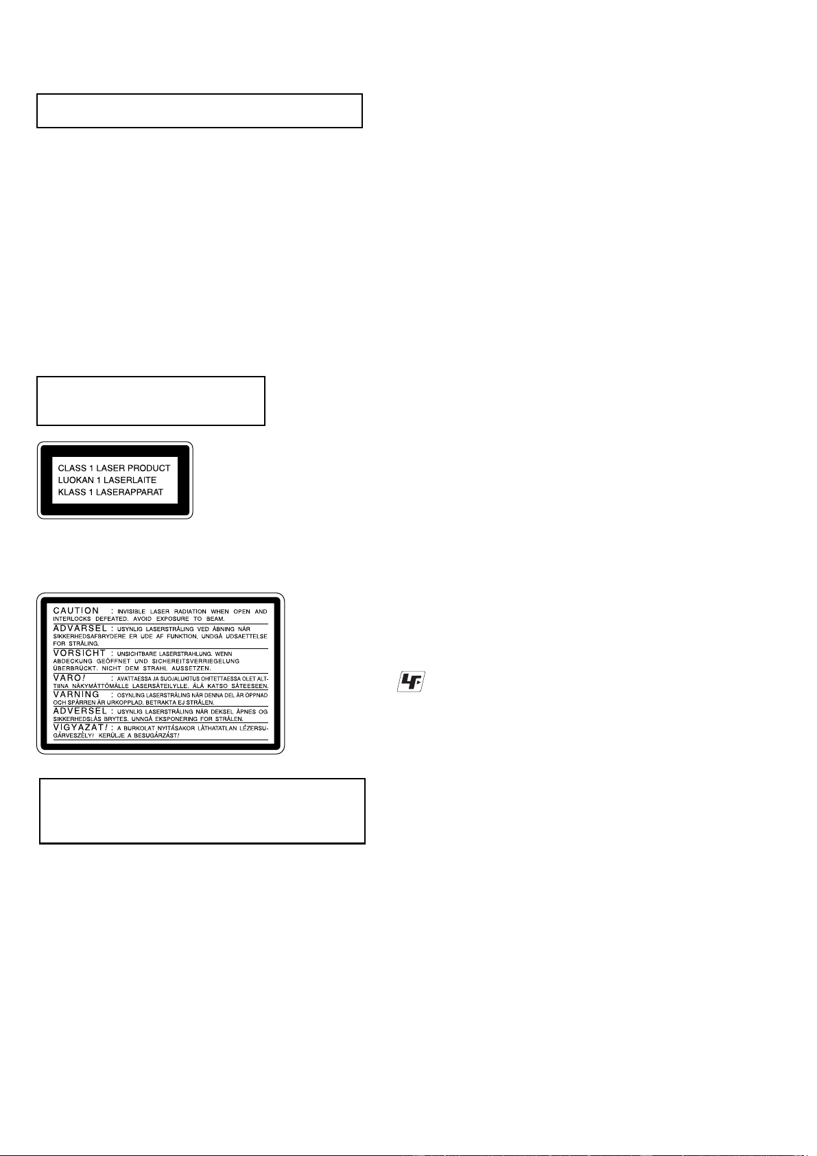
This appliance is classified as a CLASS 1 LASER product. The
CLASS 1 LASER PRODUCT MARKING is located on the rear
exterior.
Laser component in this product is capable
of emitting radiation exceeding the limit for
Class 1.
CAUTION
Use of controls or adjustments or performance of procedures
otherthan those specified hereinmay result in hazardousradiation
exposure.
Notes on chip component replacement
•Never reuse a disconnected chip component.
•Notice that the minus side of a tantalum capacitor may be
damaged by heat.
Flexible Circuit Board Repairing
•Keep the temperature of soldering iron around 270˚C
during repairing.
•Do not touch the soldering iron on the same conductor of the
circuit board (within 3 times).
•Be careful not to apply force on the conductor when soldering
or unsoldering.
ATTENTION AU COMPOSANT AYANT RAPPORT
À LA SÉCURITÉ!
LES COMPOSANTS IDENTIFÉS PAR UNE MARQUE 0SUR LES
DIAGRAMMES SCHÉMATIQUES ET LA LISTE DES PIÈCES SONT
CRITIQUES POUR LA SÉCURITÉ DE FONCTIONNEMENT. NE
REMPLACER CES COMPOSANTS QUE PAR DES PIÈSES SONY
DONT LES NUMÉROS SONT DONNÉS DANS CE MANUEL OU
DANS LES SUPPÉMENTS PUBLIÉS PAR SONY.
SAFETY-RELATED COMPONENT WARNING!!
COMPONENTS IDENTIFIED BY MARK 0OR DOTTED LINEWITH
MARK 0ON THE SCHEMATIC DIAGRAMS AND IN THE PARTS
LIST ARE CRITICAL TO SAFE OPERATION. REPLACE THESE
COMPONENTS WITH SONY PARTS WHOSE PART NUMBERS
APPEAR AS SHOWN IN THIS MANUAL OR IN SUPPLEMENTS
PUBLISHED BY SONY.
Unleaded solder
Boards requiring use of unleaded solder are printed with the lead-
free mark (LF) indicating the solder contains no lead.
(Caution: Some printed circuit boards may not come printed with
the lead free mark due to their particular size.)
: LEAD FREE MARK
Unleaded solder has the following characteristics.
•Unleaded solder melts at a temperature about 40°C higher than
ordinary solder.
Ordinary soldering irons can be used but the iron tip has to be
applied to the solder joint for a slightly longer time.
Soldering irons using a temperature regulator should be set to
about 350°C.
Caution: The printed pattern (copper foil) may peel away if the
heated tip is applied for too long, so be careful!
•Strong viscosity
Unleaded solder is more viscous (sticky, less prone to flow) than
ordinary solder so use caution not to let solder bridges occur such
as on IC pins, etc.
•Usable with ordinary solder
It is best to use only unleaded solder but unleaded solder may
also be added to ordinary solder.
NOTES ON HANDLING THE OPTICAL PICK-UP
BLOCK OR BASE UNIT
The laser diode in the optical pick-up block may suffer electrostatic
break-down because of the potential difference generated by the
charged electrostatic load, etc. on clothing and the human body.
During repair, pay attention to electrostatic break-down and also
use the procedure in the printed matter which is included in the
repair parts.
The flexible board is easily damaged and should be handled with
care.
NOTES ON LASER DIODE EMISSION CHECK
The laser beam on this model is concentrated so as to be focused on
the disc reflective surface by the objective lens in the optical pick-
up block. Therefore, when checking the laser diode emission,
observe from more than 30 cm away from the objective lens.
SECTION 1
SERVICING NOTES
This caution
label is
located inside
the unit.

5
HCD-CQ1
Service position of the Overall
Service position of the CD Mechanism Deck
PANEL boar
d
CONTROL board
REMOCON board
POWER board power transformer
JACK board
CD mechanism
TUNER

6
HCD-CQ1 SECTION 2
GENERAL This section is extracted
from instruction manual.
Main unit
DIMMER 1(13)
Display window 8
FUNCTION 2(6, 7, 14, 16)
Remote sensor 0
TUNING +/– 4(8, 10)
VOLUME +/– 3(11)
?/1 (power) 9(4, 5, 9, 11, 14,
16)
./> (go back/go forward)
4(5, 6, 7, 9, 11)
x(stop) 5(6, 14, 16)
NX (play/pause) 6(6, 7)
Z(open/close) 7(6)
List of button locations and reference pages
How to use this page
Use this page to find the location of buttons and other
parts of the system that are mentioned in the text.
Ill
us
t
ra
ti
on num
b
er
r
FUNCTION 2(6, 7, 14, 16)
RR
Name of button/part Reference page
ALPHABETICAL ORDER
A – F R – Z
BUTTON DESCRIPTIONS
9
1
2
3
4
876
5 q;

7
HCD-CQ1
Remote control
BALANCE 0(10)
BASS 6(10)
CENTER 7(10)
CLEAR wh (8)
CLOCK/TIMER SELECT wj
(12)
CLOCK/TIMER SET qg (5, 11)
DISPLAY qd (12, 13)
DSG 8(10)
ENTER qh (5, 7, 9, 11)
EQ + 5(10)
EQ – 9(10)
FM MODE qk (10)
FUNCTION ws (6, 7, 14, 16)
PLAY MODE wd (6, 7)
REPEAT qk (7)
SLEEP qf (11)
TREBLE 4(10)
TUNER BAND qa (8, 10)
TUNER MEMORY ql (8)
TUNING MODE wd (8, 10)
TUNING +/– 3(8, 10)
VOL + w; (11)
VOL – wa (11)
?/1 (power) 1(4, 5, 9, 11, 16)
m/M (fast forward/rewind)
2(5, 6)
./> (go back/go forward)
3(5, 6, 7, 9, 11)
x(stop) qj (6, 16)
X(pause) wg (6)
CD N(play) wf (6, 7)
OPEN/CLOSE Z(open/close)
qs (6)
ALPHABETICAL ORDER
A – E F – Z
BUTTON DESCRIPTIONS
1
2
3
4
5
678
9
q;
qa
qs
qd
qf qg
qh
qj
wf
wd
ql
w;
wa
ws
wh
wj
qk
wg

8
HCD-CQ1
Inserting two R6 (size AA)
batteries into the remote
Note
If you do not use the remote for a long period of time,
remove the batteries to avoid possible damage from
battery leakage and corrosion.
Tip
When the remote no longer operates the system,
replace both batteries with new ones.
Use buttons on the remote for the operation.
1Press ?/1 to turn on the system.
2Press CLOCK/TIMER SET.
3Press ./> repeatedly to set the
hour.
4Press ENTER or M.
5Press ./>> repeatedly to set the
minute.
6Press ENTER.
The clock starts working.
To adjust the clock
1
Press CLOCK/TIMER SET.
2
Press ./> repeatedly to select
“CLOCK”, then press ENTER.
3
Do the same procedures as step 3 to 6
above.
E
e
eE
Setting the clock

9
HCD-CQ1
SECTION 3
DISASSEMBLY
•The equipment can be removed using the following procedure.
PANEL (BACK)
PANEL (TOP) ASSY
PANEL BOARD
TUNER (FM/AM)
POWER BOARD
CONTROL BOARD
REMOCON BOARD,
PANEL (FRONT) ASSY
JACK BOARD,
REG BOARD BEARING ASSY,
BUSHING (GUIDE A)
BD BOARD
OPTICAL PICK-UP
(KSM-213DCP/Z-NP)
KSS-213D/Q-RP
SLIDER (R),
SLIDER (L)
LOADING BOARD,
GEAR (P),
GEAR (M)
TRAY
CD MECHANISM DECK
(CDM76-K6BD44S)
SET
Note : Follow the disassembly procedure in the numerical order given.
3-1. Panel (Back)
2
six screws
(+BVTP 3
×
8)
1
three screws
(+BVTP 3
×
10)
Note
When removing the panel (back),
do not remove this screw.
(This screw fastens the
tuner (FM/AM) pack.)
3
panel (back)
4
panel (back) top

10
HCD-CQ1
3-2. Panel (Top) Assy
2
Insert a screwdriver of 4mm diameter and release the
claws by raising the panel (top) assy gently.
7
FFC 33p (425)
8
panel (top) assy
6 cm
13 cm
6 cm
13 cm
3
4
5
1
6
(Location of the claws.)
If the main power cannot be turned on,
slide the CDM chassis using a screwdriver
in order to raise the panel (top) assy.

11
HCD-CQ1
3-3. PANEL Board
3-4. CD Mechanism Deck (CDM76-K6BD44S)
1
two screws
(+BTP 2
×
4)
2
four screws
(+PTPWH M2.6)
3
four bushings (PWB)
4
PANEL board
5
panel (top) ass
y
3
FFC 21p (150)
5
CD mechanism deck
(CDM76-K6BD44S)
2
1
screw
(+BVTP 3
×
8)
4
connector (CN1)

12
HCD-CQ1
3-5. JACK Board, REG Board
3-6. Bearing Assy, Bushing (Guide A)
2
FFC 11p (180)
3
JACK board
6
REG board
1
screw
(+BVTP 3
×
8)
4
screw
(+BVTP 3
×
8)
5
connector (CN961)
5
two screws
(+BVTP 3
×
8)
9
three screws
(+BVTP 3
×
8)
1
screw
(+BVTP 3
×
8)
qa
two screws
(+BVTT 3
×
6)
qs
two screws
(+BVTP 2.6
×
8)
q;
screw
(+BVTP 3
×
8)
qf
chassis
(CDM)
2
chassis
(guide L)
6
chassis
(guide R)
8
bushing
(guide A)
7
two claws
4
bearing assy
3
three screws
(+BTTP M2.6)
qd
guide (front panel)

13
HCD-CQ1
3-7. Tuner (FM/AM)
3-8. POWER Board
2
FFC 11p (175)
3
tuner (FM/AM)
1
screw
(+BVTP 3
×
8
)
6
four screws
(+BVTT 3
×
6)
7
sub plate
8
power transformer
(T901)
4
connector
(CN902)
5
connector
(CN903)
1
FFC 31p (150)
5
screw
(+BVTP 3
×
8)
4
two screws
(+BVTP 3
×
8
)
2
connector (CN901)
3
power cord
6
POWER board

14
HCD-CQ1
3-9. REMOCON Board, Panel (Front) Assy
3-10. CONTROL Board
1
two screws
(+BVTP 2.6
×
8
)
4
two screws
(+BVTP 2.6
×
8)
7
screw
(+BVTP 2.6
×
8)
2
clamp (L35)
6
panel (front) assy
8
panel (side-L)
3
connector (CN253)
5
REMOCON board
2
two screws
(+BTTP M2.6)
1
screw
(+BVTP 2.6
×
8)
4
panel (side-R )
3
CONTROL board

15
HCD-CQ1
3-11. Optical Pick-Up (KSM-213DCP/Z-NP)
1
two screws (DIA.12)
6
two screws (DIA.12)
2
coil spring (insulator)
7
two coil springs (insulator)
4
coil spring (insulator)
3
insulator
8
two insulators
5
insulator
9
optical pick-up
(KSM-213DCP/Z-NP)
3-12. BD Board
3
wire (flat type)
(16 core)
5
optical pick-up
(KSM-213DCP/Z-NP)
2
screw
(+BVTP 2.6
×
8)
4
BD board
1
Remove four solders
of motor.

16
HCD-CQ1
3-14. Slider (R), Slider (L)
2
guide (R)
8
guide (L)
6
slider (R)
qs
slider (L)
1
two screws
(+BVTP 2.6
×
8
)
7
two screws
(+BVTP 2.6
×
8)
3
screw
(+PTPWH M2.6)
9
screw
(+PTPWH M2.6)
qa
two brackets
5
two brackets
qf
MD base
qd
slider (S)
4
two screws
(DIA.12)
q;
two screws
(DIA.12)
CDM76-K6BD44S
3-13. KSS-213D/Q-RP
2
gear (A)
1
claw
5
sled shaft
6
KSS-213D/ Q-RP
4
3

17
HCD-CQ1
3-16. LOADING Board, Gear (P), Gear (M)
1
belt (CDM55)
5
pulley (LDG)
8
gear (M)
9
torsion sprin
g
q;
lever (sw)
7
gear (P)
4
stop ring 2.0 type-E
3
LOADING board
2
three screws
(+P 2.6
×
8)
6
screw
(+PTPWH M2)
3-15. Tray
A
1
magnet assy
2
pulley (AT) ass
y
5
tray
4
4
3
Rotate the pulley (LDG) in
the direction of arrow
A
.

18
HCD-CQ1
[MCTEST MODE]
•This mode is used to check operations of Amplifier.
Procedure:
1. Press the ?/1key to turn the power ON.
2. Press three keys of [VOLUME-],xand ?/1simultaneously.
3. When the MC test mode is activated, “MIN” is displayed on the
liquid crystal display.
4. Press the [VOLUME+] key, “MAX” is displayed on the liquid
crystal disply.
Press the [VOLUME-] key, “MIN” is displayed.
5. To release this mode, press the ?/1key.
[PANEL (GC)TEST MODE]
•This mode is used to check the liquid crystal display, LED,
model, destination, software version and key.
Procedure:
1. Press the ?/1key to turn the power ON.
2. Press three keys of [VOLUME+],xand ?/1simultaneously.
3. Liquid crystal display and LED are all turned on.
4. When you want to enter the model, destination and version
display mode, press the ukey. The model and destination
are displayed alternately on the liquid crystal display.
5. Each time ukey is pressed, the MC version or CD version
is displayed on the liquid crystal display.
6. When >keyis pressed while the version numbers are being
displayed except model and destination, year, month and day
of the software creation display. When >key is pressed
again, the display returns to the software version display.When
ukey is pressed while year, month and day of the software
creationarebeingdisplayed,the year,month and day of creation
of the software versions are displayed on the liquid crystal
display in the same order of version display.
7. Press the .key, the key check mode is activated.
8. In the key check mode, the liquid crystal display displays “K0”
on the liquid crystal display. Each time a key is pressed, “K”
value increases. However, once a key is pressed, it is no longer
taken into account.
9. To release this mode, press three keys in the same manner as
step 2, or disconnect the power cord.
[COLD RESET]
•The cold reset clears all data including preset data stored in the
RAM to initial conditions. Execute this mode when returning
the set to the customer.
Procedure:
1. Press the ?/1key to turn the power ON.
2. Press three keys of [FUNCTION], xand ?/1simultaneously.
3. The liquid crystal display becomes blank instantaneously, and
the set is reset.
[CDTRAY LOCK MODE]
•This mode is used to unable to take sample disc out of tray in
the shop.
Procedure:
1. Press the ?/1key to turn the power ON.
2. Press the [FUNCTION] key to select “CD”.
3. While pressing the Zkey, press the xkey for 5 seconds.
4. The message “LOCK” is displayed on the liquid crystal display
and the tray is locked. (Even if pressing the Zkey, the message
“LOCK” is displayed on the liquid crystal display and the tray
is locked)
5. To release from this mode, pressing the Zkey, press the x
key for 5 seconds.
6. The message “FREE” is displayed on the liquid crystal display
and the tray is unlocked.
[CD SERVICE MODE]
•This mode can run the CD sled motor freely. Use this mode, for
instance, when cleaning the optical pick-up.
Procedure:
1. Press ?/1key to turn the power ON.
2. Press the [FUNCTION] key to select “CD”.
3. Press three keys of x, [DIMMER] and [FUNCTION]
simultaneously.
4. Press >key to move the optical pick-up to outside track, or
press .key to inside track.
5. To release this mode, press the ?/1key.
[AGING MODE]
•This mode can be used for operation check of CD section.
If an error occurred:
The aging operation stops only an error occurred.
If no error occurs:
The aging operation continues repeatedly.
Procedure:
1. Press the ?/1key to turn the power ON.
2. Press the [FUNCTION] key to select “CD”.
3. Set disc on the tray.
4. Press three keys of [VOLUME-], u and ?/1
simultaneously.
5. Aging operation of CD is started.
6. To release this mode, press the ?/1key.
CD Aging Sequence
The sequence during the aging mode is following as below.
Display at the aging mode is the same as the normal operation.
Agingmodesequence:
Start
Disc chucking
TOC read
Play first track for 2 seconds
Play last track for 2 seconds
Open the disc tray
Close the disc tray
SECTION 4
TEST MODE
This manual suits for next models
2
Table of contents
Other Sony Stereo System manuals

Sony
Sony SRS-X33 User manual

Sony
Sony CX-JN5 User manual

Sony
Sony HCD-RV222 User manual

Sony
Sony CMT-DX400 User manual

Sony
Sony CMT-SE9 User manual

Sony
Sony MHC-GX470 - Mini Hi Fi Stereo System User manual

Sony
Sony HCD-GN700 User manual

Sony
Sony MEX-XB100BT User manual

Sony
Sony HCD-D60 User manual

Sony
Sony CMT-GPX5 User manual

Sony
Sony MHC-G101 Primary User manual

Sony
Sony SRS-X5 User manual

Sony
Sony HCD-GRX33 - Component For Mhcrx33 User manual

Sony
Sony SHAKE-X30 User manual

Sony
Sony CMT-GS10 User manual

Sony
Sony MHC-VX222 User manual

Sony
Sony hcd-tb20 User manual

Sony
Sony CMT-SBT100 User manual

Sony
Sony SHAKE-X30D User manual

Sony
Sony HCD-RG190 User manual