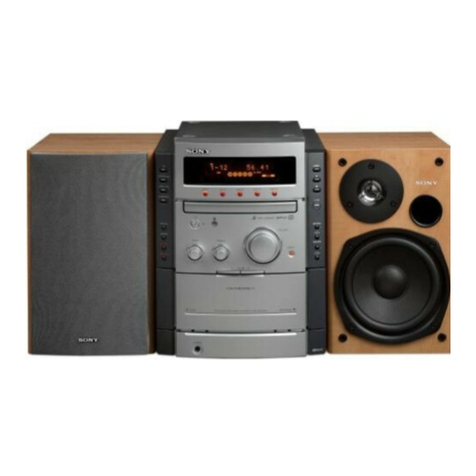
Sony MHC-GPX5 Building instructions

MANUAL'(6(59,d2
Published by Sony EMCS (Malaysia) PG Tec
Sony Corporation
A-1857-711-A SPACER A, ASSY (GPX8P)
A-1857-712-A SPACER B, ASSY (GPX8P)
1-490-185-11 REMOTE COMMANDER (RM-AMU140)
(including BATERY LID)
1-754-399-21 ANTENNA, ROOP (AM loop antenna (aerial))
4-412-606-12 MANUAL, INSTRUCTION (ENGLISH)
(EXCEPT MX)
4-412-606-22 MANUAL, INSTRUCTION (FRENCH, SPANISH)
(E2)
4-412-606-32 MANUAL, INSTRUCTION (SPANISH) (E51)
4-412-606-42 MANUAL, INSTRUCTION
(FRENCH, PORTUGUESE, ARABIC) (E4)
4-412-606-71 MANUAL DE INSTRUÇÕES (PORTUGUÊS)
(GPX8G/GPX7G/GPX5G) (BR)
• HCD-GPX7G is composed of HCD-GPX7G.
• HCD-GPX8G is composed of HCD-GPX8G.
• SS-GPX7P is composed of SS-GPX7.
• SS-GPX8P is composed of SS-GPX8, SS-WGP8 and SS-RSP8.
MINI HI-FI COMPONENT SYSTEM
9-890-599-01
2012C08-1
© 2012.03
E Model
Ver. 1.0 2012.03
• MHC-GPX5/GPX7/GPX8 are composed of
following models.
As service manuals are issued for each component model,
please refer to them.
General
Power requirements
Mexican model: AC 120 V – 240 V, 60 Hz
Other models: AC 120 V – 240 V, 50/60 Hz
Power consumption
MHC-GPX8: 250 W
MHC-GPX7: 230 W
MHC-GPX5: 200 W
Dimensions (w/h/d) (excl. speakers)
(Approx.)
280 mm × 355 mm × 440 mm
Mass (excl. speakers) (Approx.)
HCD-GPX8G/HCD-GPX7G/
HCD-GPX5G: 7.0 kg
Supplied accessories
Remote control (1)
R6 (Size AA) batteries (2)
FM lead/AM loop antenna (1)
Spacer A (MHC-GPX8 only) (2)
Spacer B (MHC-GPX8 only) (2)
Speaker pads (MHC-GPX7 only) (8)
Design and specifications are subject to change without notice.
• Abbreviation
E2 : 120V AC area in E model
E4 : African model
E51 : Chilean and Peruvian models
BR : Modelo Brasil
ACCESSORIES
Ref. No. Part No. Description Remark
COMPONENT MODEL NAME
MHC-GPX5 MHC-GPX7 MHC-GPX8
PACKAGE – HCD-GPX7G HCD-GPX8G
COMPACT DISC RECEIVER HCD-GPX5G HCD-GPX7G HCD-GPX8G
PACKAGE SPEAKER – SS-GPX7P SS-GPX8P
FRONT SPEAKER SS-GPX5 SS-GPX7 SS-GPX8
SUBWOOFER SS-WGP5 – SS-WGP8
SATELLITE SPEAKER – – SS-RSP8
SPECIFICATIONS
MHC-GPX5/GPX7/GPX8
HCD-GPX7G/HCD-GPX8G

MANUAL'(6(59,d2
Sony Corporation
Published by Sony EMCS (Malaysia) PG Tec
HCD-GPX5G/GPX7G/GPX8G
(SPECIFICAd®(6
9-890-600-01
2012C08-1
© 2012.03
Modelo BR
Ver. 1.0 2012.03
• HCD-GPX5G is the amplifier, USB, CD player and tuner
section in MHC-GPX5.
• HCD-GPX7G is the amplifier, USB, CD player and tuner
section in MHC-GPX7.
• HCD-GPX8G is the amplifier, USB, CD player and tuner
section in MHC-GPX8. Photo: HCD-GPX8G (Modelo BR)
“WALKMAN” and “WALKMAN” logo are registered
trademarks of Sony Corporation.
MPEG Layer-3 audio coding technology and patents licensed
from Fraunhofer IIS and Thomson.
Windows Media is either a registered trademark or trademark
of Microsoft Corporation in the United States and/or other
countries.
This product contains technology subject to certain
intellectual property rights of Microsoft.
Use or distribution of this technology outside of this product
is prohibited without the appropriate license(s) from
Microsoft.
CD Section
Model Name Using Similar Mechanism
NEW
CD Mechanism Type
CDM74I-DVBU201//M
Optical Pick-up Name CMS-ST6RFS3
COMPACT DISC RECEIVER
Amplifier section
The following are measured at Mexican model:
AC 120 V – 240 V, 60 Hz
Other models:
AC 120 V – 240 V, 50/60 Hz
MHC-GPX8
Front/Satellite/Subwoofer speaker
Power Output (rated): 1200W
Front speaker
RMS output power (reference):
270 W + 270 W (per channel at 6 ohms,
1 kHz, 10% THD)
Satellite speaker
RMS output power (reference):
135 W+ 135 W (per channel at 12 ohms,
1 kHz, 105 THD)
Subwoofer
RMS output power (reference):
195 W + 195 W (per channel at 8 ohms,
100 Hz, 10% THD)
MHC-GPX7
HIGH speakers
Power Output (rated): 1100W
RMS output power (reference):
400 W + 400 W (per channel at 4 ohms,
1 kHz, 10% THD)
LOW speakers
RMS output power (reference):
150 W + 150 W (10 ohms, 100 Hz, 10% THD)
MHC-GPX5
Front speaker
Power Output (rated): 900W
RMS output power (reference):
300 W + 300 W (per channel at 5 ohms,
1 kHz, 10% THD)
Subwoofer
RMS output power (reference):
300 W (5 ohms, 100 Hz, 10% THD)
Inputs
TV (AUDIO IN) L/R
Voltage 1.2 V, impedance 47 kilohms
DVD/SAT (AUDIO IN) L/R
Voltage 1.2 V, impedance 47 kilohms
PC/GAME (AUDIO IN) L/R
Voltage 1.2 V, impedance 47 kilohms
MIC (MHC-GPX8/MHC-GPX7 only)
Sensitivity 1 mV, impedance
10 kilohms
A (USB), B (USB) port: Type A
USB section
Supported bit rate
MP3 (MPEG 1 Audio Layer-3):
32 kbps – 320 kbps, VBR
WMA: 48 kbps – 192 kbps
AAC: 48 kbps – 320 kbps
Sampling frequencies
MP3 (MPEG 1 Audio Layer-3):
32 kHz/44.1 kHz/48 kHz
WMA: 44.1 kHz
AAC: 44.1 kHz
Supported USB device
Mass Storage Class
Maximum current
500 mA
Disc player section
System
Compact disc and digital audio system
Laser Diode Properties
Emission Duration: Continuous
Laser Output*: Less than 44.6 μW
* This output is the value measurement
at a distance of 200 mm from the
objective lens surface on the Optical
Pick-up Block with 7 mm aperture.
Frequency response
20 Hz – 20 kHz
Signal-to-noise ratio
More than 90 dB
Dynamic range
More than 88 dB
Tuner section
FM stereo, FM/AM superheterodyne tuner
Antenna:
FM lead antenna
AM loop antenna
FM tuner section
Tuning range
87.5 MHz – 108.0 MHz (100 kHz step)
AM tuner section
Tuning range
Pan American models:
530 kHz – 1,710 kHz (10 kHz step)
531 kHz – 1,710 kHz (9 kHz step)
Other models:
530 kHz – 1,610 kHz (10 kHz step)
531 kHz – 1,602 kHz (9 kHz step)
General
Power requirements
Mexican model: AC 120 V – 240 V, 60 Hz
Other models: AC 120 V – 240 V, 50/60 Hz
Power consumption
MHC-GPX8: 250 W
MHC-GPX7: 230 W
MHC-GPX5: 200 W
Dimensions (w/h/d) (excl. speakers)
(Approx.)
280 mm × 355 mm × 440 mm
Mass (excl. speakers) (Approx.)
HCD-GPX8G/HCD-GPX7G/
HCD-GPX5G: 7.0 kg
Supplied accessories
Remote control (1)
R6 (Size AA) batteries (2)
FM lead/AM loop antenna (1)
Spacer A (MHC-GPX8 only) (2)
Spacer B (MHC-GPX8 only) (2)
Speaker pads (MHC-GPX7 only) (8)
Design and specifications are subject to change
without notice.

HCD-GPX5G/GPX7G/GPX8G
2
5E3$5$(03/$&$6'(&,5&8,72)/(;Ë9(/
• 0DQWHUD temperaturDGR IHUURGHVROGDU HPWRUQRGH 270 °C
GXUDQWHRUepaUR.
• 1mRWRTXHFRPRIHUURGHVROGDURPHVPRFRQGXWRUFKLSGD
SODFD (PDLVGH 3 YH]HV).
• 7HQKDFXLGDGRSDUDQmRDSOLFDU foroD QR condutorFKLSTXDQGR
VROGDURXGHVVROGDU.
$7(1d2&2026&20321(17(6'(6(*85$1d$!
OS COMPONENTES IDENTIFICADOS COM A MARCA 0
0NOSDIAGRAMAS ESQUEMÃTICOS E NA LISTA DE PEÇAS
SÃO CRÍTICOS PARA SEGURANÇA. SOMENTE OS SUBSTITUA
POR PEÇAS NUMERICAMENTE IDENTIFICADAS NESSE MANUAL
OUEM SUPLEMENTOS PUBLICADOS PELA SONY.
ATENÇÃO
O uso dos controles ou ajustes ou o desempenho dos procedi-
mentos a exceção daqueles especificados para isto podem
resultar na exposição de radiatição perigosa.
9(5,),&$d2'(6(*85$1d$
$SyVWHUFRUULJLGRRSUREOHPDRULJLQDOGRVHUYLoRH[HFXWDDVHJXLQWH
YHULILFDomRGHVHJXUDQoDDQWHVGHOLEHUDURDSDUHOKRSDUDRFRQVXPLGRU:
ChecDU RWHUPLQDOGD antena, metal FRUWDQWH, ERW}HV“metalizDdRV”,
SDUDIXVRV, HWRGDVDVSHoDVPHWiOLFDVH[SRVWDV SDUDIXJDAC.
ChecDUIXJD$& FRQIRUPHDGHVFULomRDEDL[R.
7(67('()8*$$&
$IXJD AC GHWRGDVDVSDUWHVPHWiOLFDVH[SRVWDVDWHUUDQmRGHYH
H[FHGHUPLOLDPSHUHVPLFURDPSHUHV
$IXJDGHFRUUHQWHSRGHVHUPHGLGDXVDQGRDOJXPGRVWUrV metodRs.
1. 8PWHVWHcommercial GHIXJD, WDOFRPRR Simpson 229 RX RCA
WT-540A. 6LJDDVLQVWUXo}HVGRVIDEULFDQWHVSDUDXVDUHVWHV
instrumentRs.
2. 8PPLOLDPSHULPHWUR ACRSHUDGRSRUEDWHULD. 8PPXOWLPHWUR
digital GHSUHFLVmRpDSURSULRDGRSDUDHVWHWUDEDOKR.
3. MeGLU Dvoltage FRPRFLUFXLWRDRODGRVREUHRresistor SRU
GHXPVOM RX $&YROWLPHWURRSHUDGRUSRUbaterLD. 2“limitH”
LQGLFDGRp 0.75 V, HQWmR RVPHGLGRUHVDQDOyJLFRVGHYHPWHU XPD
HscalDGHEDL[DYROWDJHPH[DWD. 2Simpson 250 HSanwa SH-63Trd
VmRH[HPSORVGHXP920 passivRDSURSULDGR. 4XDVHWRGRVRV
multimetRsGLJLWDLVRSHUDGRVDEDWHULDWHPXPDHVFDOD$&GH 2 V
DSURSULDGD. (9HMDDILJXUD$
1.5 kΩ0.15 μF
AC
voltmeter
(0.75 V)
3DWHV0HWiOLFDV([SRVWDV
no Aparelho
Terra Gnd (Chassi)
Fig. A. UsDQGR XP AC voltLmetrRSDUD checDUIXJDAC.
T Este aparelho é classificado como produto
LASER CLASSE 1. Esta etiqueta está
localizada na parte traseira.
.
Notas sobre reparo do componentes do tipo Chip
• Nunca reutilize um componente tipo chip.
• Informamos que o lado menos dos capacitores de tantalo podem ser
danificados se expostos a altas temperaturas.

HCD-GPX5G/GPX7G/GPX8G
3
Ë1',&(
1. 127$6'(6(59,d2............................................... 4
2. D(60217$*(0
2-1. Sequencia de Desmontagem........................................... 8
2-2. Tampa................................................................................. 9
2-3. Painel de carregamento................................................... 9
2-4. Seção Painel Frontal ...................................................... 10
2-5. Seção Mecanismo CD (CDM741-DVBU201//M) ......... 10
2-6. Placa TUNER1AM3R .................................................... 11
2-7. Placa MAIN .................................................................... 11
2-8. Seção Painel Traseiro ..................................................... 12
2-9. Placa 4CH DAMP .......................................................... 13
2-10. Seção Chassi ................................................................... 14
2-11. Tampa Dust CDM ........................................................... 15
2-12. Unidade Otica .................................................................. 15
2-13. Placa DMB22 ................................................................. 16
2-14. Placa DRIVER, PlacaSWITCH ...................................... 16
2-15. Placa SENSOR ............................................................... 17
2-16. Placa MOTOR (TB)........................................................ 17
2-17. Placa MOTOR (LD) ...................................................... 18
3. 02'2'(7(67(.................................................... 19
4. VERIFICAÇÃO ELÉTRICA................................... 22
5. DIAGRAM$S
5-1. Diagrama em bloco - Seção CD/USB ............................. 23
5-2. Diagrama em bloco - Seção MAIN.................................. 24
5-3. Diagrama em bloco - Seção AMP ................................... 25
5-4. DiagramaHPEORFR - 6HomRPAINEL/Fonte de Alimentação 6
5-5. Placa de circuito Impresso -
Placa 4CH DAMP ( lado Componente) ......................... 28
5-6. Placa de circuito Impresso -
Placa 4CH DAMP (lado CREUHDGR)............................... 29
5-7. Diagrama Esquemático - Placa 4CH DA0P (1/3) -...... 30
5-8. Diagrama Esquemático - Placa 4CH DAMP (2/3) -....... 31
5-9. Diagrama Esquemático - Placa 4CH DAMP (3/3) -....... 32
5-10. Placa de circuito Impresso - Placa DISPLAY - .............. 33
5-11. Diagrama Esquemático - Placa DISPLAY -.................... 34
5-12. Placa de circuito Impresso -
Placa MAIN (Lado Componente) ................................... 35
5-13. Placa de circuito Impresso -
Placa MAIN (Lado CoEUHDGR) ........................................ 36
5-14. Diagrama Esquemático - Placa MAIN (1/4) -................. 37
5-15. Diagrama Esquemático - Placa MAIN (2/4) - ................ 38
5-16. Diagrama Esquemático - Plava MAIN (3/4) - ................ 39
5-17. Diagrama Esquemático - Placa MAIN (4/4) - ................ 40
5-18. Placa de circuito Impresso -
Placas USB, VOLUME eMIC - ...................................... 41
5-19. Diagramas Esquemáticos-
Placas USB, VOLUME eMIC - ...................................... 42
5-20. Placas de circuito Impresso - Placas DRIVER, SENSOR,
SWITCH, MOTOR (LD) eMOTOR (TB) ..................... 43
5-21. Diagramas Esquemáticos- Placas DRIVER, SENSOR,
SWITCH, MOTOR (LD) eMOTOR (TB) - .................... 44
5-22. Placa de circuito Impresso - Placa TUNER1AM3R ...... 45
5-23. Diagrama Esquemático - Placa TUNER1AM3R............ 45
5-24. Placa de circuito Impresso - Placa DMB22.................... 46
5-25. Diagrama Esquemático - Placa DMB22 (1/3) -.............. 47
5-26. Diagrama Esquemático - Placa DMB22 (2/3) -.............. 48
5-27. Diagrama Esquemático - Placa DMB22 (3/3) -.............. 49
6. VIS7$(;3/2','$
6-1. Seção Tampa ................................................................... 61
6-2. Seção Painel Frontal ...................................................... 62
6-3. Seção Painle Traseiro ..................................................... 63
6-4. Seção Chassi ................................................................... 64
6-5. Seção Mecanismo CD (1)
(CDM74I-DVBU201//M)............................................... 65
6-6. Seção Mecanismo CD (2)................................................ 66
7. LIST$'(3(d$6(/e75,&$6......................... 67
5-28. Diagrama Esquemático - Placa SMPS 3H384W -........... 5
5-. Diagrama Esquemático - Placa SMPS 3H385W -........... 55
&$,;$$&Ò67,&$666*3;*3;*3;*3;563. 7
D,$*5$0$6.............. 8
Diagrama Esquemático - ............. 9
3ODFDGHFLUFXLWRLPSUHVVR - Placa 63.5*%/('.......... 9
Diagrama Esquemático - Placa 63.5*%/('.............. 9
9,67$(;3/2','$66*3;*3;..............
9,67$(;3/2','$66*3;..............
9,67$(;3/2','$66*3;..............
9,67$(;3/2','$66563..............
/,67$'(3(d$6(/e75,&$6..............
D,$*5$0$666:*3:*3..............
9,67$(;3/2','$66:*3.............
9,67$(;3/2','$66:*3............
/,67$'(3(d$6(/e75,&$6
&$,;$6$&Ò67,&$6

HCD-GPX5G/GPX7G/GPX8G
4
SEd2 1
NOT$S'(6(59,d2
NOT$62%5(5(3$5212IC502 '$3/$&$DMB22
O IC502 da Placa DMB22 não pode ser trocado apenas ele.
Quando essa peça da placa DMB22 estiver danificada,
trocar a Placa montada inteira.
RE$LI6$5 275$9$0(172'$ %$1'(-$'26',6&26
A função de travamento da bandeja dos discos deve ser utilizada
para evitar o roubo dos discos em lojas de departamento.
ReDliVDQGRR ProcedLPHQWR:
1. Pressionar o botão [I/1STANDBY] para ligar o aparelho.
2. Pressionar o botão [CD/DISC SKIP] para selecionar a função CD.
3. Manter pressionado o botão [x], e pressionar o botão [ENTER] por
mais 5 segundos).
4. A menssagem “LOCKED” aparece no display e a bandeja de disco esta
travada.
NotD:
tDPEpPpGHVDWLYDGD
IDENTIFICAd2'202'(/2
– PaLnel7UDVHLUR –
ModelRPart No.
HCD-GPX8G: E2, E51, E4, BR 4-411-595-0[]
HCD-GPX7G: E2, E51,BR 4-411-595-1[]
HCD-GPX5G: E2, E51,BR 4-411-595-2[]
HCD-GPX8G: MX 4-411-595-3[]
HCD-GPX7G: MX 4-411-595-4[]
HCD-GPX5G: MX 4-411-595-5[]
PART No.
SOLDA SEM CHUMBO
Placas que exigem o uso de solda sem chumbo são impressas com
a marca LF (lead free) indicando que a solda não contém chumbo.
(Atenção: Algumas placas de circuito impresso não podem ter essa
marca devido ao seu tamanho reduzido.)
: IDENTIFICAÇÃO DA SOLDA SEM CHUMBO
A solda livre de chumbo tem as seguintes características:
• Derrete a uma temperatura 40 °C maior que a solda comum.
Ferros de solda comuns podem ser usados mas a ponta tem que
ser aplicada por um tempo maior.
Ferros de solda com regulagem de temperatura devem ser ajusta-
do no valor de 350 °C.
Atenção: A impressao da placa (trilhas de cobre) pode se sol-
tar se a ponta permanecer por muito tempo. Tenha cuidado!
• É mais viscosa
A solda livre de chumbo é mais viscosa (flui com menor faci-
lidade) que a solda comum, portanto tenha cuidado com as
pontes de solda, especialmente entre os pinos de IC's.
• Pode ser utilizada com solda comum
É melhor usar apenas solda sem chumbo mas este tipo também
pode ser adicionado a solda comum.
NOTAS SOBRE O MANUSEIO DA BLOCO DE
UNIDADE ÏTICA OU UNIDADE BASE
O diodo laser da unidade optica é sensível a descargas eletroestáticas
podendo vir a ser danificado por descargas causadas por roupas
ou mesmo pelo corpo humano. Durante o reparo tenha cuidado pa-
ra não causar danos a unidade, devido a cargas eletroestáticas e siga
corretamente os procedimentos descritos nesse manual para a exe-
cução de reparos e troca de componentes.
As placas de circuito impresso flexíveis sao facilmente danificadas.
Tenha cuidado ao manuseá-las.
NOTAS SOBRE A EMISSÃO DO DIODO LASER
O feixe laser nesse modelo é concentrado de forma a ser
superfície reflexiva do disco, pela lente objetiva da unidade óptica.
Quando observar a emissão do diodo laser, tome o cuidado de estar
no mínimo a 30 cm da lente objetiva.5
5. Para destravar, manter pressionado o botão [x], e pressionar o botão [ENTER] por
mais 5 segundos).
6. A menssagem “UNLOCKED” aparece no display e a bandeja de disco esta
destravada.
4XDQGR o botão [I/1STANDBY] IRUSUHVVLRQDGRDIXQomR/2&.('

HCD-GPX5G/GPX7G/GPX8G
5COMO
&202$%5,5$%$1'(-$ '26',6&2648$1'2 2$3$5(/+2(67,9(5'(6/,*$'2
ENGRENAGEM LADO chassi
Mecanismo CD (CDM74I)
5SARCHAVETIPOFENDA
1Girar a engrenagem na direção da seta.
(A localização da roldana da engrenagem
é no lado de baixo do CDM)

HCD-GPX5G/GPX7G/GPX8G
6
'(6&$55(*$5CAPACITOR3$5$ 35(9(1,5&+248(ELeTRICO
:
&
&
&
C1431
&
:
:
:
:
Antes de verificar a placa 4CH DAMP, fazer a
descarga dos capacitores C1424, C1425, C1431
e C1432 para prevenir choque elétrico.
placa 4CH DAMP
Antes de verificar a placa 6036ID]HUD
descarga do capacitor CSDUD
prevenir choque elétrico.
placa SMPS

HCD-GPX5G/GPX7G/GPX8G
7
PRECA8d2 48$1'2,167$/$5 A N29$ 81,'$'(Ï7,&$/
PRECAUd2 &20(/(75,&,'$'((67È7,&$$17(6'(5(029(52&8572'(62/'$
4XDQGRLQVWDODUDQRYDXQLGDGHyWLFDHODGHYHVHUconectDGDSULPHLUR
DSODFDGHFLUFXLWRLPSUHVVRDQWHVGHUHPRYHURFXUWRGHVROGD
3DUDSUHYHQLUGDQRVFDXVDGRVSHODHOHWULFLGDGHHstiticD.
(1mRGHPRUHPXLWRWHPSRUHPRYHQGRRFXUWRGHVROGDGDXQLGDGHyWLFD
(Não removao curto de solda a unidade ótica não estiver conectada a
placa de circuito impresso.)

HCD-GPX5G/GPX7G/GPX8G
8
SECTION 2
D(60217$*(0
• This set can be disassembled in the order shown below.
2-1. 6(48Ç1&,$'(D(60217$*(0
2-2. CASE
(Page 9)
2-5. CD MECHANISM SECTION
(CDM74I-DVBU201/M)
(Page 10)
2-7. MAIN BOARD
(Page 11)
2-8. BACK PANEL SECTION
(Page 12)
2-9. 4CH DAMP BOARD
(Page 13)
2-10. CHASSIS SECTION
(Page 14)
2-11. COVER DUST CDM
(Page 15)
2-13. DMB22 BOARD
(Page 16)
2-12. OPTICAL PICK UP
(Page 15)
2-15. SENSOR BOARD
(Page 17)
2-14. DRIVER BOARD, SWITCH BOARD
(Page 16)
2-16. MOTOR (TB) BOARD
(Page 17)
2-17. MOTOR (LD) BOARD
(Page 18)
2-6. TUNER1AM3R BOARD
(Page 11)
2-4. FRONT PANEL SECTION
(Page 10)
SET
2-3. LOADING PANEL
(Page 9)

HCD-GPX5G/GPX7G/GPX8G
9
2-3. PA,NEL'(&$55(*$0(172
Note: Follow the disassembly procedure in the numerical order given.
2-2. 7$03$ 5
6
two screws
(+BVTP 3x14)
two screws
(+BVTP 3x14)
1
2two screws
(+BVTP 3x14)
(+BVTP 3x14)
2
3
3
two screws
1two screws
(+BVTP 3x14)
4panel, side (R)
4panel, side (L)
2Pull-out the disc tray
3panel, loading
ENGRENAGEM LADO chassi
Mecanismo CD (CDM74I)
5SARCHAVETIPOFENDA
1Girar a engrenagem na direção da seta.
(A localização da roldana da engrenagem
é no lado de baixo do CDM)

HCD-GPX5G/GPX7G/GPX8G
10
2-5. 6(d20(&$1,602CD (CDM74I-DVBU201//M)
2-4. 6(d23$,1(/FRONTAL
1four screws
(+BVTP 3x8)
1
one screws
(+BVTP 3x8)
For GPX7G/
GPX8G
2one screw
(+BVTP 3x8)
2one screw
(+BVTP 3x8)
5
CN705 (10P)
4
CN707 (4P)
3
wire (flat type) (17core) CN601
CD mechanism section
( CDM74I-DVBU201//M)
Peel off the cushion
and tape on the wire
(flat type) from TUNER.
4one screw
(BVTP 3x8)
2
wire (flat type) (19core) CN702
3
wire (flat type) (15core) CN703
1
wire (flat type) (13core) CN700
tape
cushion

HCD-GPX5G/GPX7G/GPX8G
11
2-6. 3/$&$TUNER1AM3R
2-7. 3/$&$MAIN
2
5
3
4
two screws
(BVTP 3x8)
1wire (flat type) (9 core)
(CN513)
TUNER1AM3R board
shield plate bottom
shield plate top
1two screws
(+BVTP 3x8)
2two screws
(+BVTP 3x8)
3MAIN board

HCD-GPX5G/GPX7G/GPX8G
12
2-8. 6(d2PA,NEL 75$6(,52
6two screws
(BVTP 3x8)
7
8one screws
(BVTP 3x8)
2two screws
(BVTP 3x8)
3two screws
(BVTP 3x8)
one screw
(+BVTP 3x8)
for GPX8G
1CN1405 (3P)
5fan, DC
4cover, fan
9back panel section

HCD-GPX5G/GPX7G/GPX8G
13
2-9. 3/$&$4CH DAMP
3two screws
(BVTT 3x8)
1three screws
(PTPWH 2.6x12)
64CH DAMP board
4
2
CN2 (9P)
5CN3 (5P)
sheet thermal
3two screws
(BVTT 3x8)

HCD-GPX5G/GPX7G/GPX8G
14
2-10. 6(d2CHASSI
6
REGULATOR,
SWITCHING
5nine screws
(+PWH 3x8)
1two screws
(+BVTP 3x8)
two screws
(+BVTP 3x8)
1
2bracket, SMPS (shield)
4
7chassis
3CN1 (2P)
E

HCD-GPX5G/GPX7G/GPX8G
15
2-11. 7$03$ DUST CDM
3four screws
(+BVTP 3x10)
1two screws
1two screws
5go through the
hole of cover dust
6CDM74I
2cover dust (CDM)
4bracket, holder (DMB)
(+BVTP 3x10)
(+BVTP 3x10)
2-12. 81,'$'(ÏTICA
3insulator screw
3insulator screw
3insulator screw
3insulator screw
4insulator
4insulator
4insulator
4insulator
6
device, optical
(CMS-ST6RFS3)
5
solder the short land
1floating screw
(
+PTPWH M2.6)
2CDM74I assy
,OKDGRFXUWRGH6ROGD
$ORFDOL]DOomRGHVWHSRQWRHVWDQR
ODGRGHFLPDGDXQLGDGHyWLFD

HCD-GPX5G/GPX7G/GPX8G
16
2-14. PLACA DRIVER, PLACA SWITCH
1two screws
(+BTTP (M2.6))
6one screw
(+BTTP (M2.6))
7SWITCH board
2CN703 (4P)
3CN704 (2P)
4wire (flat type) (5 core)
(CN702)
5DRIVER board
2-13. 3/$&$DMB22
7CDM74I-DVBU201//M
5DMB22 board
2clamp
3CN801 (6P)
6bracket, holder (DMB)
1four screws
(+BVTP 3x10)
4wire (flat type)
(21core) (CN501)

HCD-GPX5G/GPX7G/GPX8G
17
2-15. PLACA SENSOR
3wire (flat type) (5 core)
(CN742)
4two screws
(+BTTP (M2.6))
5motor assy, table (M741)
6remove the two solderings of motor
7MOTOR (TB) board
1gear (stopper)
1gear (stopper)
2
table
2-16. PLACA MOTOR (TB)
1floating screw
(+PTPWH M2.6)
4floating screw
(+PTPWH M2.6)
8one screw
(+BTTP (M2.6))
6floating screw
(+PTPWH M2.6)
7gear (geneva)
2tray
3belt (table)
9CN731
(3P)
0SENSOR board
5pulley (table)

HCD-GPX5G/GPX7G/GPX8G
18
2-17. PLACA MOTOR (LD)
1belt (loading)
2remove the two solderings of motor
4motor assy, loading (M751)
5MOTOR (LD) board
3two screws
(+BTTP (M2.6))

HCD-GPX5G/GPX7G/GPX8G
19
SEÇÃO 3
MODO DE TESTE
[PANEL TEST MODE]
• This mode is used to check the fluorescent indicator tube,
LEDs, keys, [MASTER VOLUME] jog, model, destina-
tion and software version.
• Procedure:
1. Press [CD/DISC SKIP] button and [TUNER/BAND]
button simultaneously and hold 3 seconds.
2. All LEDs and segments in fluorescent indicator tube are
lighted up.
3. When you want to enter to the software version display
mode, press [ +/ ] button. The model information
appears on the fluorescent indicator tube.
• “GPX 3S” is shown for MHC-GPX5.
• “GPX 4” is shown for MHC-GPX7.
• “GPX 7S” is shown for MHC-GPX8.
Press [ +/ ] button again to view the destination
information.
4. During the destination information display, press [ +
/ ] button. Each time [ +/ ] button is pressed, the
fluorescent indicator tube shows the version of each category
software in the following sequence: SC, MTK (DMB Board
firmware version), UI, PF, SYS, CD, CDMA, CDMB,
ST, TA, TAS, TM and return back to model information
display.
5. When [OPTION] button is pressed while the version
numbers are being displayed except model and destination,
the date of the software creation appears. When [OPTION]
button is pressed again, the display returns to the software
version display.
6. Press [ +/ ↓] button, the key check mode is activated.
7. In the key check mode, the fluorescent indicator tube
displays “K 0 V0”.
Each time a button is pressed, “K” value increases.
However, once a button has been pressed, it is no longer
taken into account.
“V” value increases in the manner of 0,1, 2, 3 ... if [MAS-
TER VOLUME] knob is turned clockwise, or it decreases
in the manner of 0, 9, 8,7 ... if [MASTER VOLUME] knob
is turned counterclockwise.
8. When [ENTER] button is pressed after all LEDs and
segments in fluorescent indicator tube light up, alternate
segments in fluorescent indicator tube and LEDs would
light up. If you press [ENTER] button again, another half
of alternate segments in fluorescent indicator tube and
LEDs would light up. Pressing [ENTER] button again
would cause all segments in fluorescent indicator tube and
LEDs light up.
9. To release from this mode, press three buttons in the same
manner as step 1, or disconnect the power cord.
[COMMON TEST MODE]
• This mode is used to check operations of the Amplifier
section.
• Procedure:
• To enter Common Test Mode
1. Press [USB/USB SELECT] button and [BASS BAZUCA]
button simultaneously and hold for 3 seconds.
2. The function is changed to TV and the volume is changed
to VOLUME MIN.
• Check of Amplifier
1. Press [MUSIC] button repeatedly until a message “GEQ
MAX” appears on the fluorescent indicator tube. GEQ in-
creases to its maximum.
2. Press [MUSIC] button repeatedly until a message “GEQ
MIN” appears on the fluorescent indicator tube. GEQ
decreases to its minimum.
3. Press [MUSIC] button repeatedly until a message “GEQ
FLAT” appears on the fluorescent indicator tube. GEQ is
set to flat.
4. When the [MASTER VOLUME] knob is turned clockwise
even slightly, the sound volume increases to its maximum
and a message “VOLUME MAX” appears on the fluores-
cent indicator tube.
5. When the [MASTER VOLUME] knob is turned counter-
clockwise even slightly, the sound volume decreases to its
minimum and a message “VOLUME MIN” appears on the
fluorescent indicator tube.
• To release from Common Test mode
1. To release from this mode, press [I/1STANDBY] button.
2. The cold reset is enforced at the same time.
[USER RESET]
• The user reset clears all data including preset data stored
in the data flash to initial conditions exclude history mode
data
• Procedure:
1. Press [I/1STANDBY] button to turn on the system.
2.
Press [
x
] button and [
I/1STANDBY
] button simultane
ously for 3 seconds.
3.“RESET” appears on the fluorescent indicator tube.
After that, the fluorescent indicator tube becomes blank
for a while, and the system is reset.
[COLD RESET]
• The cold reset clears all data including preset data stored in
the data flash to initial conditions. Execute this mode when
returning the set to the customer.
• Procedure:
1. Press [I/1STANDBY] button to turn on the system.
2. Press [ENTER] button and [GAME] button
simultaneously for 3 seconds.
3. “COLD RESET” appears on the fluorescent
indicator tube. After that, the fluorescent indicator
tube becomes blank for a while, and the system is
reset.
[TUNER STEP CHANGE]
• The step interval of AM channels can be toggled between
9 kHz and 10 kHz. This mode is not available for Saudi
Arabian, European and Russian models.
• Procedure:
1. Press [I/1STANDBY] button to turn on the system.
2. Press [TUNER/BAND] button repeatedly to select
the “AM”.
3. Press [I/1STANDBY] button to turn off the system.
4. Press [LED EFFECT] button and [I/1STANDBY]
button simultaneously. The system turns on
automatically. The message “AM 9K STEP”
or “AM 10K STEP” appears on the fluorescent
indicator tube and thus the channel step is changed.
[CD SHIP MODE (WITH MEMORY CLEAR)]
• This mode moves the optical pick-up to the position
durable to vibration and clears all data including preset
data stored in the EEPROM to initial conditions during the
next AC-In. Use this mode when returning the set to the
customer after repair.
• Procedure:
1. Press [I/1STANDBY] button to turn on the system.
2. Select CD function.
3. Press [ENTER] button and [MUSIC] button
simultaneously for 3 seconds. The system turns off
automatically.
4. A message
“MECHA LOCK” is displayed on the fluorescent
indicator tube and the CD ship mode is set.
This manual suits for next models
4
Table of contents
Other Sony Stereo System manuals

Sony
Sony SRS-X11 User guide

Sony
Sony CMT-EP707 (CMTEP707) User manual

Sony
Sony HCD-G2500 User manual

Sony
Sony MHC-EC68 User manual

Sony
Sony SRS-XB30 User manual

Sony
Sony GTK-N1BT User manual

Sony
Sony HCD-RG66 User manual

Sony
Sony HCD-GNZ77D User manual

Sony
Sony MHC-GTX88 User manual

Sony
Sony AIR-SA20PK (AIRSA15R) User manual

Sony
Sony HCD-GRX80 User manual

Sony
Sony DHC-MD555 - Mini Hi Fi Component System User manual

Sony
Sony HCD-DX10 User manual

Sony
Sony SRS-X99 User manual

Sony
Sony HCD-RXD7AV User manual

Sony
Sony hcd-tb20 User manual

Sony
Sony HD-XB4K User manual

Sony
Sony HCD-VX3A User manual

Sony
Sony SRS-X3 User manual

Sony
Sony MHC-G202/C20 User manual