Sony MHC-V11 User manual

SERVICE MANUAL
Sony Video & Sound Products Inc.
Published by Sony Techno Create Corporation
MHC-V11
SPECIFICATIONS
HOME AUDIO SYSTEM
9-896-262-01
2016A33-1
© 2016.01
US Model
Canadian Model
Ver. 1.0 2016.01
Model Name Using Similar Mechanism NEW
Mechanism Type TDL-5W
AUDIO POWER SPECIFICATIONS
POWER OUTPUT AND TOTAL HARMONIC
DISTORTION:
(The United States model only)
Left/Right Channel:
driven, from 120 –
RMS power, with no more than
0.7% total harmonic distortion from
Amplier section
The following are measured at
AC 120 V – 240 V, 50/60 Hz
Power Output (rated):
120 W (at 3 ohms, 1 kHz, 1% THD)
RMS output power (reference):
470 W (1 kHz)
Speaker section
Speaker system:
Tweeter + Woofer
Tweeter L/R:
Woofer:
Inputs
AUDIO/PARTY CHAIN IN L/R:
MIC 1, MIC 2:
Sensitivity 1 mV, impedance
Outputs
AUDIO/PARTY CHAIN OUT L/R:
With 3ohms loads, both channels
10, 000Hz; rated
30w atts per channel minimum
250milliw atts to rated output.
50 mm (2in), cone type
Voltage 2 V, impedance 10kilohms
10kilohms
V V, impedance 600 ohmsoltage 2
cone type
200 mm (7 in),
Disc player section
System:
Compact disc and digital audio
system
Laser Diode Properties
Emission Duration: Continuous
Laser Output*: Less than 44.6μW
* This output is the value
measurement at a distance of
200mm from the objective lens
surface on the Optical Pick-up Block
with 7mm aperture.
USB section
(USB) port:
Supported audio formats (MP3
discs and USB devices only)
Supported bit rate:
Sampling frequencies:
MP3 (MPEG1 Audio Layer-3):
32/44.1/48 kHz
WMA*: 44.1 kHz
* USB devices only
Tuner section
FM stereo
FM superheterodyne tuner
Antenna:
FM lead antenna
FM tuner section:
Tuning range:
87.5 MHz 108.0 MHz (100 kHz step)
BLUETOOTH section
Communication system:
BLUETOOTH Standard version 3.0
Output:
BLUETOOTH Standard Power Class 2
Maximum communication range:
Line of sight approx. 10 m (33 feet)1)
Frequency band:
2.4 GHz band (2.4000 GHz –
2.4835 GHz)
Modulation method:
FHSS (Freq Hopping Spread
Spectrum)
Compatible BLUETOOTH proles 2) :
A2DP (Advanced Audio Distribution
Prole)
AVRCP (Audio Video Remote Control
Prole)
SPP (Serial Port Prole)
Supported codecs:
SBC (Sub Band Codec)
AAC (Advanced Audio Coding)
LDAC
1) The actual r ange will vary depending
on factors such as obstacles between
devices, magnetic elds around a
microwave oven, static electricity,
reception sensitivity, antenna’s
performance, operating system, software
application, etc.
2) BLUETOOTH standard proles indicate the
purpose of BLUETOOTH communication
between devices.
Type A, maximum current 1 A
MP3 (MPE G1 Audio Layer-3): 32kbps
320kbps, VBR
WMA*: 32kbps 192kbps, VBR
General
Power requirements:
AC 120 V, 60 Hz
Power consumption:
Standby power consumption (at the
Standby Mode):
When BLUETOOTH standby mode is
set to o: 0.5 W (eco mode)
When BLUETOOTH standby mode is
set to on: 2.8 W (all wireless network
ports on)
Dimensions (W/H/D) (Approx.):
Mass (Approx.):
Quantity of the system:
1 piece
Supplied accessories:
Remote control (1)
R03 (size AAA) batteries (2)
FM lead antenna (1)
AC power cord (1)
Design and specications are subject to
change without notice.
45 W
290 mm × 600 mm × 265 mm
65 W × 2 (at 2 ohms, 1 kHz, 1% THD)

MHC-V11
2
SAFETY-RELATED COMPONENT WARNING!
COMPONENTS IDENTIFIED BY MARK 0OR DOTTED LINE
WITH MARK 0ON THE SCHEMATIC DIAGRAMS AND IN
THE PARTS LIST ARE CRITICAL TO SAFE OPERATION.
REPLACE THESE COMPONENTS WITH SONY PARTS
WHOSE PART NUMBERS APPEAR AS SHOWN IN THIS
MANUAL OR IN SUPPLEMENTS PUBLISHED BY SONY.
CAUTION
Use of controls or adjustments or performance of procedures
other than those specified herein may result in hazardous radia-
tion exposure.
License and Trademark
Notice
• MPE G Layer-3 audio coding
technology and patents licensed
from Fraunhofer IIS and Thomson.
• Windows Media is either a registered
trademark or trademark of Microsoft
Corporation in the United States
and/or other countries.
• This product is protected by
certain intellectual property rights
of Microsoft Corporation. Use or
distribution of such technology
outside of this product is prohibited
without a license from Microsoft or
an authorized Microsoft subsidiary.
• The BL UETOOTH® word mark and
logos are registered trademarks
owned by Bluetooth SIG, Inc. and
any use of such marks by Sony
Corporation is under license. Other
trademarks and trade names are
those of their respective owners.
• The N Mark is a trademark or
registered trademark of NFC Forum,
Inc. in the United States and in other
countries.
• Android™ is a trademark of Google
Inc.
• Google Play™ is a trademark of
Google Inc.
• LDAC™ and LDAC logo are
trademarks of Sony Corporation.
• Apple , the Apple logo, iPhone, and
iPod touch are trademarks of Apple
Inc., registered in the U.S. and other
countries. App Store is a service
mark of Apple Inc.
• “Made f or iPod” and “Made for
iPhone” mean that an electronic
accessory has been designed to
connect specically to iPod or
iPhone, respectively, and has been
certied by the developer to meet
Apple performance standards. Apple
is not responsible for the operation
of this device or its compliance with
safety and regulatory standards.
Please note that the use of this
accessory with iPod or iPhone may
aect wireless performance.
• All o ther trademarks and registered
trademarks are of their respective
holders. In this manual, TM and®
marks are not specied.
CAUTION
The use of optical instruments with this
product will increase eye hazard.
SAFETY CHECK-OUT
After correcting the original service problem, perform the follow-
ing safety check before releasing the set to the customer:
Check the antenna terminals, metal trim, “metallized” knobs,
screws, and all other exposed metal parts for AC leakage.
Check leakage as described below.
LEAKAGE TEST
The AC leakage from any exposed metal part to earth ground and
from all exposed metal parts to any exposed metal part having a
return to chassis, must not exceed 0.5 mA (500 microamperes.).
Leakage current can be measured by any one of three methods.
1. A commercial leakage tester, such as the Simpson 229 or RCA
WT-540A. Follow the manufacturers’ instructions to use these
instruments.
2. A battery-operated AC milliammeter. The Data Precision 245
digital multimeter is suitable for this job.
3. Measuring the voltage drop across a resistor by means of a
VOM or battery-operated AC voltmeter. The “limit” indication
is 0.75 V, so analog meters must have an accurate low-voltage
scale. The Simpson 250 and Sanwa SH-63Trd are examples
of a passive VOM that is suitable. Nearly all battery operated
digital multimeters that have a 2 V AC range are suitable. (See
Fig. A)
1.5 kΩ0.15 μF
AC
voltmeter
(0.75 V)
To Exposed Metal
Parts on Set
Earth Ground
Fig. A. Using an AC voltmeter to check AC leakage.
ATTENTION AU COMPOSANT AYANT RAPPORT
À LA SÉCURITÉ!
LES COMPOSANTS IDENTIFIÉS PAR UNE MARQUE 0SUR
LES DIAGRAMMES SCHÉMATIQUES ET LA LISTE DES
PIÈCES SONT CRITIQUES POUR LA SÉCURITÉ DE FONC-
TIONNEMENT. NE REMPLACER CES COMPOSANTS QUE
PAR DES PIÈCES SONY DONT LES NUMÉROS SONT DON-
NÉS DANS CE MANUEL OU DANS LES SUPPLÉMENTS
PUBLIÉS PAR SONY.

MHC-V11
3
SECTION 1
SERVICING NOTES
UNLEADED SOLDER
Boards requiring use of unleaded solder are printed with the lead-
free mark (LF) indicating the solder contains no lead.
(Caution: Some printed circuit boards may not come printed with
the lead free mark due to their particular size)
: LEAD FREE MARK
Unleaded solder has the following characteristics.
• Unleaded solder melts at a temperature about 40 °C higher
than ordinary solder.
Ordinary soldering irons can be used but the iron tip has to be
applied to the solder joint for a slightly longer time.
Soldering irons using a temperature regulator should be set to
about 350 °C.
Caution: The printed pattern (copper foil) may peel away if
the heated tip is applied for too long, so be careful!
• Strong viscosity
Unleaded solder is more viscous (sticky, less prone to flow)
than ordinary solder so use caution not to let solder bridges
occur such as on IC pins, etc.
• Usable with ordinary solder
It is best to use only unleaded solder but unleaded solder may
also be added to ordinary solder.
REPAIRING THE BOARDS
When each boards installed in this unit are defective, replace the
mounted board.
Individual electrical parts that mounted on the each boards cannot
be replaced.
Printed wiring board and schematic diagram that have been de-
scribed on this service manual are for reference.
NOTE OF REPLACING THE BT BOARD OR THE NFC
BOARD
When replacing the BT board or the NFC board, be sure to replace
the BT board and the NFC board simultaneously.
The BT board or the NFC board cannot replace with single.
Among the repair parts, the BT board and the NFC board is sup-
plied as one unit.
TEST DISCS
Use following TEST DISC (for CD) when this unit confirms the
operation and checks it.
Part No. Description
3-702-101-01 DISC (YEDS-18), TEST
4-225-203-01 DISC (PATD-012), TEST
The SERVICING NOTES contains important information for
servicing. Be sure to read this section before repairing the
unit.
1. SERVICING NOTES ............................................. 3
2. DISASSEMBLY
2-1. Disassembly Flow........................................................... 5
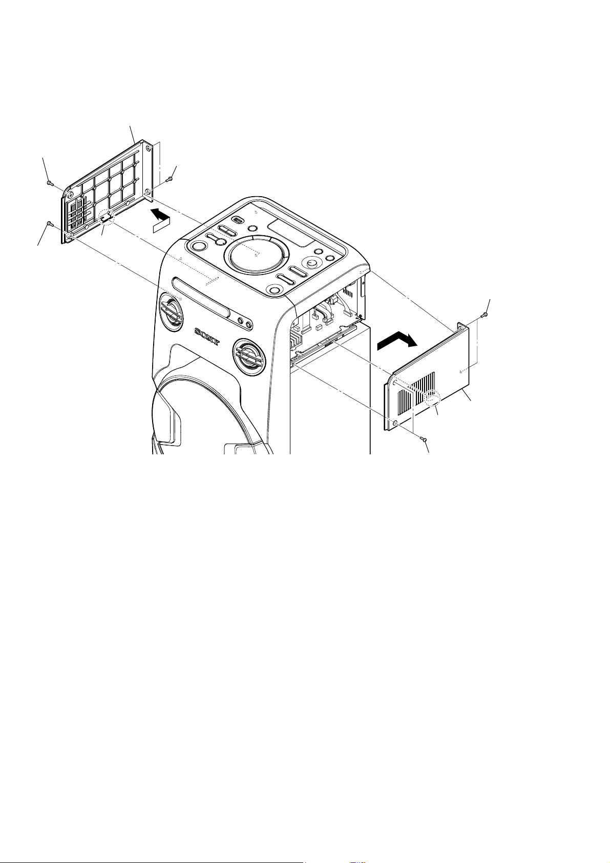
2-2. Left Side Cover, Right Side Cover ................................. 6
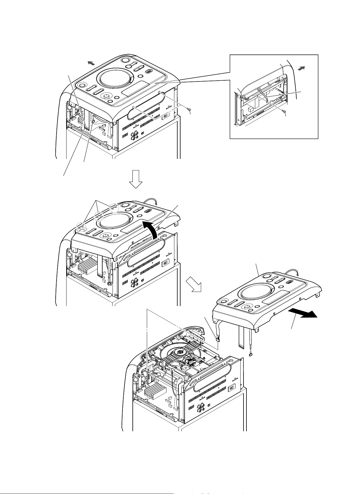
2-3. Top Cover Block ............................................................. 7
2-4. Main Volume Knob, MIC Volume Knob ........................ 8
2-5. CONTROL Board........................................................... 9
2-6. Top Cover Assy, NFC Board .......................................... 9
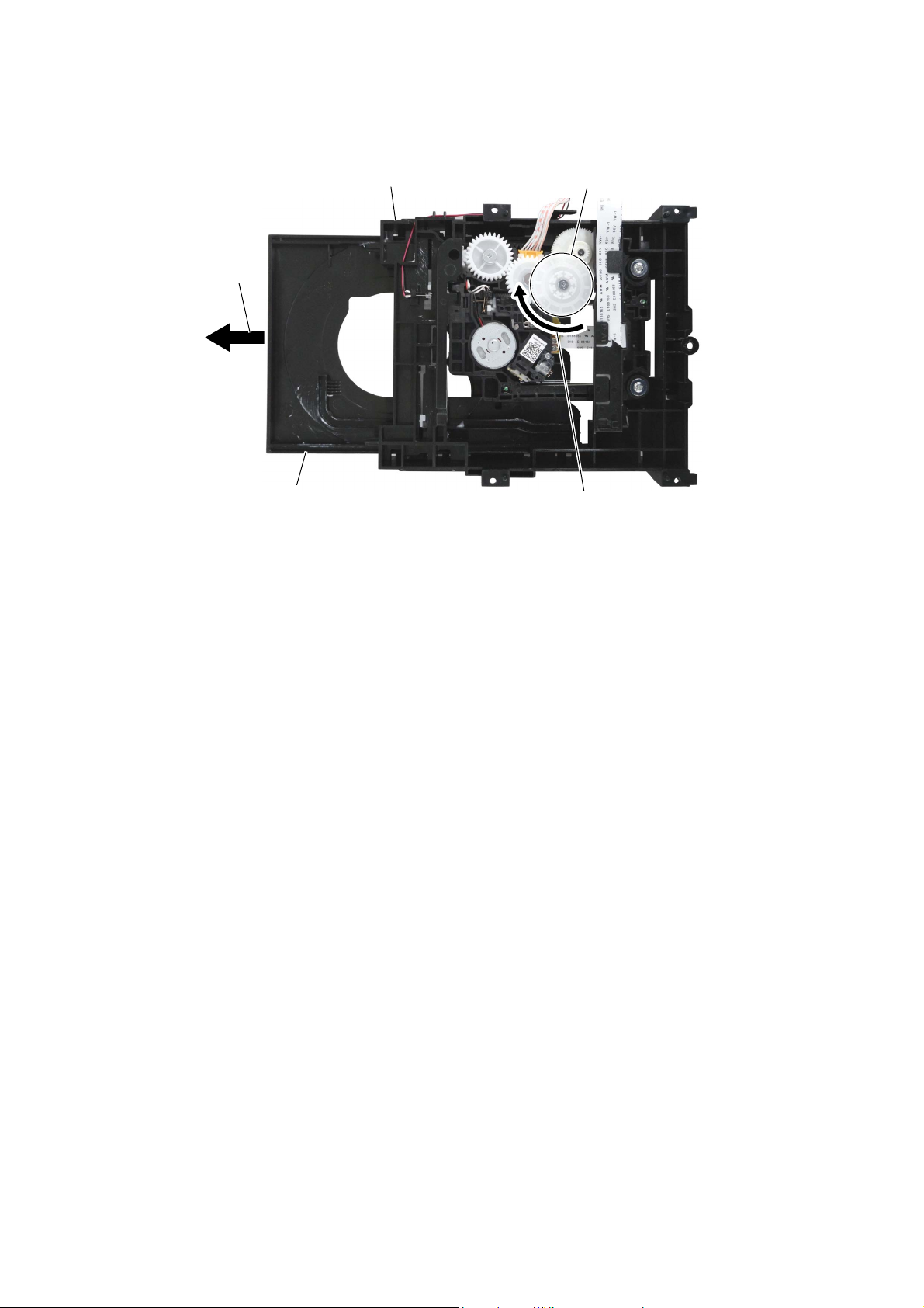
2-7. Loader (CDM1) .............................................................. 10
2-8. BT Board......................................................................... 11
2-9. Chassis Block.................................................................. 12
2-10. Front Panel Block ........................................................... 13
2-11. Tweeter Unit Wire........................................................... 14
2-12. Tweeter Unit (SP2, SP3) ................................................. 15
2-13. LED A Board, LED B Board .......................................... 16
2-14. Woofer Unit (SP1) .......................................................... 17
2-15. Loader Block................................................................... 18
2-16. MAIN Board ................................................................... 19
2-17. PSU Board ...................................................................... 19
3. TEST MODE ............................................................ 20
4. ELECTRICAL CHECKS ...................................... 21
5. DIAGRAMS
5-1. Block Diagram - OVERALL Section -........................... 22
5-2. Block Diagram - POWER SUPPLY Section -................ 23
5-3. Printed Wiring Board - MAIN Board -........................... 25
5-4. Schematic Diagram - MAIN Board (1/9) -..................... 26
5-5. Schematic Diagram - MAIN Board (2/9) -..................... 27
5-6. Schematic Diagram - MAIN Board (3/9) -..................... 28
5-7. Schematic Diagram - MAIN Board (4/9) -..................... 29
5-8. Schematic Diagram - MAIN Board (5/9) -..................... 30
5-9. Schematic Diagram - MAIN Board (6/9) -..................... 31
5-10. Schematic Diagram - MAIN Board (7/9) -..................... 32
5-11. Schematic Diagram - MAIN Board (8/9) -..................... 33
5-12. Schematic Diagram - MAIN Board (9/9) -..................... 34
5-13. Printed Wiring Board - BT Board -................................. 35
5-14. Schematic Diagram - BT Board - ................................... 35
5-15. Printed Wiring Board - NFC Board -............................... 35
5-16. Schematic Diagram - NFC Board - ................................. 35
5-17. Printed Wiring Board - KARAOKE (MIC) Board -....... 36
5-18. Schematic Diagram - KARAOKE (MIC) Board -.......... 36
5-19. Printed Wiring Board - LED A Board - .......................... 37
5-20. Schematic Diagram - LED A Board - ............................. 37
5-21. Printed Wiring Board - LED B Board - .......................... 37
5-22. Schematic Diagram - LED B Board -............................. 37
5-23. Printed Wiring Board - CONTROL Board -................... 38
5-24. Schematic Diagram - CONTROL Board -...................... 39
5-25. Printed Wiring Board - PSU Board - .............................. 40
5-26. Schematic Diagram - PSU Board - ................................. 41
6. EXPLODED VIEWS
6-1. Side Cover Section.......................................................... 47
6-2. Top Cover Section........................................................... 48
6-3. Woofer Unit Section ....................................................... 49
6-4. Front Panel Section......................................................... 50
6-5. Main Section ................................................................... 51
7. ACCESSORIES ........................................................ 52
TABLE OF CONTENTS
NOTES ON HANDLING THE OPTICAL PICK-UP
BLOCK OR BASE UNIT
The laser diode in the optical pick-up block may suffer electro-
static break-down because of the potential difference generated by
the charged electrostatic load, etc. on clothing and the human body.
During repair, pay attention to electrostatic break-down and also
use the procedure in the printed matter which is included in the
repair parts.
The flexible board is easily damaged and should be handled with
care.
NOTES ON LASER DIODE EMISSION CHECK
The laser beam on this model is concentrated so as to be focused
on the disc reflective surface by the objective lens in the optical
pickup block. Therefore, when checking the laser diode emission,
observe from more than 30 cm away from the objective lens.

MHC-V11
4
HOW TO OPEN THE TRAY WHEN POWER SWITCH TURN OFF
Note: Refer to “2. DISASSEMBLY” to remove the loader (CDM1) from the unit.
1Rotate the gear in the
direction of the arrow.
loader (CDM1)
–Bottom view –
gear
2Draw out the tray.
tray

MHC-V11
5
SECTION 2
DISASSEMBLY
• This set can be disassembled in the order shown below.
2-1. DISASSEMBLY FLOW
SET
2-2. LEFT SIDE COVER,
RIGHT SIDE COVER
(Page 6)
2-3. TOP COVER BLOCK
(Page 7)
2-4. MAIN VOLUME KNOB,
MIC VOLUME KNOB
(Page 8)
2-5. CONTROL BOARD
(Page 9)
2-7. LOADER (CDM1)
(Page 10)
2-17. PSU BOARD
(Page 19)
2-8. BT BOARD
(Page 11)
2-9. CHASSIS BLOCK
(Page 12)
2-15. LOADER BLOCK
(Page 18)
2-16. MAIN BOARD
(Page 19)
2-10. FRONT PANEL BLOCK
(Page 13)
2-14. WOOFER UNIT (SP1)
(Page 17)
2-13. LED A BOARD,
LED B BOARD
(Page 16)
2-12. TWEETER UNIT (SP2, SP3)
(Page 15)
2-11. TWEETER UNIT WIRE
(Page 14)
2-6. TOP COVER ASSY,
NFC BOARD
(Page 9)
JIG
When disassembling the unit, use the following
jig for speaker removal.
Part No. Description
J-2501-238-A JIG FOR SPEAKER REMOVAL

MHC-V11
6
Note: Follow the disassembly procedure in the numerical order given.
2-2. LEFT SIDE COVER, RIGHT SIDE COVER
1two screws
4right side cover
3claw
2two screws
4left side cover
3claw
2two screws
1screw
1screw

MHC-V11
7
2-3. TOP COVER BLOCK
2connector (4P)
(XP7)
1FFC (20P)
(XP10)
front side
3two screws 4screw
– Left view –
front side
6three claws
5Lift up the top cover block
in the direction of the arrow.
8connector (5P)
(XP6)
9top cover block
7Remove the top cover
block in the direction
of the arrow.
wire
This side is the
terminal side.

MHC-V11
8
2-4. MAIN VOLUME KNOB, MIC VOLUME KNOB
How to install the volume knob
When installing the volume knob to the rotary encoder, align the directions
of the D-shaped tip of the rotary encoder and the D-shaped notch at the
inner side of the volume knob.
hole
1Push the main volume knob
by a flathead screwdriver.
2main volume knob
flathead
screwdriver
3Insert a flathead screwdriver at both sides of
the MIC volume knob and lift at the same time.
Note 2: When using a flathead screwdriver, work
carefully so that you do not damage the
MIC volume knob and top cover block.
flathead
screwdriver
Note 3: Place soft pieces of cloth between
the MIC volume knob and the top
cover block to avoid damaging
the top cover block.
4MIC volume knob
top cover block
front side
MIC volume knob
main volume knob top cover block
rotary encoder
rotary encoder
Note 1: The MIC volume knob can be removed even without remov-
ing the main volume knob.

MHC-V11
9
2-5. CONTROL BOARD
2-6. TOP COVER ASSY, NFC BOARD
1seven screws
top cover block
1seven screws
1four screws
rear side
2Lift up the CONTROL board block
in the direction of the arrow.
3connector (2P)
(XP2)
4FFC (20P)
(XP1)
5CONTROL board
top side
This side is
the terminal side.
rear side
5NFC board
3top cover assy
1two claws 2Peel the NFC board block
off of the adhesive sheet.
4connector (2P)
(XP15)
top side
Note: When replacing the NFC board, be sure to replace the BT board
and the NFC board simultaneously. The NFC board cannot re-
place with single. Among the repair parts, the BT board and the
NFC board is supplied as one unit.

MHC-V11
10
2-7. LOADER (CDM1)
WireVHWWLQJ
5two screws
5two screws
1cushion
6loader (CDM1)
three hooks
–5LJKWYLHZ–
front side
3connector (6P)
(XP5)
2FFC (24P)
(XP4)
4connector (2P)
(XP6)
cushion
MAIN board
loader (CDM1)
The opposite side is
the terminal side.

MHC-V11
11
2-8. BT BOARD
2two screws
5screw
1FFC (24P)
(XP35)
3handle block
4FFC (24P)
(XP1)
6handle
5screw
A
A
rear side
two holes
two bosses
7BT board
Note 2: When installing the BT
board, align the two holes
and the two bosses.
The opposite side is
the terminal side.
This side is the terminal side.
Note 1: When replacing the BT board, be sure to replace the BT board
and the NFC board simultaneously. The BT board cannot re-
place with single. Among the repair parts, the BT board and
the NFC board is supplied as one unit.

MHC-V11
12
2-9. CHASSIS BLOCK
A
BC
A
B
C
2screw
3three screws
3screw
front side
3screw
4rib
4rib
8chassis block
7connector (4P)
(XP9)
6connector (4P)
(XP13)
5connector (2P)
(XP14)
1connector (7P)
(XP11)
wire

MHC-V11
13
2-10. FRONT PANEL BLOCK
speaker cabinet
4 All bosses are removed while
moving jig in the direction of
the arrow, and front panel block
is removed.
4 All bosses are removed while
moving jig in the direction of
the arrow, and front panel block
is removed.
2 Insert a flathead screwdriver
in two notches at bottom of
the unit, and lift the front
panel block a little.
total eleven bosses
5 front panel block
Note 2: When installing the front panel block,
remove the used bond and use a new
bond to fix the front panel block.
3Insert the jig into the space and
slowly remove the front panel block.
Note 1: When using a jig, please work
carefully so as not to damage
the front panel block and
speaker cabinet.
1three
screws
1screw
1screw
bottom side 3Insert the jig into the space and
slowly remove the front panel block.
Note 1: When using a jig, please work
carefully so as not to damage
the front panel block and
speaker cabinet.

MHC-V11
14
2-11. TWEETER UNIT WIRE
protrusion
protrusion
1Push the protrusion, and remove
the terminal (narrow side).
1Push the protrusion, and remove
the terminal (wide side).
protrusion
protrusion
short wire long wire
1Push the protrusion, and remove
the terminal (wide side).
1Push the protrusion, and remove
the terminal (narrow side).
to
tweeter unit
(R-ch)
to
tweeter unit
(L-ch)
7ZHHWHUXQLWZLUHVHWWLQJ
front side
front panel block
tweeter unit (L-ch)
(SP2)
tweeter unit (R-ch)
(SP3)
2tweeter unit wire
short wire
long wire

MHC-V11
15
2-12. TWEETER UNIT (SP2, SP3)
front side
front panel block
1two screws
2bracket
3tweeter unit (L-ch)
(SP2)
1two screws
2bracket
3tweeter unit (R-ch)
(SP3)
– Front panel block rear view –
arrow
Install so that the terminal (narrow side) of the tweeter
unit aligns with the direction of the arrow.
,nVtallation Girection Ior tKe tweeter Xnit 5cK 63
,nVtallation Girection Ior tKe tweeter Xnit /cK 63
– Front panel block rear view –
arrow
Install so that the terminal (wide side) of the tweeter
unit aligns with the direction of the arrow.

MHC-V11
16
2-13. LED A BOARD, LED B BOARD
LED B board LED A board
WireVeWWiQJ
white line
white line
front side
front panel block
groove
groove
groove
groove
1Draw the cable out
of the groove.
1Draw the cable out
of the groove.
2screw
2screw
3Remove the LED B board
block in the direction of
the arrow.
3Remove the LED A board block
in the direction of the arrow.
4connector (2P)
(XP3)
4connector (2P)
(XP4)
5cushion
5cushion
6LED B
board
6LED A
board
groove
LED A board
LED B board
groove
groove
groove
top side
–)rRQWSDQeOEORFNreDrYieZ–

MHC-V11
17
2-14. WOOFER UNIT (SP1)
speaker cabinet block
narrow side
wide side
terminal position
woofer unit
(SP1)
top side
– Speaker cabinet block front view –
,QVWDOODWLRQGLUHFWLRQIRUWKHZRRIHUXQLW63
front side
1three screws
1three screws
2Pull out the woofer unit block
in the direction of the arrow.
4woofer unit
(SP1)
Note: When installing the woofer unit (SP1),
make the position of terminals as shown
in the figure below.
protrusion
protrusion
3Push the protrusion,
and remove the
terminal (wide side).
3Push the protrusion, and remove the
terminal (narrow side).

MHC-V11
18
2-15. LOADER BLOCK
A
A
B
C
C
B
WireVeWWiQJ
three hooks
–5iJKWYieZ–
front side
loader (CDM1)
MAIN board
5three screws
2connector (6P)
(XP5)
1FFC (24P)
(XP4)
3connector (2P)
(XP6)
4three screws
7loader block 6rib
6rib
front side
chassis block
The opposite side is
the terminal side.

MHC-V11
19
2-16. MAIN BOARD
2-17. PSU BOARD
front side
chassis block
2screw
1connector (9P)
(XP2)
4MAIN board
3screw
3screw
3screw
3screw
A
A
front side
chassis block
1connector (9P)
(XP2)
3two screws
2AC inlet
connector (2P)
(CN501)
3two screws
rib
hole
4PSU board
Note: When installing the PSU board,
align the hole and groove with
the two ribs.
rib
groove

MHC-V11
20
SECTION 3
TEST MODE
SOFTWARE VERSION DISPLAY
It can confirm the software version.
Procedure:
1. Press the [1] button to turn the power on.
2. Press the [FUNCTION] button to select the CD function.
3. Press the [Z] button to open the disc tray.
4. Press the button on the remote commander as following order,
the software version is displayed on the fluorescent indicator
tube.
[CLEAR] →[B] →[BACK]
(Displayed values in the following figure are example)
Screen display
MCU version
Model No.
(this model is “4”) Model ID
(Destination)
BT version
MPEG version
Model ID (Destination)
Model ID (Destination) Display
US and Canadian models (UC2) 0
5. The software version display disappears in about 5 seconds,
and it return to the display of the normal mode.
FACTORY RESET
It can reset all MPEG settings and clear the Bluetooth linked list.
Execute this mode when returning the this unit to the customer.
Procedure:
1. Press the [1] button to turn the power on.
2. Press two buttons of the [x] and [–] simultaneously for 5
seconds.
3. The message “RESET” is displayed on the fluorescent indica-
tor tube, and then reboot the system.
Screen display
Other manuals for MHC-V11
1
Table of contents
Other Sony Stereo System manuals

Sony
Sony HCD-GNX60 User manual

Sony
Sony MHC-V800 User manual

Sony
Sony CMT-NEZ30 User manual

Sony
Sony DHC-MD373 User manual

Sony
Sony HCD-VZ0 User manual

Sony
Sony MHC-GN660 User manual

Sony
Sony MHC-GX8000 - Mini Stereo System User manual

Sony
Sony ZS-D50 Operating Instructions (primary... User manual

Sony
Sony HCD-RG444 User manual

Sony
Sony MAP-S1 User manual

Sony
Sony SRS-X88 User manual

Sony
Sony HCD-SPZ90DAB User manual

Sony
Sony MHC-RV900D User manual

Sony
Sony HCD-MC3AV User manual

Sony
Sony MHC-V50 User manual

Sony
Sony MHC-GRX10AV User manual

Sony
Sony HCD-RG11 User manual

Sony
Sony CMTBX5BT - CMT Micro System User manual

Sony
Sony HCD-VP11 User manual

Sony
Sony HCD-RXD6AV User manual