Sony HCD-BX7 User manual

1
HCD-BX7/DX7/DX7J
SERVICE MANUAL
HCD-BX7/DX7/DX7Jisthetuner,deck,CDand
amplifier section in MHC-BX7/DX7/DX7J.
SPECIFICATIONS
COMPACT DISC DECK RECEIVER
— Continued on next page —
Model Name Using Similar Mechanism NEW
CD Mechanism Type CDM58-K2BD38
Base Unit Type BU-K2BD38
Optical Pick-up Type KSS-213DP
Model Name Using Similar Mechanism NEW
Tape Transport Mechanism Type TCM-230MWR11
CD
SECTION
TAPE DECK
SECTION
Photo: HCD-DX7
US Model
Canadian Model
AEP Model
UK Model
HCD-BX7
E Model
HCD-DX7/DX7J
Australian Model
HCD-DX7

2
SAFETY CHECK-OUT
(US model only)
After correcting the original service problem, perform the
following safety checks before releasing the set to the customer:
Check the antenna terminals, metal trim, “metallized” knobs, screws,
and all other exposed metal parts forAC leakage. Check leakage as
described below.
LEAKAGE
TheAC leakage from any exposed metal part to earth ground and
from all exposed metal parts to any exposed metal part having a
return to chassis, must not exceed 0.5 mA (500 microampers).
Leakage current can be measured by any one of three methods.
1. A commercial leakage tester, such as the Simpson 229 or RCA
WT-540A. Follow the manufacturers’instructions to use these
instruments.
2. A battery-operated AC milliammeter. The Data Precision 245
digital multimeter is suitable for this job.
3. Measuring the voltage drop across a resistor by means of a
VOM or battery-operatedAC voltmeter. The “limit” indication
is 0.75 V, so analog meters must have an accurate low-voltage
scale. The Simpson 250 and Sanwa SH-63Trd are examples of
a passive VOM that is suitable. Nearly all battery operated
digital multimeters that have a 2V AC range are suitable. (See
Fig. A)
Fig. A. Using an AC voltmeter to check AC leakage.
0.15µF
To Exposed Metal
Parts on Set
1.5kΩ
AC
voltmeter
(0.75V)
Earth Ground

3
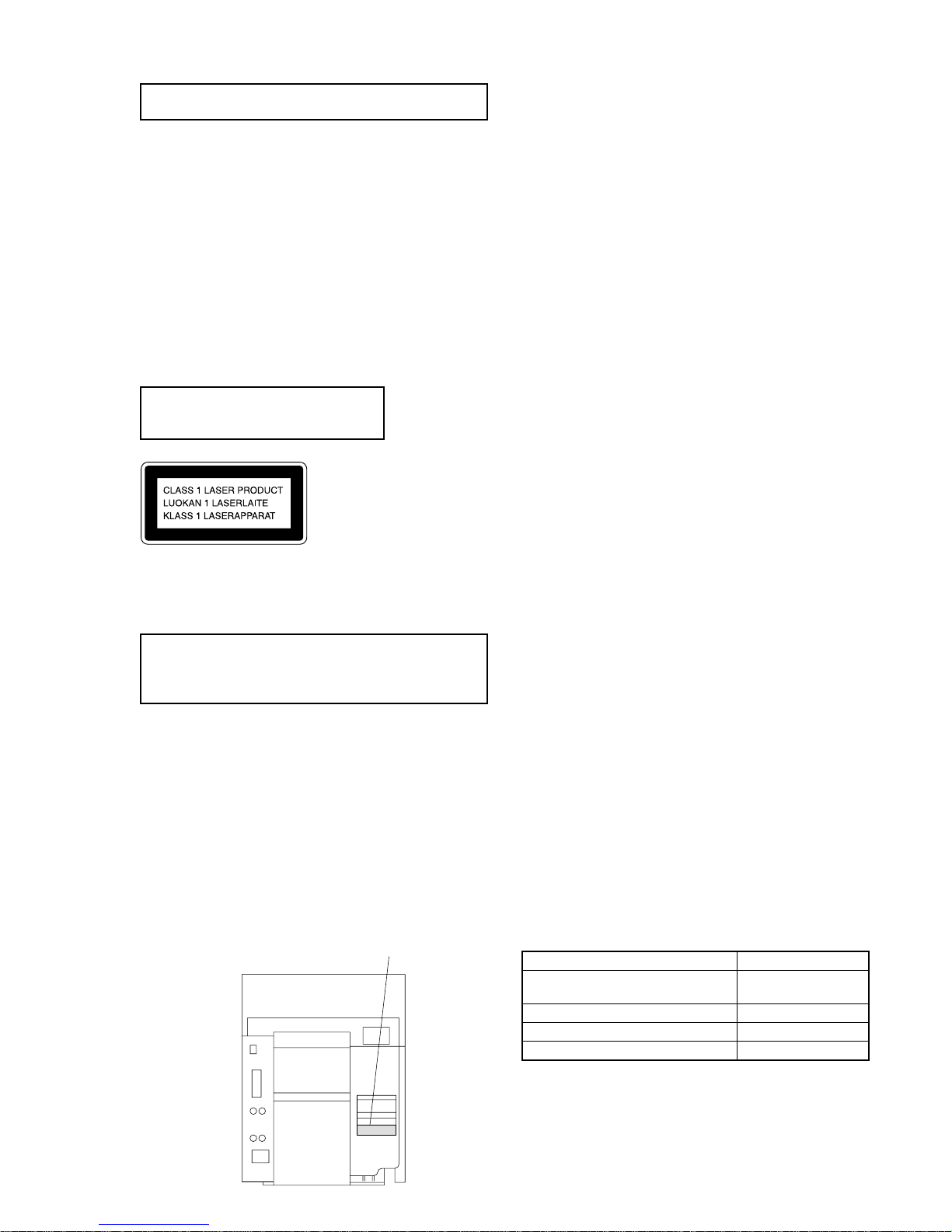
This appliance is classified as a CLASS 1 LASER product. The
CLASS 1 LASER PRODUCT MARKING is located on the rear
exterior.
Laser component in this product is capable
of emitting radiation exceeding the limit for
Class 1.
CAUTION
Use of controls or adjustments or performance of procedures
otherthanthosespecifiedherein may result in hazardous radiation
exposure.
Notes on chip component replacement
•Never reuse a disconnected chip component.
•Notice that the minus side of a tantalum capacitor may be
damaged by heat.
Flexible Circuit Board Repairing
•Keep the temperature of soldering iron around 270˚C
during repairing.
•Do not touch the soldering iron on the same conductor of the
circuit board (within 3 times).
•Be careful not to apply force on the conductor when soldering
or unsoldering.
NOTES ON HANDLING THE OPTICAL PICK-UP
BLOCK OR BASE UNIT
The laser diode in the optical pick-up block may suffer electrostatic
break-down because of the potential difference generated by the
charged electrostatic load, etc. on clothing and the human body.
During repair, pay attention to electrostatic break-down and also
use the procedure in the printed matter which is included in the
repair parts.
The flexible board is easily damaged and should be handled with
care.
NOTES ON LASER DIODE EMISSION CHECK
The laser beam on this model is concentrated so as to be focused on
the disc reflective surface by the objective lens in the optical pick-
up block. Therefore, when checking the laser diode emission,
observe from more than 30 cm away from the objective lens.
MODEL IDENTIFICATION
— BACK PANEL —
TABLE OF CONTENTS
1. SERVICE NOTE ······························································· 4
2. GENERAL ·········································································· 5
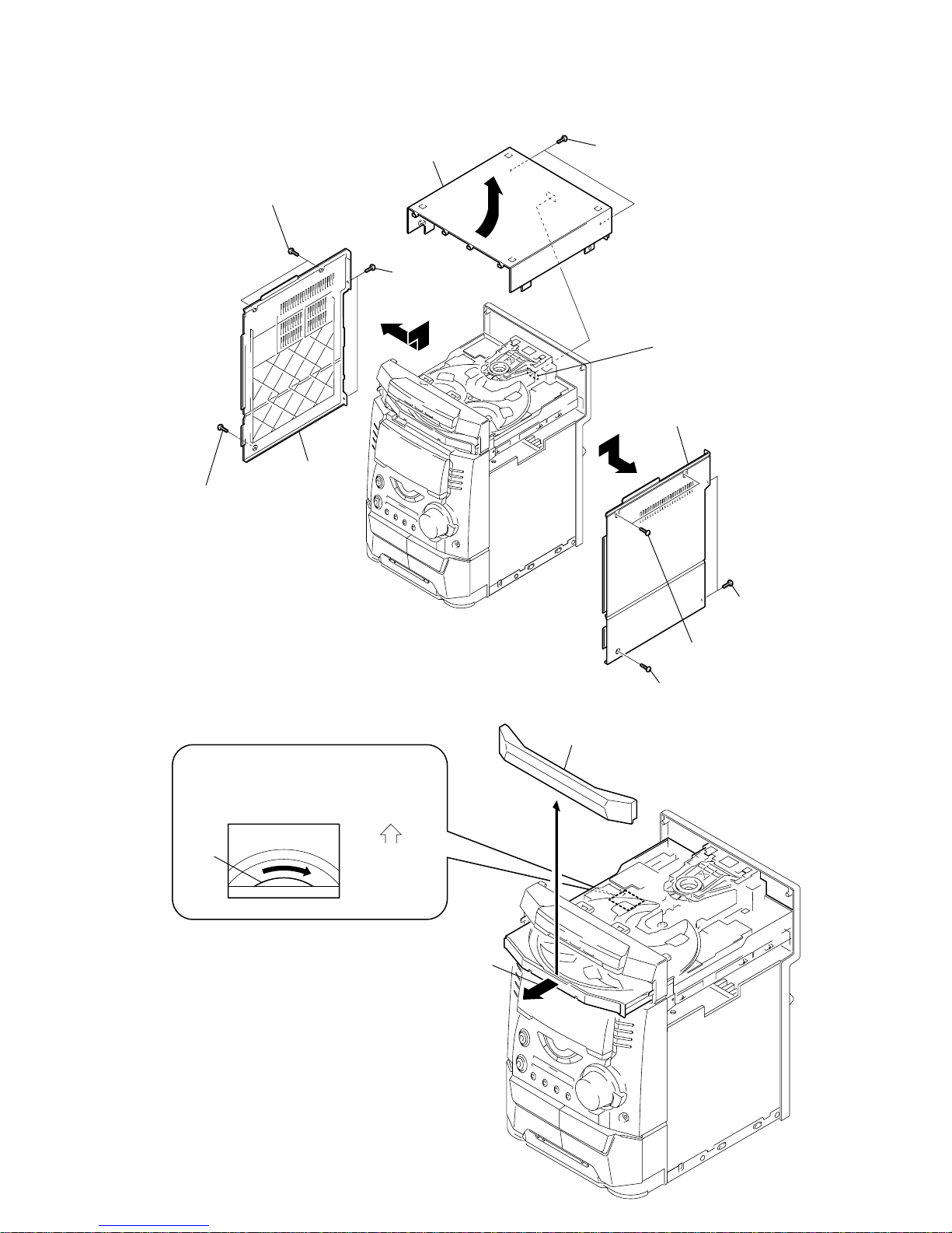
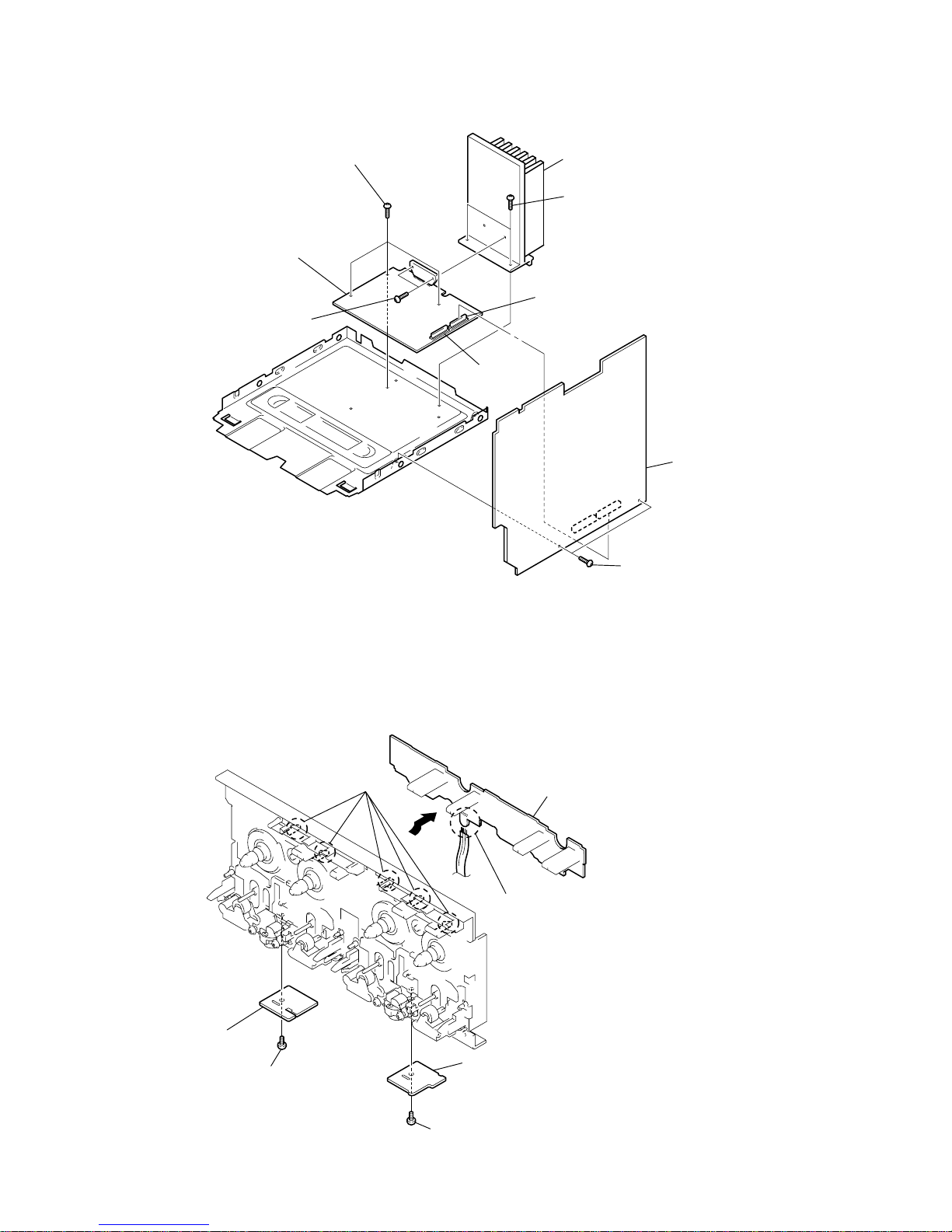
3. DISASSEMBLY ································································ 7
4. TEST MODE···································································· 12
5. MECHANICAL ADJUSTMENTS ····························· 16
6. ELECTRICAL ADJUSTMENTS ······························· 16
7. DIAGRAMS
7-1. Circuit Board Location ····················································· 21
7-2. Block Diagrams ································································ 22
7-3. Printed Wiring Board –BD Section – ······························ 24
7-4. Schematic Diagram –BD Section –································· 25
7-5. Printed Wiring Board –Main Section – ··························· 26
7-6. Schematic Diagram –Main (1/3) Section – ····················· 27
7-7. Schematic Diagram –Main (2/3) Section – ····················· 28
7-8. Schematic Diagram –Main (3/3) Section – ····················· 29
7-9. Printed Wiring Board –Power AMP Section –
(BX7 model)····································································· 30
7-10. Schematic Diagram –Power AMP Section –
(BX7 model)····································································· 31
7-11. Printed Wiring Board –Power AMP Section –
(DX7, DX7J model) ························································· 32
7-12. Schematic Diagram –Power AMP Section –
(DX7, DX7J model) ························································· 33
7-13. Printed Wiring Board –Panel Section – ··························· 34
7-14. Schematic Diagram –Panel Section – ····························· 35
7-15. Printed Wiring Board –Leaf SW Section – ···················· 36
7-16. Schematic Diagram –Leaf SW Section – ························ 37
7-17. Printed Wiring Board –Driver Section – ························· 38
7-18. Schematic Diagram –Driver Section – ···························· 39
7-19. Printed Wiring Board –Trans Section –
(BX7 model)····································································· 40
7-20. Schematic Diagram –Trans Section –
(BX7 model)····································································· 41
7-21. Printed Wiring Board –Trans Section –
(DX7, DX7J model) ························································· 42
7-22. Schematic Diagram –Trans Section –
(DX7, DX7J model) ························································· 43
7-23. IC Pin Function Description············································· 44
7-24. IC Block Diagrams ··························································· 46
8. EXPLODED VIEWS
8-1. Main Section····································································· 49
8-2. Panel Section ···································································· 50
8-3. Main Board Section·························································· 51
8-4. Tape Mechanism Section·················································· 52
8-5. CD Mechanism Section···················································· 53
9. ELECTRICAL PARTS LIST ······································· 54
PARTS No.
•Abbreviation
CND : Canadian model
AUS : Australian model
G : German model
EA :Saudi Arabia model
MY : Malaysia model
SP : Singapore model
TH :Thai model
KR : Korea model
MX : Mexican model
AR : Argentina model
E2 : Central and
South AMERICA
E3 : Middle and Near East
MODEL
AED, AEP, CIS, UK, G, AUS,
KR, MX, TH models
AR, E, EA, SP, TW, MY models
US, CND models
DX7J model
PARTS No.
4-225-040-1s
4-225-040-2s
4-225-040-3s
4-228-592-3s

4
SECTION 1
SERVICE NOTE
Screw hole
Attach the panel board with
six screws (
+BVTP 2.6
×
8
)
after the board is removed once.
Do not tighten the screws excessively.
1
Cut the eleven melted-connection points with a cutting plier.
Note for installing the panel board
2
Panel board
Hot melt

5
SECTION 2
GENERAL
1DISC SKIP EX-CHANGE button
2DISC 1 button and indicator
3DISC 2 button and indicator
4DISC 3 button and indicator
5ZOPEN/CLOSE button
6EDIT, TUNER MOMERY button
7PLAY MODE, STEREO/MONO button
8REPEAT, DOLBY NR button
9DIRECTION knob (EXCEPT AEP, G, UK, CIS)
DIRECTION, PTY knob (AEP, G, UK, CIS model)
q; SURROUND button
qa VOLUME knob
qs PHONES jack
qd ENTER button
qf REC PAUSE/START button and indicator
qg CD SYNC HI-DUB button
qh LOOP button (BX7 model)
LOOP, KARAOKE PON button (DX7, DX7J model)
qj MIC jack (DX7, DX7J model)
qk MIC LEVEL knob (DX7, DX7J model)
ql V-GROOVE button and indicator
w; CURSOL button and indicator
wa GROOVE button
ws EQ EDIT button
wd SPECTRUM button
wf DISPLAY button
wg ?/1 button and indicator
wh TUNER/BAND button
wj MD (VIDEO) button
wk Ybutton
wl >+ button
e; Xbutton
ea – .button
es xbutton
ed TAPE A/B button
ef CD button
eg Function indicator
Photo: HCD-BX7
1234 5
6
7
8
qa
qs
qdqfqgqh
w;
ws
ed
ef wh
wj
wk
wl
e;
ea
9
q;
wa
ql
wd
wf
wg
es
qk
qj
eg

6
6
Step 1: Hooking up the system
(continued)
To attach the front speaker pads
Attach the supplied front speaker pads to the
bottom of the speakers to stabilize the
speakers and prevent them from slipping.
Positioning the speakers
Before you connect them, determine the best
location for your speakers.
1Place the front speakers at an angle
of 45 degrees from your listening
position.
2Place the surround speakers facing
each other at about 60 to 90 cm
above your listening position.
E
e
eE
Front
speaker
(L)
Front
speaker
(R)
Surround
speaker
(L)
Surround
speaker
(R)
45º
Surround
speaker
60 to 90 cm
Inserting two size AA (R6)
batteries into the remote
Tip
With normal use, the batteries should last for about
six months. When the remote no longer operates
the system, replace both batteries with new ones.
Note
If you do not use the remote for a long period of
time, remove the batteries to avoid possible damage
from battery leakage.
When carrying this system
Do the following to protect the CD
mechanism.
1Make sure that all discs are removed from
the unit.
2Hold down CD and then press ?/1 so that
“LOCK”appears in the display.
3Unplug the AC power cord.
7
1
Press CLOCK/TIMER SET.
The hour indication flashes.
2
Press .or >repeatedly to set
the hour.
3
Press ENTER.
The minute indication flashes.
4
Press .or >repeatedly to set
the minute.
5
Press ENTER.
The clock starts working.
Tip
If you’ve made a mistake, start over from step 1.
To change the time
The previous explanation shows you how to set the
time while the power is off. To change the time
while the power is on, do the following:
1Press CLOCK/TIMER SET.
2Press .or >repeatedly to select
SET CLOCK.
3Press ENTER.
4Perform steps 2 through 5 above.
Note
The clock settings are canceled when you disconnect
the power cord or if a power failure occurs.
Step 2: Setting the
t
ime
Y
ou must set the time before using the timer
f
unctions.
T
he clock is on a 24-hour system for the
E
uropean model and a 12-hour system for
o
ther models.
T
he 24-hour system model is used for
i
llustration purposes.
mM
.>
YX x
x
NX
1
3,5
2,4
This section is extracted from
instruction manual.

7
SECTION 3
DISASSEMBY
Note : Follow the disassembly procedure in the numerical order given.
Side panel R
Claw
4
q;
8
Upper case (Top)
Side panel L
5
Two screws (Case)
7
Two screws
(+BVTP 3
×
10)
1
Two screws (Case)
9
Two screws (+BVTP 3
×
10)
3
Two screws
(+BVTP 3
×
10)
6
Screw (Case)
2
Screw (Case)
2
Pull-out the disc tray.
1
Turn the pulley to the direction of arrow.
pulley
Loading panel assy
Front panel side
CD mechanism deck (CDM58)
3
3-1. UPPER CASE (TOP)
3-2. LOADING PANEL ASSY

8
7
0
CD mechanism deck (CDM58)
Front panel section
3
Connector (CN2)
8
Connector (CN201)
9
Connector (CN202)
2
Connector (CN1)
Connector
(CN601)
1
Flat type wire (CN304)
6
Three screws (+BVTT 3
×
6)
5
Screw (+BVTP 3
×
10)
4
Screw (+BVTP 3
×
10)
6
Tape mechanism deck
5
Five screws (+BVTP 2.6
×
8)
1
Screw (+BVTP 2.6
×
8
)
2
Bracket (Heart cam R)
4
Bracket (Heart cam L)
3
Screw (+BVTP 2.6
×
8)
3-3. FRONT PANEL SECTION
3-4. TAPE MECHANISM DECK

9
q;
Cut the eleven melted-connection points with a cutting plier.
Note: When attching the panel board,
refer to "Service Note" on page 4.
qs
Panel board
9
CD Switch boar
d
VCD Switch board
1
Knob (Volume)
6
5
FR knob
4
Bracket (FR)
qa
Five claws
8
Three claws
7
Two
screws
(+BVTP 2.6
×
8)
3
Two bosses & four pins
2
Two screws
(+BVTP 2.6
×
8)
qs
Two screws
(+BVTT 4
×
8)
3
Two screws
(+BVTP 3
×
8)
6
Six screws
(+BVTP 3
×
10
)
5
Two screws
(+BVTP 3
×
10)
8
Panel, back
qa
Two screws (+BVTT 4
×
8)
qf
Trans board
4
Sub-trans
board
qd
Trans
1
Connector (CN975)
9
Connector (CN975)
0
Connector (CN977)
7
Connector (CN891)
2
Connector (CN974)
3-5. PANEL BOARD
3-6. SUB-TRANS BOARD ANDTRANS BOARD

10
4
Three screws (+BVTP 3
×
8)
6
Two screws (+BVTP 3
×
8)
7
Heat sink
3
Two screws (+BVTP 3
×
16)
1
Two screws (+BVTP 3
×
8
)
2
Main board
Connector(CN502)
Connector
(CN503)
5Power
AMP board
6
Screw (+PS 2.6
×
5)
3
Screw (+PS 2.6
×
5)
2Leaf
SW board
1
Five claws
4
Head (A) board
5
Head (B) board
6
Remove the four solderings.
3-7. MAIN BOARD AND AMP BOARD
3-8. LEAF SW BOARD, HEAD (A) BOARD AND HEAD (B) BOARD

11
Base unit
3
2
Four screws (+PTPWH 2.6)
4
Two insulators
5
Two insulators
1
Flat type wire (CN101)
4
Three
screws (+BVTP 2.6
×
8)
9
Screw (+PTPWH 2.6
×
8)
q;
Tray
1
Screw (+BVTP 2.6
×
8)
qa
Screw (+BVTP 2.6
×
8)
7
Flat type wire (CN721)
6
Motor board
qs
Address Sensor board
8
Connector(CN722)
2
Driver board
3
Connector (CN701)
5
Remove the two solderings of motor.
3-9. BASE UNIT
3-10. DRIVER BOARD, MOTOR BOARD AND ADDRESS SENSOR BOARD

12
SECTION 4
TEST MODE
[MC Cold Reset]
• The cold reset clears all data including preset data stored in the
RAM to initial conditions. Execute this mode when returning
the set to the customer.
Procedure:
1. Press three buttons x, ENTER , and ?/1simulta-neously.
2. The fluorescent indicator tube displays “COLD RESET” and
the set is reset.
[CD Ship Mode]
• This mode moves the pickup to the position durable to vibra-
tion. Use this mode when returning the set to the customer after
repair.
Procedure:
1. Press ?/1button to turn the set ON.
2. Press CD button and ?/1button simultaneously.
3. After the "STANDBY" display blinks six times, a message
“LOCK” is displayed on the fluorescent indicator tube, and the
CD ship mode is set.
[MC Hot Reset]
• This mode resets the set with the preset data kept stored in the
memory. The hot reset mode functions same as if the power
cord is plugged in and out.
Procedure:
1. Press three buttons x, ENTER , and DISC 1 simultaneously.
2. The fluorescent indicator tube becomes blank instantaneously,
and the set is reset.
[CD Service Mode]
• This mode can run the CD sled motor freely. Use this mode, for
instance, when cleaning the pickup.
Procedure:
1. Press ?/1button to turn the set ON.
2. Select the function “CD”.
3. Press three buttons x, ENTER , and OPEN/CLOSE simul-
taneously.
4. The CD service mode is selected.
5. With the CD in stop status, turn the shuttle knob clockwise to
move the pickup to outside track, or turn the shuttle knob
counter-clockwise to inside track.
6. To exit from this mode, perform as follows:
1) Move the pickup to the most inside track.
2) Press three buttons in the same manner as step 2.
Note: • Always move the pickup to most inside track when exiting from
this mode. Otherwise, a disc will not be unloaded.
• Do not run the sled motor excessively, otherwise the gear can be
chipped.
[VACS ON/OFF Mode]
• This mode is used to switch ON and OFF the VACS (Variable
Attenuation Control System).
Procedure:
Press the ENTER and SPECTRUM buttons simultaneously. The
message “VACS OFF” or “VACS ON” appears.
[Change-over of MW Tuner Step between 9 kHz and
10 kHz]
• A step of MW channels can be changed over between 9 kHz
and 10 kHz.
Procedure:
1. Press ?/1button to turn the set ON.
2. Select the function “TUNER”, and press TUNER/BAND
button to select the BAND “MW”.
3. Press ?/1button to turn the set OFF.
4. Press ENTER and ?/1buttonssimultaneously, and thedisplay
of fluorescent indicator tube changes to “MW 9 k STEP” or
“MW 10 k STEP”, and thus the channel step is changed over.
[GCTest Mode]
• This mode is used to check the software version, FL tube, LED,
keyboard and VACS.
Procedure:
1. Press threebuttons x, ENTER ,and DISC 2 simultaneously.
2. LEDs and fluorescent indicator tube are all turned on.
3. When you want to enter the software version display mode,
press DISC 1 . The model number and destination are displayed.
4. Each time DISC 1 is pressed, the display changes starting
from MC version, GC version, VC version, CD version, CM
version, ST version, TC version, TA version, TM version and
BR version in this order, and returns to the model number and
destination display.
5. When DISC 3 is pressed while the version numbers are being
displayed except model number and destination, year, month
and day of the software creation appear. When DISC 3 is
pressedagain,thedisplayreturns to the software versiondisplay.
When DISC 1 is pressed while year, month and day of the
software creation are being displayed, the year, month and day
of creation of the software versions are displayed in the same
order of version display.
6. Press DISC 2 button, and the key check mode is activated.
7. In the key check mode, the fluorescent indicator tube displays
“KEY0VOL0”. Each time a button is pressed, “KEY” value
increases. However, once a button is pressed, it is no longer
taken into account.
“VOL” value increases like 1, 2, 3 ... if rotating VOLUME
knob in “+” direction, or it decreases like 0, 9, 8 ... if rotating in
“–” direction.
8. Also when DISC 3 is pressed after lighting of all LEDs and FL
tubes, value of VACS appears.
9. To exit from this mode, press three buttons in the same manner
as step 1, or disconnect the power cord.

13
[MCTest Mode]
• This mode is used to check operations of the respective sections
of Amplifier, Tuner, CD and Tape.
Procedure:
1. Press the ?/1button to turn on the set.
2. Press the three buttons of x, ENTER and DISC 3
simultaneously.
3. A message “TEST MODE” appears on the FL display tube.
4 When f(CURSOR UP) button is pressed, GEQ increases to
its maximum and a message “GEQ ALL MA” appears.
5. When F(CURSORDOWN) button is pressed, GEQ decreases
to its minimum and a message “GEQ ALL M1” appears.
6. When g(CURSOR LEFT) or G(CURSOR RIGHT) button
is pressed, GEQ is set to flat and a message “GEQ FLAT”
appears.
7. When the VOLUME control knob is turned clockwise even
slightly, the sound volume increases to its maximum and a
message “VOLUME MAX” appears for two seconds, then the
display returns to the original display.
8. When theVOLUME control knob is turned counter-clockwise
even slightly, the sound volume decreases to its minimum and
a message “VOLUME MIN” appears for two seconds, then
the display returns to the original display.
9. In the test mode, the default-preset channel is called even when
the TUNER is selected and an attempt is made to call the preset
channelthathasbeenstoredinmemory, by operating the Shuttle
knob. (It means that the memory is cleared.)
10. When CD is selected and the EDIT button is pressed, the disc
that is being chucked at this moment becomes the default
setting. It means that the default disc only is accessed when
any other discs are selected even though the display indication
changes accordingly. At the same time, the DISC SKIP EX-
CHANGE and OPEN/CLOSE cannot be accepted. (It means
that the tray motor and the turntable motor are disabled of their
operation.)
11. When a tape is inserted in Deck B and recording is started, the
input source function selects VIDEO automatically.
12. When xbutton is pressed to stop recording, the Tape (Deck)
B is selected and tape is rewound using the Shuttle knob, tape
is rewound, tape is stops at around the record-starting position
and playback of the recorded portion of the tape is started. If
PAUSE is inserted even once during recording, tape is rewound
to the position around the PAUSE position and is played back.
13. When the CD SYNC HI-DUB Button ispress during playback
of Deck B, either normal speed or high speed can be selected
by this button.
14. Select the desired loop by pressing the PLAY MODE button.
Insert a test tapeAMS-110A or AMS-RO to DeckA.
15. Press the SPECTRUM button to enter theAMS test mode.
16. After a tape is rewound first, the FF AMS is checked, and the
mechanism is shut off after detecting the AMS signal twice.
17. Then the REWAMS is checked and the mechanism is shut off
after detecting the AMS signal twice.
18. When the check is complete, a message of either OK or NG
appears.
19. When you want to exit this mode, press the ?/1button twice.
The cold reset is enforced at the same time.

14
[Aging Mode]
This mode can be used for operation check of CD section and tape deck section.
• If an error occurred:
The aging operation stops and display status.
• If no error occurs:
The aging operation continues repeatedly.
1. Operating method ofAging Mode
Turn on the main power and select “CD” of the function.
1) Set a disc in DISC1 tray. Select ALL DISC CONTINUE, and REPEAT OFF.
2) Load the tapes recording use into the decks A and B respectively.
3) Press three buttons x, ENTER , and
DISC SKIP/EX-CHANGE simultaneously.
4) Aging operations of CD and tape are started at the same time.
5) To exit the aging mode, perform [MC Cold Reset].
3. Aging Mode in CD section
1) Display state
• No error occurs
Note:
[*][*][*][*] : Number of aging operations
Error display
E** s## $$ %%
12 3 4 5
• When the buttons x , ENTER and DISC 1 are pressed simultaneously, number of time of the mechanism error and the NO DISC error
can be checked.
Display: EMC**EDC** **: Number of times of error (Maximum three times)
EMC: Mechanism error
EDC: NO DISC error
• When aging operation is complete, be sure to perform the MC Cold Reset to reset the error history.
D: No disc error
01: FOCUS ERROR
02: GFS ERROR
03: SETUP ERROR
01: NO DISC judgment without chucking retry
02: NO DISC judgment after chucking retry
Status at the time of NO DISC judgment
(High order digits only)
1: STOP
2: SETUP
3: TOC READ
4: ACCESS
5: PLAY BACK
6: PAUSE
7: MANUAL SEARCH (PLAY)
8: MANUAL SEARCH (PAUSE)
AGING[*][*][*][*]
1**
2s
3##
4$$
5%%
M: Mechanism error
Don’t care
High order digits only
D: Stopped during closing due to problems other than mechanism.
E: Stopped during opening due to problems other than mechanism.
C: Stopped during chucking due to problems other than mechanism.
F: Stopped during EX-opening due to problems other than mechanism.
Emergency related errors (High order digits only)
1: Stopped during chuck-up
2: Stopped during chuck-down
3: Time out by EX-OPEN
5: Time out by EX-CLOSE
The error No. 00 indicates the newest error. As the error No. increases, it means the older error.
When you want to retrieve the error history, press the PLAY MODE button in the case of mechanism error.
Or press the REPEAT button in the case of NO DISC error.
Display

15
2) Operation during aging mode
In the aging mode, the program is executed in the following
sequence.
(1) The disc tray opens and closes.
(2) The mechanism accesses DISC 2 and makes an attempt to
read TOC. However, since there are no discs, a message
“CD2 NO DISC” appears.
(3) The mechanism accesses DISC 3 and a message “CD3 NO
DISC” appears.
(4) The disc tray turns to select a disc1.
(5) A disc is chucked.
(6) TOC of disc is read.
(7) The pickup accesses to the track 1, and playing 2 seconds.
(8) The pickup accesses to the last track, and playing 2 seconds.
(9) Every time when an aging operation of step 1 to step 8 is
complete, the display “AGING[*][*][*][*]” value increases
as the number of aging operations is counted up.
(10) Returns to step 1.
3. Aging Mode in Tape Deck section
1) Display state
• No error occurs
Display action now
• Error occurred
Display action last time
2) Operation during aging mode
In the aging mode, the program is executed in the following
sequence.
(1) Rewind is executed up to the top of tapeA and B.
(2) A tape on FWD side is played for 2 minutes.
(3) FF is executed up to either made for 20 second or the end of
tape.
(4) A tape is reversed, and the tape on REV side is played for 2
minutes.
(5) Rewind is executed up to the top of tape.
(6) Returns to step 2, and repeat steps from 2 to 5.
[Function Change Mode]
* elect either VIDEO or MD of the external FUNCTION input.
Procedure:
1. Turn on the power.
2. Press the two buttons ENTER and ?/1at the same time.
The main power is turned on and the other function of the
previous function is selected and displayed. “MD” or
“VIDEO”.
NO. Display action Action contents Final timing
1 TAPE A AG-1 Rewind the TAPE A, B The top of tape
2 TAPE A AG-2 FWD play the TAPE A 2 minutes playing
3 TAPE A AG-3 F.F. the TAPE A 20 second FF or the end
of tape
4 TAPE A AG-4 REV play the TAPE A 2 minutes playing
5 TAPE A AG-5 Rewind the TAPE A The top of tape
6 TAPE B AG-2 FWD play the TAPE B 2 minutes playing
7 TAPE B AG-3 F.F. the TAPE B 20 second FF or the end
of tape
8 TAPE B AG-4 REV play the TAPE B 2 minutes playing
9 TAPE B AG-5 Rewind the TAPE B The top of tape

16
SECTION 5
MECHANICAL ADJUSTMENTS SECTION 6
ELECTRICAL ADJUSTMENTS
0 dB=0.775 V
DECK SECTION
1. Demagnetize the record/playback head with a head
demagnetizer.
2. Do not use a magnetized screwdriver for the adjustments.
3. After the adjustments, apply suitable locking compound to the
parts adjust.
4. The adjustments should be performed with the rated power
supply voltage unless otherwise noted.
5. The adjustments should be performed in the order given in this
service manual. (As a general rule, playback circuit adjustment
should be completed before performing recording circuit
adjustment.)
6. The adjustments should be performed for both L-CH and R-
CH.
7. Switches and controls should be set as follows unless otherwise
specified.
• Test Tape
Record/Playback Head Azimuth Adjustment
Tape Signal Used for
P-4-A100 10 kHz, –10 dB Azimuth Adjustment
WS-48B 3 kHz, 0 dB Tape Speed Adjustment
P-4-L300 315 Hz, 0 dB Level Adjustment
DECK A DECK B
Note: Perform this adjustments for both decks
Procedure:
1. Mode: Playback
Precaution
1. Clean the following parts with a denatured alcohol-moistened
swab:
record/playback heads pinch rollers
erase head rubber belts
capstan idlers
2. Demagnetize the record/playback head with a head
demagnetizer.
3. Do not use a magnetized screwdriver for the adjustments.
4. After the adjustments, apply suitable locking compound to the
parts adjusted.
5. The adjustments should be performed with the rated power
supply voltage unless otherwise noted.
Torque Measurement
set
main board
CN301
Pin 3(L-CH)
Pin 1(R-CH)
main board
CN301
Pin 2(GND)
+
–
level mete
r
test tape
P-4-A100
(10 kHz, –10 dB)
3.06 N •m to 6.96 N •m
31 to 71 g •cm
(0.43 –0.98 oz •inch)
0.19 N •m to 0.58 N •m
2 to 6 g •cm
(0.02 –0.08 oz •inch)
3.06 N •m to 6.96 N •m
31 to 71 g •cm
(0.43 –0.98 oz •inch)
0.19 N •m to 0.58 N •m
2 to 6 g •cm
(0.02 –0.08 oz •inch)
6.96 N •m to 14.02 N •m
71 to 143 g •cm
(0.98 –1.99 oz •inch)
9.80 N •m
100 g or more
(3.53 oz or more)
9.80 N •m
100 g or more
(3.53 oz or more)
Mode Torque meter
CQ-102C
CQ-102C
CQ-102RC
CQ-102RC
CQ-201B
CQ-403A
CQ-403R
Meter reading
FWD
FWD
back tension
REV
REV
back tension
FF/REW
FWD tension
REV tension

17
2. Turn the adjustment screw and check output peaks. If the peaks
do not match for L-CH and R-CH, turn the adjustment screw
so that outputs match within 1dB of peak.
3. Mode: Playback
4. After the adjustments, apply suitable locking compound to the
pats adjusted.
Adjustment Location: Playback Head (Deck A).
Record/Playback/Erase Head (Deck B).
Tape Speed Adjustment DECK B
Note: Start the Tape Speed adjustment as below after setting to the test
mode.
In the test mode, the tape speed is high during pressing the
CD SYNC HI-DUB button.
Procedure:
1. Turn the power switch on.
2. Press the xbutton, ENTER button and DISC 3 button
simultaneously.
(The “TEST MODE”on the fluorescent indicator tube display
while in the test mode.)
To exit from the test mode, press the ?/1button.
Mode: Playback
1. Insert the WS-48B into the deck B.
2. Press the gG button on the deck B.
3. Press the CD SYNC HI-DUB button in playback mode.
Then at HIGH speed mode.
4. Adjust RV1001 on the LEAF SW board do that frequency
counter reads 6,000 ± 30 Hz.
5. Press the CD SYNC HI-DUB button.
Then back to NORMAL speed mode.
6. Adjust RV1002 on the LEAF SW board so that frequency
counter reads 3,000 ± 15 Hz.
Adjustment Location: LEAF SW board
Playback level Adjustment DECK A DECK B
Procedure:
Mode: Playback
Deck A is RV302 (L-CH) and RV352 (R-CH), Deck B is RV303
(L-CH) and RV353 (R-CH) so that adjustment within adjustment
level as follows.
Adjustment Level:
CN301 PB level: 301.5 to 338.3 mV (–8.2 to –7.2 dB) level
difference between the channels: within ±0.5 dB
Adjustment Location: MAIN board
Sample Volue of Wow and Flutter: 0.3% or less W. RMS
(WS-48B)
Screw
position
L-CH
peak
within
1dB
Output
level
L-CH
peak R-CH
peak
within
1dB
Screw
position
R-CH
peak
MAIN
board
CN301
set
test tape
P-4-A100
(10 kHz, –10 dB)
pin 1
oscilloscop
e
L-CH
R-CH
VH
waveform of oscilloscope
in phase 45°90°135°180°
good wrong
pin 2
pin 3
L
R
+
–
set
test tape
WS-48B
(3 kHz, 0 dB)
main board
CN301 (Pin 3: L-CH)
(Pin 1: R-CH)
frequency counte
r
+
–
set
test tape
P-4-L300
(315 Hz, 0 dB)
main board
CN301 (Pin 3: L-CH)
(Pin 1: R-CH)
level meter
forward
reverse

18
4. Mode: Record
5. Mode: Playback
6. Confirm playback the signal recorded in step 3 become
adjustable level as follows.
If these levels do not adjustable level, adjustment the RV301
(L-CH) and RV351 (R-CH) on the MAIN board to repeat steps
4 and 5.
Adjustable level:
CN301 PB level: 47.2 to 53.0 mV (–24.3 to –23.3 dB)
Adjustment Location: MAIN board
[MAIN BOARD] (Component Side)
[LEAF SW BOARD] (Component Side)
REC Bias Adjustment DECK B
Procedure:
INTRODUCTION
When set to the test mode performed in Tape Speed Adjustment,
when the tape is rewound after recording, the “REC memory mode”
which rewinds only the recorded portion and playback is set.
This “REC memory mode”is convenient for performing this
adjustment. During recording, the input signal FUNCTION will
automatically switch to VIDEO.
(If do not operation of stopped from recording complete, and rotette
of shuttle knob then rewind to recording start position.)
1. Press MD/VIDEO button to select VIDEO. (This step is not
necessary if the above test mode has already been set.)
2. Insert a tape into deck B.
3. After press REC PAUSE/START button, press REC PAUSE/
START button, then recording start.
4. Mode: Record
5. Mode: Playback
6. Confirm playback the signal recorded in step 3 become
adjustable level as follows.
If these levels do not adjustable level, adjustment the RV304
(L-CH) and RV354 (R-CH) on theAUDIO board to repeat steps
4 and 5.
Adjustable level: Playback output of 315 Hz to playback output
of 10 kHz: ±1.0 dB
Adjustment Location: MAIN board
REC Level Adjustment DECK B
Procedure:
INTRODUCTION
When set to the test mode performed in Tape Speed Adjustment,
when the tape is rewound after recording, the “REC memory mode”
which rewinds only the recorded portion and playback is set.
This “REC memory mode”is convenient for performing this
adjustment. During recording, the input signal FUNCTION will
automatically switch to VIDEO.
(If do not operation of stopped from recording complete, and rotate
of shuttle knob then rewind to recording start position.)
1. Press MD/VIDEO button to select VIDEO. (This step is not
necessary if the above test mode has already been set.)
2. Insert a tape into deck B.
3. After press REC PAUSE/START button, press REC PAUSE/
START button, then recording start.
attenuator
set
MD/VIDEO (AUDIO) IN
1) 315 Hz
2) 10 kHz 50 mV (–23.8 dB)
600 Ω
blank tap
e
CN-123
AF OSC
+
–
set
recorded
portion
CN301 (Pin 3: L-CH)
(Pin 1: R-CH)
level mete
r
set
MD/VIDEO (AUDIO) IN
315 Hz, 50 mV (–23.8 dB) blank tape
CS-123
600 Ω
attenuator
AF OSC
+
–
set
recorded
portion
CN301 (Pin 3: L-CH)
(Pin 1: R-CH)
level mete
r
TAPE SPEED
RV1002 RV1001
(NORMAL) (HIGH)
CN1001
T601
RV611
RV351
RV354
RV304
RV303
RV302
RV352
RV353
RV301
CN301 CN304
CN302
CN303
13
REC LEVEL (L)
(B)
PB LEVEL (L)
(B)
PB LEVEL (L)
(A)
PB LEVEL (R)
(A)
PB LEVEL (R)
(B)
REC LEVEL (R)
(A)
REC LEVEL (L)
(A)
REC LEVEL (R)
(B)

19
FMTuned Level Adjustment
Procedure:
1. Supply a 28 dB 98 MHz signal from theANTENNA terminal.
2. Tune the set to 98 MHz.
3. Adjust RV611 to the point (moment) when the TUNED
indicator will change from going off to going on.
Adjustment Location: MAIN board
Null Adjustment
Procedure:
1. Supply a 60 dB 98 MHz signal from theANTENNA terminal.
2. Tune the set to 98 MHz.
3. Measure voltage between pin 21 of IC 601. Adjust T601 ubtil
the voltage becomes 0 V.
Adjustment Location: MAIN board
Adjustment Location
[MAIN BOARD] Component side
FM RF SSG
75 Ωcoaxial
Carrier frequency : 98 MHz
Modulation : AUDIO 1 kHz, 75 kHz
deviation (100%)
Output level : 28 dB (at 75 W open)
FM ANTENNA terminal
(TM601)
set
FM RF SSG
75 Ωcoaxial
Carrier frequency : 98 MHz
Modulation : AUDIO 1 kHz, 75 kHz
deviation (100%)
Output level : 60 dB (at 75 W open)
FM ANTENNA terminal
(TM601)
set
CD SECTION
Note :
1. CD Block is basically designed to operate without adjustment.
Therefore, check each item in order given.
2. UseYEDS-18 disc (3-702-101-01) unless otherwise indicated.
3. Use an oscilloscope with more than 10MΩimpedance.
4. Clean the object lens by an applicator with neutral detergent
when the signal level is low than specified value with the
following checks.
S-Curve Check
Procedure :
1. Connect oscilloscope to TP (FEO).
2. Connect between TP (FEI) and TP (VC) by lead wire.
3. Connect between TP (AGCCON) and TP (GND) by lead wire.
4. Turn Power switch on.
5. Load a disc (YEDS-18) and actuate the focus search. (In
consequence of open and close the disc tray, actuate the focus
search)
6. Confirm that the oscilloscope waveform (S-curve) is
symmetrical betweenA and B.And confirm peak to peak level
within 4 ±1 Vp-p.
7. After check, remove the lead wire connected in step 2 and 3.
Note : •Try to measure several times to make sure than the ratio
of A : B or B : A is more than 10 : 7.
•Take sweep time as long as possible and light up the
brightness to obtain best waveform.
RF Level Check
Procedure :
1. Connect oscilloscope to TP (RF).
2. Connect between TP (AGCCON) and TP (GND) by lead wire.
3. Turned Power switch on.
4. Load a disc (YEDS-18) and playback.
5. Confirmthatoscilloscopewaveform is clear and checkRFsignal
level is correct or not.
6. After check, remove the lead wire connected in step 2.
BD board Oscilloscope
TP(FEO)
TP(VC)
symmetry
S-curve waveform
within 4 ±1Vp-p
A
B
TP(RF)
TP(VC)
BD board oscilloscope
T601
RV611
RV351
RV354
RV304
RV303
RV302
RV352
RV353
RV301
CN301 CN304
CN302
CN303
13
NULL
FM TUNED LEVEL

20
MEMO
This manual suits for next models
2
Table of contents
Other Sony Stereo System manuals

Sony
Sony CMT-L1 - Micro Hi Fi Component System Manual

Sony
Sony 4-183-777-12(1) User manual

Sony
Sony HCD-D60 User manual

Sony
Sony MHC-450 User manual

Sony
Sony ZS-XN30 - Cd Boombox User manual

Sony
Sony MHC-W55 User manual

Sony
Sony ICF-C11iP User manual

Sony
Sony CMT-SE9 User manual

Sony
Sony LBT-LX5 User manual

Sony
Sony CMT-Z100DIR User manual

Sony
Sony SRS-X99 User manual

Sony
Sony SRS-X55 Reference guide

Sony
Sony CMT-EP404 User manual

Sony
Sony SRS-BTX500 Installation instructions manual

Sony
Sony SRS-X77 User manual

Sony
Sony MHC-V73D User manual

Sony
Sony HCD-EC50 User manual

Sony
Sony Giga Juke NAS-50HDE Instruction manual

Sony
Sony MHC-D60 User manual

Sony
Sony SS-CEX5 User manual