Sony MHC-V41D User manual

SERVICE MANUAL
Sony Video & Sound Products Inc.
AEP Model
UK Model
Australian Model
Latin American Model
SPECIFICATIONS
9-896-491-01
2018B33-1
© 2018.02
Ver. 1.0 2018.02
Model Name Using Similar Mechanism MHC-V44D/V50D
DVD Mechanism Type CDM90-DVBU204
Optical Pick-up Block Name CMS-S76RFS7G1 or
CMS-S76RFS7GP
HOME AUDIO SYSTEM
MHC-V41D
Note:
Be sure to keep your PC used for service and
checking of this unit always updated with the
latest version of your anti-virus software.
In case a virus affected unit was found during
service, contact your Service Headquarters.
Speaker section
Speaker system:
3-way
Speaker unit:
Tweeter L/R: 40 mm,cone type
Midrange L/R:80 mm, cone type
Woofer:250 mm, cone type
Rated impedance:
Tweeter L/R: 4 ohms
Midrange L/R:4 ohms
Woofer:6 ohms
Inputs
AUDIO/PARTY CHAIN IN (TV) L/R:
Voltage 2 V, impedance
47 kilohms
TV (ARC):
Supported audio signal:
2-channel Linear PCM
MIC1:
Sensitivity 1 mV, impedance
10 kilohms
MIC2/GUITAR:
Sensitivity 1 mV, impedance
10 kilohms (When the Guitar
mode is turned o.)
Sensitivity 200 mV, impedance
1 Megaohm (When the Guitar
mode is turned on.)
Outputs
AUDIO/PARTY CHAIN OUT L/R:
VIDEO OUT:
Max.output level 1 Vp-p,
Voltage 2 V, impedance 1 kilohm
unbalanced,Sync. negative load
impedance 75 ohms
HDMI OUT:
Supported audio signal:
2-channel Linear PCM (up to
48 kHz), Dolby Digital
HDMI section
Connector:
Disc player section
System:
Compact disc and digital audio
Type A (19 pin)
and video system
Laser Diode Properties
Emission Duration:Continuous
Laser Output*:Less than 44.6 μW
* This output is the value
measurement at a distance of
200 mm from the objective lens
surface on the Optical Pick-up
Block with 7 mm aperture.
Frequency response:
Video color system format:
Latin American model:
20 Hz – 20 kHz
NTSC
Other models:
NTSC and PAL
USB section
Supported USB device:
Mass Storage Class
Maximum current:
(USB) port:
Type A
1 A
FM tuner section
FM stereo,FM superheterodyne tuner
Antenna:
FM lead antenna
Tuning range:
step)
87.5 MHz – 108.0 MHz (50 kHz
BLUETOOTH section
Communication system:
BLUETOOTH Standard version 4.2
Output:
BLUETOOTH Standard Power
Class 2
Maximum communication range:
Line of sight approx.10 m*
Frequency band:
2.4 GHz band
(2.4000 GHz - 2.4835 GHz)
Maximum output power:
< 9.3 dBm
Modulation method:
FHSS (Freq Hopping Spread
Spectrum)
Compatible BLUETOOTH proles**:
A2DP (Advanced Audio
Distribution Prole)
AVRCP (Audio Video Remote
Control Prole)
SPP (Serial Port Prole)
Supported codecs:
SBC (Subband Codec)
AAC (Advanced Audio Coding)
LDAC
HFP (Hands-free Prole)
HSP (Headset Prole)
* The actual range will vary depending
on factors such as obstacles between
devices,magnetic elds around a
microwave oven,static electricity,
reception sensitivity, antenna’s
performance,operating system,
software application,etc.
** BLUETOOTH standard proles
indicate the purpose of BLUETOOTH
communication between devices.
NFC section
Operating frequency:
13.56 MHz
Maximum output power:
< 60 dBμA/m at 10 m
Supported audio formats
Supported bit rate and sampling
frequencies:
MP3:
32/44.1/48 kHz,
32 kbps – 320 kbps (VBR)
AAC:
(CBR/VBR)
44.1 kHz, 48 kbps – 320 kbps
WMA:
44.1 kHz, 48 kbps – 192 kbps (CBR/
VBR)
WAV:
44.1/48 kHz (16 bit)
Supported video formats
Xvid:
Video codec:Xvid video
Bit rate:4.854 Mbps (MAX)
Resolution/Frame rate:
720 × 480,30 fps
720 × 576,25 fps (except for Latin
American model)
Audio codec:MP3
MPEG4:
File format:MP4 File Format
Video codec:MPEG4 Simple
Prole (AVC is not compatible.)
Bit rate:4 Mbps
Resolution/Frame rate:
720 × 480,30 fps
720 × 576,25 fps (except for Latin
American model)
Audio codec:AAC-LC (HE-AAC is
not compatible.)
DRM:Not compatible
General
Power requirements:
AC 120 V – 240 V, 50/60 Hz
Power consumption:
130 W
Power consumption (at the Power
Saving mode):
0.5 W (When“BT STBY” is set to
“OFF”and [CONTROL FOR HDMI] is
set to [OFF].)
2 W* (When“BT STBY” is set to
“ON”and [CONTROL FOR HDMI] is
set to [ON].)
Dimensions (W/H/D) (Approx.):
Mass (Approx.):
13.5 kg
328 mm × 796 mm × 308 mm
* The power consumption of the system
will be less than 0.5 W when there is no
HDMI connection and“BT STBY” is set
to“OFF.”
Design and specications are subject
to change without notice.
Unpacking
tThis unit (MHC-V41D) (1)
tRemote control (1)
tR03 (size AAA) batteries (2)
tFM lead antenna (1)
tAC power cord (mains lead) (1)
tAC plug adaptor* (1) (supplied only
for certain areas)
* This plug adaptor is not for the use in
Chile,Paraguay and Uruguay. Use this
plug adaptor in the countries where it
is necessary.

MHC-V41D
2
CAUTION
Use of controls or adjustments or performance of procedures
other than those specified herein may result in hazardous radia-
tion exposure.
SAFETY-RELATED COMPONENT WARNING!
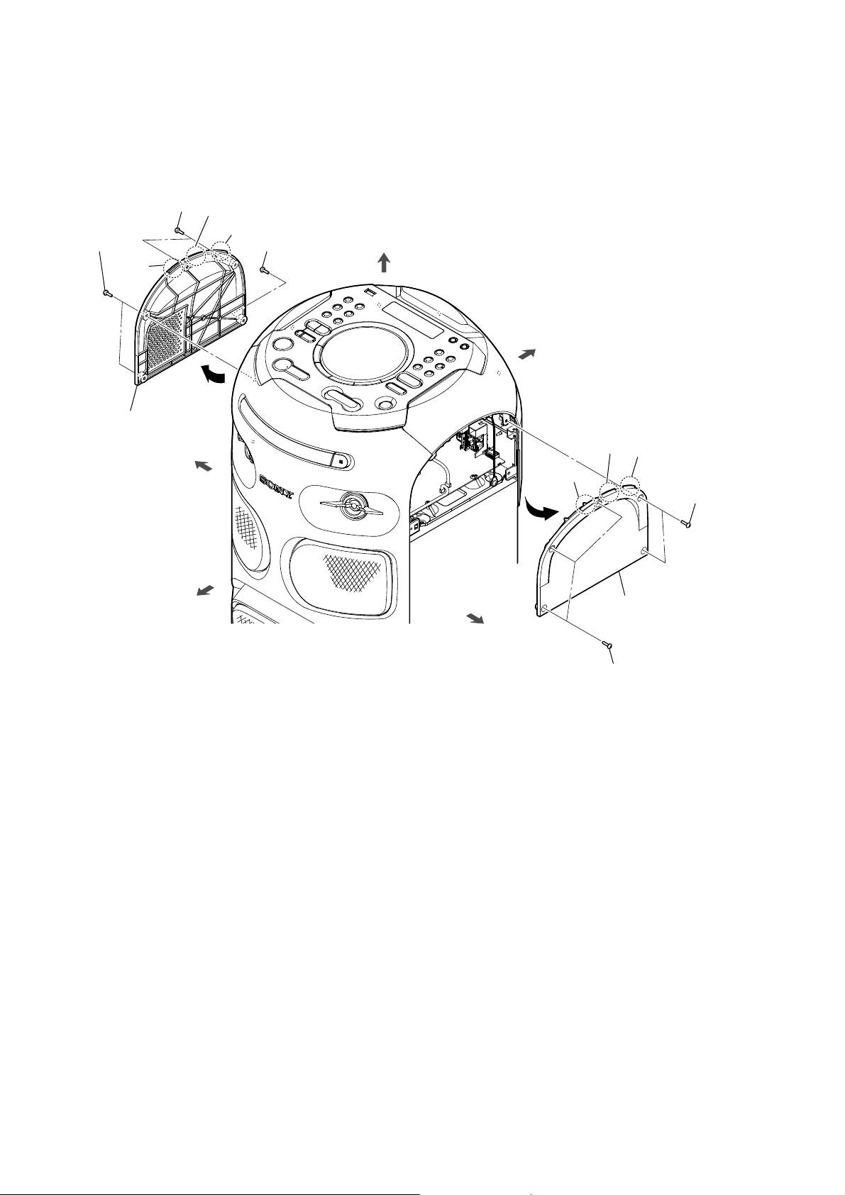
COMPONENTS IDENTIFIED BY MARK 0OR DOTTED LINE
WITH MARK 0ON THE SCHEMATIC DIAGRAMS AND IN
THE PARTS LIST ARE CRITICAL TO SAFE OPERATION.
REPLACE THESE COMPONENTS WITH SONY PARTS
WHOSE PART NUMBERS APPEAR AS SHOWN IN THIS
MANUAL OR IN SUPPLEMENTS PUBLISHED BY SONY.
License and Trademark Notice
tis a trademark of DVD Format/
Logo Licensing Corporation.
t“DVD+RW,” “DVD-RW,” “DVD+R,”
“DVD-R,” “DVD VIDEO,” and the “CD”
logos are trademarks.
tWALKMAN® and WALKMAN® logo
are registered trademarks of Sony
Corporation.
tMPEG Layer-3 audio coding
technology and patents licensed
from Fraunhofer IIS and Thomson.
tWindows Media is either a
registered trademark or trademark
of Microsoft Corporation in
the United States and/or other
countries.
tThis product is protected by
certain intellectual property rights
of Microsoft Corporation. Use or
distribution of such technology
outside of this product is prohibited
without a license from Microsoft or
an authorized Microsoft subsidiary.
tThis system incorporates Dolby*
Digital.
* Manufactured under license from
Dolby Laboratories.Dolby, Dolby
Audio,and the double-D symbol are
trademarks of Dolby Laboratories.
tThis system incorporates High-
Denition Multimedia Interface
(HDMI™) technology. The terms
HDMI and HDMI High-Denition
Multimedia Interface, and the HDMI
Logo are trademarks or registered
trademarks of HDMI Administrator,
Inc. in the United States and other
countries.
t“BRAVIA” is a trademark of Sony
Corporation.
tLDAC™ and LDAC logo are
trademarks of Sony Corporation.
tThe BLUETOOTH® word mark and
logos are registered trademarks
owned by Bluetooth SIG, Inc. and
any use of such marks by Sony
Corporation is under license. Other
trademarks and trade names are
those of their respective owners.
tThe N-Mark is a trademark or
registered trademark of NFC Forum,
Inc. in the United States and in other
countries.
tAndroid and Google Play are
trademarks of Google LLC.
tApple, the Apple logo, iPhone, and
iPod touch are trademarks of Apple
Inc., registered in the U.S. and other
countries. App Store is a service
mark of Apple Inc.
tSiri is a trademark of Apple Inc.
t“Made for iPod,” and “Made for
iPhone” mean that an electronic
accessory has been designed
to connect specically to iPod
or iPhone, respectively, and has
been certied by the developer
to meet Apple performance
standards. Apple is not responsible
for the operation of this device
or its compliance with safety and
regulatory standards. Please note
that the use of this accessory with
iPod or iPhone may aect wireless
performance.
tTHIS PRODUCT IS LICENSED UNDER
THE MPEG-4 VISUAL PATENT
PORTFOLIO LICENSE FOR THE
PERSONAL AND NON-COMMERCIAL
USE OF A CONSUMER FOR
(i) ENCODING VIDEO IN
COMPLIANCE WITH THE MPEG-4
VISUAL STANDARD (“MPEG-4
VIDEO”)
AND/OR
(ii) DECODING MPEG-4 VIDEO THAT
WAS ENCODED BY A CONSUMER
ENGAGED IN A PERSONAL AND
NON-COMMERCIAL ACTIVITY
AND/OR WAS OBTAINED FROM
A VIDEO PROVIDER LICENSED TO
PROVIDE MPEG-4 VIDEO.
NO LICENSE IS GRANTED OR SHALL
BE IMPLIED FOR ANY OTHER
USE.ADDITIONAL INFORMATION
INCLUDING THAT RELATING TO
PROMOTIONAL, INTERNAL AND
COMMERCIAL USES AND LICENSING
MAY BE OBTAINED FROM MPEG LA,
L.L.C.
HTTP://WWW.MPEGLA.COM
tAll other trademarks are trademarks
of their respective owners.
tIn this manual, ™ and ® marks are
not specied.
NOTES ON CHIP COMPONENT REPLACEMENT
• Never reuse a disconnected chip component.
• Notice that the minus side of a tantalum capacitor may be dam-
aged by heat.
CAUTION
T
he use of optical instruments with
this product will increase eye hazard.
For customers in Europe
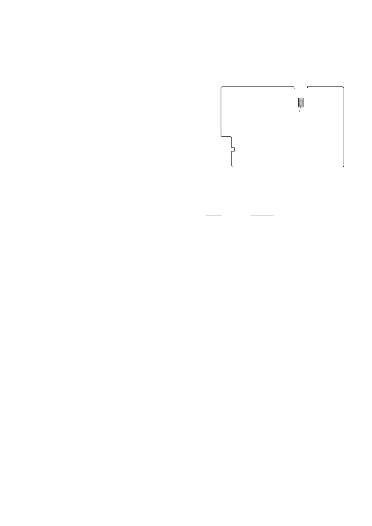
Self-diagnosis function
When letters/numbers appear
on the TV screen or the display
When the self-diagnosis function
is activated to prevent the system
from malfunctioning,a service
number appears.The service
number consists of an alphabet
and numerals (e.g. C 13 50).See the
following table for the cause and
corrective action.
First 3
characters of
the service
number
Cause and corrective
action
C 13 This disc is dirty.
tClean the disc with a
soft cloth.
C 31 The disc is not inserted
correctly.
tTurn o the system,
then turn it back on
again.Then re-insert the
disc correctly.
E XX
(XX is a
number)
To prevent a
malfunction,the system
has performed the
self-diagnosis function.
tContact your nearest
Sony dealer or local
authorized Sony service
facility and give the
5-character service
number.
Example:E 61 10

MHC-V41D
3
1. SERVICING NOTES ............................................. 4
2. DISASSEMBLY
2-1. Disassembly Flow........................................................... 9
2-2. Side Panel ....................................................................... 10
2-3. Top Panel Block-1........................................................... 11
2-4. Top Panel Block-2........................................................... 12
2-5. Loading Panel Block....................................................... 13
2-6. Loading Panel ................................................................. 14
2-7. CDM Block..................................................................... 15
2-8. FFC Holder ..................................................................... 16
2-9. Optical Pick-up Block (CMS-S76RFS7G) ..................... 17
2-10. Rear Panel Block ............................................................ 18
2-11. PARTY LED Board......................................................... 18
2-12. DC Fan, Rear Panel ........................................................ 19
2-13. Chassis Block.................................................................. 20
2-14. SMPS Board ................................................................... 21
2-15. MOTHER Board............................................................. 22
2-16. MIC Board ...................................................................... 23
2-17. PANEL Board ................................................................. 24
2-18. Electret Cap Microphone ................................................ 25
2-19. NFC Board...................................................................... 25
2-20. GESTURE Board............................................................ 26
2-21. Front Panel Block-1 ........................................................ 27
2-22. Front Panel Block-2 ........................................................ 28
2-23. SW LED Board, IR Board .............................................. 29
2-24. Loudspeaker (Tweeter) ................................................... 30
2-25. Loudspeaker (Midrange)................................................. 31
2-26. Loudspeaker (Subwoofer)............................................... 32
2-27. Chassis Block Service Position....................................... 33
2-28. Top Panel Block Service Position................................... 33
3. TEST MODE ............................................................ 34
4. ELECTRICAL CHECKS ...................................... 37
5. TROUBLESHOOTING .......................................... 38
TABLE OF CONTENTS
6. DIAGRAMS
6-1. Block Diagram - SERVO/USB/VIDEO Section - .......... 43
6-2. Block Diagram - AUDIO Section -................................. 44
6-3. Block Diagram - AMP/PANEL Section - ....................... 45
6-4. Block Diagram - POWER SUPPLY Section - ................ 46
6-5. Printed Wiring Board - MOTHER Board (Side A) - ...... 48
6-6. Printed Wiring Board - MOTHER Board (Side B) - ...... 49
6-7. Schematic Diagram - MIC Board -................................. 50
6-8. Printed Wiring Board - MIC Board - .............................. 51
6-9. Printed Wiring Board - IR Board -.................................. 51
6-10. Schematic Diagram - IR Board - .................................... 51
6-11. Printed Wiring Board - GESTURE Board -.................... 52
6-12. Schematic Diagram - GESTURE Board - ...................... 53
6-13. Printed Wiring Board - PANEL Board - ......................... 54
6-14. Schematic Diagram - PANEL Board -............................ 55
6-15. Printed Wiring Board - SMPS Board - ........................... 56
6-16. Schematic Diagram - SMPS Board - .............................. 57
7. EXPLODED VIEWS
7-1. Side Panel Section .......................................................... 59
7-2. Top Panel Section ........................................................... 60
7-3. Loading Panel Section .................................................... 61
7-4. Rear Panel Section .......................................................... 62
7-5. Chassis Section ............................................................... 63
7-6. Front Panel Section......................................................... 64
7-7. Speaker Cabinet Section ................................................. 65
7-8. CDM Block Section........................................................ 66
7-9. DVD Mechanism Deck Section
(CDM90-DVBU204) ...................................................... 67
8. ELECTRICAL PARTS LIST .............................. 68
Accessories are given in the last of the electrical parts list.

MHC-V41D
4
SECTION 1
SERVICING NOTES
The SERVICING NOTES contains important information for servicing. Be sure to read this section before repairing the unit.
NOTES ON HANDLING THE OPTICAL PICK-UP
BLOCK OR BASE UNIT
The laser diode in the optical pick-up block may suffer electro-
static break-down because of the potential difference generated by
the charged electrostatic load, etc. on clothing and the human body.
During repair, pay attention to electrostatic break-down and also
use the procedure in the printed matter which is included in the
repair parts.
The flexible board is easily damaged and should be handled with
care.
NOTES ON LASER DIODE EMISSION CHECK
The laser beam on this model is concentrated so as to be focused
on the disc reflective surface by the objective lens in the optical
pickup block. Therefore, when checking the laser diode emission,
observe from more than 30 cm away from the objective lens.
UNLEADED SOLDER
Boards requiring use of unleaded solder are printed with the lead-
free mark (LF) indicating the solder contains no lead.
(Caution: Some printed circuit boards may not come printed with
the lead free mark due to their particular size)
: LEAD FREE MARK
Unleaded solder has the following characteristics.
• Unleaded solder melts at a temperature about 40 °C higher
than ordinary solder.
Ordinary soldering irons can be used but the iron tip has to be
applied to the solder joint for a slightly longer time.
Soldering irons using a temperature regulator should be set to
about 350 °C.
Caution: The printed pattern (copper foil) may peel away if
the heated tip is applied for too long, so be careful!
• Strong viscosity
Unleaded solder is more viscous (sticky, less prone to flow)
than ordinary solder so use caution not to let solder bridges
occur such as on IC pins, etc.
• Usable with ordinary solder
It is best to use only unleaded solder but unleaded solder may
also be added to ordinary solder.
IMPORTANT NOTE OF PERFORMING THE OPERA-
TION CHECK
When performing the operation check of this unit, be sure to per-
form the operation check after checking that it is in the following
state.
• Heat sink is installed to MOTHER board
• Fan motor is connected to MOTHER board
Note: If turn the power on in the state that heat sink is not installed, there is
a possibility of damage.
Also, be sure to perform the operation check in the connect the fan
motor to the MOTHER board, and the fan motor is rotating state.
If it is necessary to perform the operation check with the heat sink
removed or the fan motor removed, set the volume to 10 or less and
perform the operation check within 1 minute.
MOTHER board
heat sink
fan motor
If “PROTECTX” (X is a number) APPEARS ON THE
DISPLAY, THEN “CHECK MANUAL” FLASHES ON
THE DISPLAY.
Immediately unplug the AC
power cord (mains lead), and
check if anything is blocking the
ventilation openings of the unit.
After you have checked and
found no problems,reconnect
the AC power cord (mains lead),
and turn on the system.
Protect Type Description:
Protect
No. Contents
1
There is possibility of over current happen at speak-
er output.
or
Unusual heat up of AMP IC by improper assembly of
heat sink.
2Defect of thermistor IC or charging circuit used by
SPM (Sound Pressure Management) system.
3 Power supply over current.
4 DC appears in SP terminal by defect of AMP IC.
6 Defect of DC FAN and DC FAN driver circuit.

MHC-V41D
5
CAPACITOR ELECTRICAL DISCHARGE PROCESSING
When removing the MOTHER board and SMPS board after check-
ing the operation of this unit, be sure to perform the discharge pro-
cessing of C2076 on the MOTHER board and C6302 on the SMPS
board before removing the boards.
When it is removed the boards without performing the discharge
processing and it is shorted the both end of C2076 on the MOTH-
ER board, it might be damaged the DAMP IC.
Perform the discharge processing with referring the figure below.
Note: Be sure to discharge using a resistor of 800 or higher.
800 :/2 W
Perform the discharge
processing with
connecting the resistor
to the hole of C6301
that is not mounted
the part.
800 :/2 W
Perform the discharge processing
with connecting the resistor between
PVDD (any one 6 to 9 pin) and PGND
(any one 1 to 5 pin) of CN2007.
– Top view –
MOTHER board SMPS board
C2076 C6302
MODEL IDENTIFICATION
Distinguish by destination code on the rear side of the main unit.
– Rear view –
AEP, UK
AUS, LA
Destination code
Serial label
Destination code
Serial label
Destination code Destination
AU1 AUS model
CEK UK model
CEL AEP model
LA9 LA model
Note: For detail about the destination, refer to “DESTINATION ABBRE-
VIATIONS” below.
DESTINATION ABBREVIATIONS
The following abbreviations for model destinations are used in this
service manual.
• Abbreviations
AEP : European area (Except for Ireland, UK), East European
area, CIS area (Moldova) and Middle East area (Jordan)
models
AUS : Australian and New Zealand models
LA : Latin American area (Except for Argentina, Brazil) model
UK : UK and Ireland models

MHC-V41D
6
IMPORTANT
DESTINATION SETTING METHOD
The destination information isn’t written in the MOTHER board for
the service.
Therefore, when the MOTHER board is replaced, be sure to per-
form the destination setting (Important work).
Note 1: The initial setting destination of the MOTHER board for the
service is “LA”. The message “D LATIN” is displayed on the
vacuum fluorescent display.
Note 2: When distinguishing the destination of the product, refer to the
“MODEL IDENTIFICATION” on page 5.
Note 3: If destination setting isn’t performed, it is possibility to occur the
defect to each operation of this unit.
Procedure:
1. Press two buttons of the [SOUND FIELD] and [TUNING +
>] simultaneously for 3 seconds during the demonstration
mode.
2. It enters the destination setting mode, the message “D LATIN”
is displayed on the vacuum fluorescent display.
Note 4: If the message “DEST LOCK” is displayed on the vacuum
fluorescent display, press the [ ] button on the remote com-
mander to release from this mode. Because the destination is
locked, and it cannot change the destination.
Initial screen display
3. Press the [ +]/[– ] buttons, destination is displayed on the
vacuum fluorescent display in following order.
[ +] [– ]
[ +] [– ]
[ +] [– ]
[ +] [– ]
[ +] [– ]
[ +] [– ]
[ +] [– ]
[ +] [– ]
[ +] [– ]
[ +] [– ]
Screen display
Setting destination by display:
Screen
display
Destination
code Model area
D ASIA ──
D INDIA ──
D ME AFC ──
D OCEANI AU1 Australia, New Zealand
D JAPAN Not used ─
D BRAZIL Not used ─
D N AME Not used ─
D LATIN LA9 Latin America (Except for Argen-
tina, Brazil)
D RUSSIA ──
D EUROPE CEL, CEK Europe (Including Ireland, UK),
East Europe, Moldova, Jordan
– Continued to the upper right –
4. Press the [ +]/[– ] buttons to select target destination, and
press the [ ] button on the remote commander.
5. The message “RESET” is displayed on the vacuum fluorescent
display, then start the initialization (power off (demonstration
mode) →power on →power off (demonstration mode)) auto-
matically.
Note 5: Don’t disconnect the power supply cord during the initializa-
tion.
Screen display
6. When the initialization is completed, the destination change is
completed.
7. When checking the setting destination, refer to the “PANEL TEST
MODE” on page 35.
NFC OPERATION CHECKING METHOD
When the MOTHER board is replaced, it is necessary to check that
pairing is normally performed.
Perform the operation check according to the following procedure.
Note: Be sure to delete paring information after checking the pairing.
1. Necessary Equipment
• NFC-compatible smartphone
Note 1: Smartphones with a built-in NFC function (OS: Android
2.3.3 or later, excluding Android 3.x).
Note 2: If the NFC-compatible smartphone has an OS version that
is older than Android 4.1.x, download and install the “NFC
Easy Connect” application.
2. Connection Method
Procedure:
1. Turn on the NFC function of the smartphone.
If the NFC-compatible smartphone has an OS version that is
older than Android 4.1.x, start the “NFC Easy Connect” ap-
plication.
2. Press the [1] button to turn the power on.
3. Touch the smartphone to the N-Mark on this unit.
4. When the NFC connection is completed, connected smart-
phone name is displayed on the vacuum fluorescent display.
5. Start the playback of an audio source on the smartphone.
Note 3: For details, refer to the operating instructions of smartphone.
3. Connection Releasing Method
Touch the smartphone to the N-Mark on this unit again.
4. Deletion of Pairing Information
Perform the “COLD RESET” on page 34.

MHC-V41D
7
CHECKING THE OPERATION AFTER REPAIR
After repair completion, connect the “iPhone/iPod”, “Walkman”,
“smartphone” etc. corresponding to this unit, and check the opera-
tion of playback, recording, charge, etc.
NOTE OF REPLACING THE ELECTRICAL PARTS ON
EACH BOARD FOR REPAIRING
Among mounted electrical parts on each board, only parts that are
described in the electrical parts list can be replaced for repairing.
The parts that are not described in the electrical parts list cannot be
replaced with single for repairing.
NOTE OF REPLACING THE MOTHER BOARD FOR
REPAIRING
Among mounted parts on the MOTHER board, only parts that are
described in the electrical parts list can be replaced for repairing.
When the parts that are not described in the electrical parts list are
defective, replace the complete mounted board.
In this service manual, the block diagram and printed wiring board
of the MOTHER board are described for reference.
Also, when the MOTHER board is replaced, be sure to refer to
“DESTINATION SETTING METHOD” and “NFC OPERATION
CHECKING METHOD” on page 6.
NOTE OF REPLACING THE PARTY LED, SW LED
NFC AND MS-476 BOARDS FOR REPAIRING
When the PARTY LED, SW LED, NFC and MS-476 boards are
defective, replace the complete mounted board or the whole parts
including the applicable board.
The mounted parts cannot be replaced with single for repairing.
In this service manual, the schematic diagram and printed wiring
board of the PARTY LED, SW LED, NFC and MS-476 boards are
not described.
Also, when the NFC board is replaced, be sure to refer to “NFC
OPERATION CHECKING METHOD” on page 6.
NOTE OF REPLACING THE SMPS BOARD FOR RE-
PAIRING
When the SMPS board is defective, replace the complete mounted
board.
The mounted parts cannot be replaced with single for repairing.
However, in this service manual, the block diagram, schematic dia-
gram and printed wiring board of the SMPS board are described
for reference.
SPREADING OF COMPOUND
When the IC2002 on the MOTHER board is replaced, spread the
compound to the touching portion between the IC2002 and the
heat sink.
– MOTHER Board (Side A) –
IC2002
compound
TEST DISCS
Use following TEST DISC when this unit confirms the operation
and checks it.
• For CD
Part No. Description
3-702-101-01 DISC (YEDS-18), TEST
4-225-203-01 DISC (PATD-012), TEST
J-2501-307-A DISC (HLX-A1), TEST
• For DVD SL (Single Layer)
Part No. Description
J-6090-069-A DISC (HLX-503), TEST (NTSC)
J-6090-088-A DISC (HLX-504), TEST (NTSC)
J-2501-305-A DISC (HLX-513), TEST (NTSC)
J-6090-077-A DISC (HLX-506), TEST (PAL)
• For DVD DL (Double Layer)
Part No. Description
J-6090-071-A DISC (HLX-501), TEST (NTSC)
J-6090-089-A DISC (HLX-505), TEST (NTSC)
J-2501-306-A DISC (HLX-514), TEST (NTSC)
J-6090-078-A DISC (HLX-507), TEST (PAL)
RELEASING THE DISC TRAY LOCK
The disc tray lock function for the antitheft of sample disc in the
shop is equipped.
It can release the lock function in the following procedure.
Releasing Procedure:
1. Press the [1] button to turn the power on.
2. Press the [FUNCTION] button to select the “DVD/CD” func-
tion.
3. Press two buttons of the [MEGA BASS] and [VOCAL FAD-
ER] simultaneously for 3 seconds.
4. The message “UNLOCKED” is displayed on the vacuum fluo-
rescent display and the disc tray is unlocked.
Note: When “LOCKED” is displayed on the vacuum fluorescent display,
the disc tray lock is not released by turning the power on/off with
the [1] button.

MHC-V41D
8
HOW TO OPEN THE TRAY WHEN POWER SWITCH TURN OFF
Note 1: Refer to “2. DISASSEMBLY” on page 9 or later, after the top panel block is removed, do this work.
Note 2: Please prepare the thin wire (clip etc. processed to the length of 8 cm or more).
2Pull out the tray in the
direction of the arrow.
1Insert the clip etc. in the hole,
and push the lever in the direction
of the arrow.
tray
–Top view –
–Left view –
DVD mechanism deck
hole
thin wire (clip etc. )
8 cm or more
front side
hole
front side

MHC-V41D
9
SECTION 2
DISASSEMBLY
• This set can be disassembled in the order shown below.
2-1. DISASSEMBLY FLOW
SET
2-2. SIDE PANEL
(Page 10)
2-3. TOP PANEL BLOCK-1
(Page 11)
2-27. CHASSIS BLOCK SERVICE POSITION
(Page 33)
2-28. TOP PANEL BLOCK SERVICE POSITION
(Page 33)
2-4. TOP PANEL BLOCK-2
(Page 12)
2-5. LOADING PANEL BLOCK
(Page 13)
2-6. LOADING PANEL
(Page 14)
2-11. PARTY LED BOARD
(Page 18)
2-12. DC FAN,
REAR PANEL
(Page 19)
2-22. FRONT PANEL BLOCK-2
(Page 28)
2-23. SW LED BOARD,
IR BOARD
(Page 29)
2-14. SMPS BOARD
(Page 21)
2-10. REAR PANEL BLOCK
(Page 18)
2-13. CHASSIS BLOCK
(Page 20)
2-15. MOTHER BOARD
(Page 22)
2-24. LOUDSPEAKER (TWEETER)
(Page 30)
2-26. LOUDSPEAKER
(SUBWOOFER)
(Page 32)
2-25. LOUDSPEAKER (MIDRANGE)
(Page 31)
2-7. CDM BLOCK
(Page 15)
2-9. OPTICAL PICK-UP BLOCK
(CMS-S76RFS7G)
(Page 17)
2-8. FFC HOLDER
(Page 16)
2-21. FRONT PANEL BLOCK-1
(Page 27)
2-16. MIC BOARD
(Page 23)
2-18. ELECTRET CAP MICROPHONE
(Page 25)
2-17. PANEL BOARD
(Page 24)
2-19. NFC BOARD
(Page 25)
2-20. GESTURE BOARD
(Page 26)
JIG
When disassembling the unit, use the following
jig for speaker removal.
Part No. Description
J-2501-238-A JIG FOR SPEAKER REMOVAL

MHC-V41D
10
Note: Follow the disassembly procedure in the numerical order given.
2-2. SIDE PANEL
4side panel (R)
1three screws
(BVTP3 u8)
2
4side panel (L)
1two screws
(BVTP3 u8)
1two screws
(BVTP3 u8)
1two screws
(BVTP3 u8)
1screw
(BVTP3 u8)
3claw
3claw
3claw
front side
top side
rear side
left side
right side
2
3claw
3claw
3claw

MHC-V41D
11
2-3. TOP PANEL BLOCK-1
• Continued on 2-4 (page 12).
WireVHWWLQJ
5microphone wire connector
(CN3001)
9flexible flat cable (7P) (CN601)
(from MIC board)
8PANEL board cable
connector (CN451)
7flexible flat cable (19P) (CN103)
(from PANEL board)
6flexible flat cable (6P) (CN105)
(from NFC board)
0flexible flat cable (7P) (CN120)
(from GESTURE board)
terminal side
CN103
The opposite side
is terminal side.
The opposite side
is terminal side.
CN105CN3001
MOTHER
board
CN451
CN120
CN601
–5LJKWYLHZ–
–5LJKWYLHZ–
front side rear side
right side
front side
rear side
The opposite side
is terminal side.
$(38.$86
2. NG
front side
rear side
top side
2screw
(BVTP3 u8)
4MIC board wire
3PANEL board wire
$(38.$86
$(38.$86
Note: During reassembly, use new insulock ties
to fasten the wires back in place as they
were before disassembly.
1Cut the insulock tie.
:LUHVHWWLQJ
microphone
wire
microphone
wire $(38.$86
insulock tie
PANEL board
cable
MIC board wire
PANEL board wire

MHC-V41D
12
2-4. TOP PANEL BLOCK-2
4two claws
3Lift up rear side of the top
panel block in the direction
of the arrow.
7top panel block
5Remove the top panel block
in the direction of the arrow.
2three screws
(BVTP3 u8)
1screw
(BVTP3 u8)
1screw
(BVTP3 u8)
front side
rear side
top side
top panel block
6PANEL board cable
connector (CN7600)
(AEP, UK, AUS)
(AEP, UK, AUS)
(AEP, UK,
AUS)

MHC-V41D
13
2-5. LOADING PANEL BLOCK
2Pull out the tray in the
direction of the arrow.
1Insert the clip etc. in the hole, and
push the lever in the direction of
the arrow.
rear side
top side
OK NG
5loading panel block
(See Fig. A)
DVD mechanism deck
clip etc.
(8 cm or more)
tray
–Left view –
hole
front side
lever
hole
4Remove the loading
panel block in the
direction of the arrow.
left side
< Fig. A >
– Top view – – Top view – wide
narrow
The gaps at both ends are equal.
(installed horizontally)
The gaps at both ends are not equal.
(installed at an angle)
3claw
3claw
tray
loading panel block
tray
loading panel block
front side
DVD mechanism deck top side
Note about installing the loading panel block

MHC-V41D
14
2-6. LOADING PANEL
4spring (LP)
8base loading
0loading panel
7loading cushion
(See Fig. D)
2hemilon cushion
(See Fig. B)
hemilon cushion
hemilon cushion
hemilon
cushion
3DVWLQJSRVLWLRQRIWKHORDGLQJFXVKLRQ
front side
front side
rear side
rear side
bottom side
front side
top side
front side
rear side
loading cushion
guide line
guide line
guide line
guide line
)LJ'!
3DVWLQJSRVLWLRQRIWKHKHPLORQFXVKLRQ
)LJ%!
)LJ&!
OK NG
5claw
5claw
9hemilon cushion
(See Fig. C)
9hemilon cushion
(See Fig. C)
6Remove the base loading
block in the direction of
the arrow.
3Draw the spring (LP)
out of the two holes.
1RWHDERXWLQVWDOOLQJWKHVSULQJ/3
–%RWWRPYLHZ–
–%RWWRPYLHZ––%RWWRPYLHZ–
–,QQHUYLHZ–
–)URQWYLHZ–
base loading
loading panel block
loading panel
The spring loading has good balance.
(the center of the spring is centered)
spring (LP)
The spring loading has poor balance.
(the center of the spring is shifted to
the left or right)
1hemilon
(See Fig. E)
1hemilon
(See Fig. E)
)LJ(!
3DVWLQJSRVLWLRQRIWKHKHPLORQ
hemilon hemilon
spring (LP)
front side
rear side
front side
rear side
–%RWWRPYLHZ–guide line
Bend. Bend.
loading panel block

MHC-V41D
15
2-7. CDM BLOCK
8Remove the CDM block
in the direction of the arrow.
3flexible flat cable (24P) (CN302)
(from optical pick-up block)
(See Fig. F)
6two screws
(BVTP3 u8)
front side
DC fan cable
rear side
2flexible flat cable (5P)
(CN303) (from MS-476 board)
(See Fig. F)
1OP cable
connector
(CN402)
(See Fig. F)
'&IDQFDEOHVHWWLQJ
:LUHVHWWLQJ
MOTHER board
right side
coating clip
7two screws
(BVTP3 u8)
groove
Note 2: The DC fan cable must not touch
the heat sink.
heat sink
hole
boss
boss
hole
9CDM block
Note 1: When installing the CDM block,
align the two bosses and two holes.
–5LJKWYLHZ–
front side rear side
flexible flat cable (5P)
(from MS-476 board)
CN303
MOTHER board
)LJ)!
terminal side
CN302
CN402 terminal side
flexible flat cable (24P)
(from optical pick-up block)
OP cable
heat sink
top side
4Remove the DC fan cable
from the coating clip.
5Remove the DC fan cable
from the groove.
–&'0EORFNERWWRPYLHZ–

MHC-V41D
16
2-8. FFC HOLDER
1two screws
(BVTP3 u8)
4DVD mechanism deck block
1two screws
(BVTP3 u8)
2
3CDM bracket block
boss
boss
claw
6Remove the FFC holder
in the direction of the arrow.
8FFC holder (See Fig. H)
Note: When installing the FFC holder,
check that installed firmly
two bosses and claw.
hole
3DVWLQJSRVLWLRQRIILODPHQWWDSHVXEPDWHULDO
There is a gap.
There is no gap.
OK NG
–BRWWRPYLHZ–
5filament tape
(sub material)
(See Fig.G)
filament tape
(sub material)
filament tape
(sub material)
DVD mechanism deck block
7Draw the flexible flat cable
out of the hole.
5filament tape
(sub material)
(See Fig.G)
front side
rear side
top side
front side
rear side
top side
Turn over.
1RWHDERXWLQVWDOOLQJWKH))&KROGHU
)LJ*!
DVD mechanism
deck block
flexible flat cable
(24P)
flexible flat cable
(5P)
)LJ+!

MHC-V41D
17
2-9. OPTICAL PICK-UP BLOCK (CMS-S76RFS7G)
5insulator screw
8flexible flat cable
(24P)
9MOTHER board connection
cable connector
7connector
0insulator
0insulator
0insulator
0insulator
qa optical pick-up block
(CMS-S76RFS7G)
6Remove the optical pick-up block
in the direction of the arrow.
4three claws
(See Fig. J)
1claw
1claw
1claw
1claw
1claw
2chuck holder block
– Bottom view –
– Top view –
3Draw out the tray.
Note: When you can not draw out the tray,
please refer to “HOW TO OPEN THE
TRAY WHEN POWER SWITCH
TURN OFF” on page 8.
5insulator screw
5insulator screw
5insulator screw
The opposite side
is terminal side.
front side
rear side
Wire setting
< Fig. J >
1claw
front side
rear side
MOTHER board
connection cable
< Fig. K >
front side
rear side
top side

MHC-V41D
18
2-10. REAR PANEL BLOCK
5three screws
(BVTP3 u8)
5four screws
(BVTP3 u8)
5screw
(BVTP3 u8)
1screw
(BVTP3 u8)
4tapping screw
(3.5 u14)
front side
rear side
3DC fan cable connector
(CN2001)
4tapping screw
(3.5 u14)
4tapping screw
(3.5 u14)
6
7rear panel block
Note: When installing the rear panel block,
be careful not to pinch the DC fan cable.
right side
2service connector cap
2-11. PARTY LED BOARD
top side
3two screws
(BVTP2.6 u8)
2party lens block
1claw
1claw
hole
boss
boss
hole
hole
4PARTY LED board block
Note 1: When installing the
PARTY LED board
block, align the two
bosses and two holes.
hole
boss
Turn over. 6party LED bracket
5screw
(BVTP2.6 u8)
5screw
(BVTP2.6 u8)
7party light cushion
8PARTY LED board
Note 2: When installing the
PARTY LED board,
align the three bosses
and three holes.
boss boss
hole
,QVWDOODWLRQSRVLWLRQRIWKHSDUW\OLJKWFXVKLRQ
front side
rear side
party light cushion
PARTY LED board
rear panel block
LED

MHC-V41D
19
2-12. DC FAN, REAR PANEL
guide line fan cushion
1screw
(BVTP3 u8)
1screw
(BVTP3 u8)
1two screws
(BVTP3 u8)
3fan cushion
,QVWDOODWLRQSRVLWLRQRIWKHIDQFXVKLRQ
4hemilon 4hemilon
5rear panel
–,QQHUYLHZ–
hemilon
guide line –2XWHUYLHZ–
–2XWHUYLHZ–
top side
rear panel
2DC fan
Note: When installing the DC fan,
be careful not to pinch the
DC fan cable.
3two fan
cushions
3fan cushion
3DVWLQJSRVLWLRQRIWKHKHPLORQ
hemilon
rear panel
hemilon
Fold.
hemilon
guide line
Fold.
top side
rear panel
top side

MHC-V41D
20
2-13. CHASSIS BLOCK
front side
– Left view –– Right view –
2SW LED board cable connector
(CN104)
1IR board cable connector
(CN127)
rear side
left side
3speaker cable connector
(CN2021)
4tapping screw
(3.5 u14)
4tapping screw
(3.5 u14)
4three tapping screws
(3.5 u14)
5claw
5claw
7chassis block
6
Other manuals for MHC-V41D
1
Table of contents
Other Sony Stereo System manuals

Sony
Sony SRS-BTX300 User guide

Sony
Sony HCD-EC55 - Receiver System User manual

Sony
Sony XO-D301 User manual

Sony
Sony HCD-VX777 User manual

Sony
Sony HCD-GTX88 User manual

Sony
Sony ZS-SAT1 User manual

Sony
Sony SA-V90DW Reference guide

Sony
Sony HCD-GX30 User manual

Sony
Sony XES-Z50 User manual

Sony
Sony ZS-X1 - Cd Boombox User manual

Sony
Sony MHC-W55 User manual

Sony
Sony SRS-ZR5 User manual

Sony
Sony LBT-V8900S User manual

Sony
Sony MHC-NX300AV User manual

Sony
Sony HCD-EC68 User manual

Sony
Sony MHC-GN700 User manual

Sony
Sony CMT-CP11 User manual

Sony
Sony CMT-X7CD User manual

Sony
Sony MHC-V71 User manual

Sony
Sony LBT-XGR600 - Compact Hi-fi Stereo System User manual