—2 —
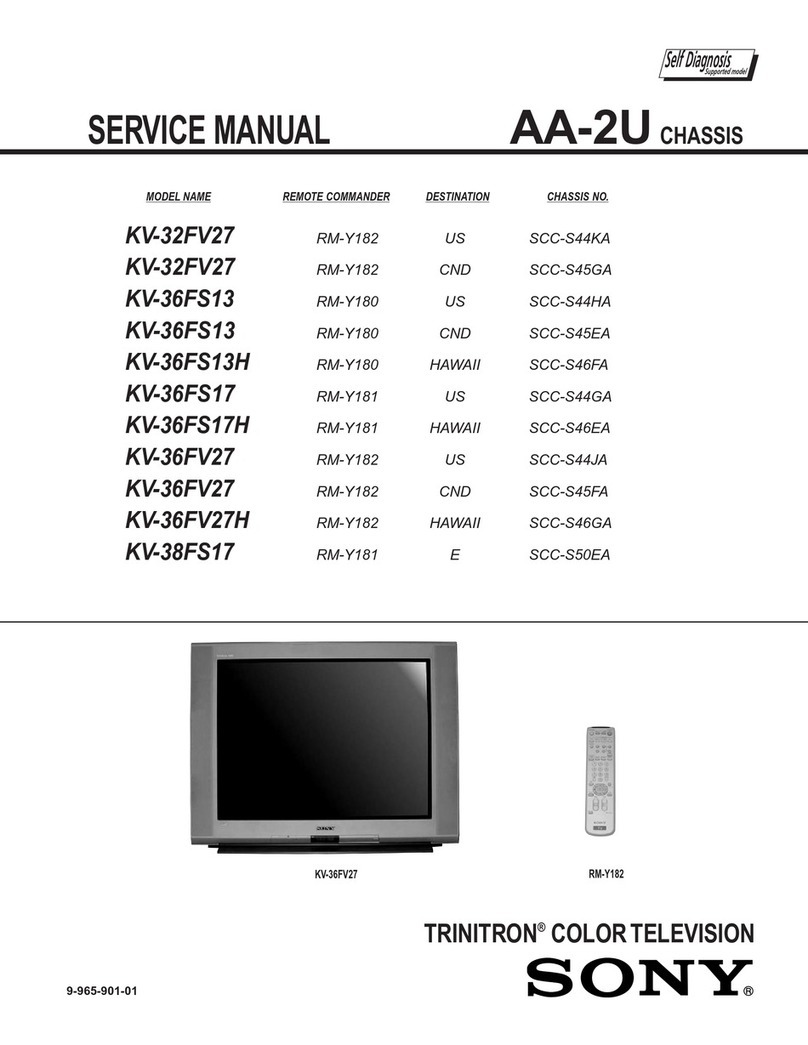
KV-32HS20/36HS20/36HS20H/32XBR450/36XBR450/36XBR450H
TABLE OF CONTENTS
Specifications ................................................................................. 3
Warnings and Cautions .................................................................. 4
Safety Check-out............................................................................ 5
Self-Diagnostic Function................................................................. 6
1. Disassembly
1-1. Rear Cover Removal.............................................................. 8
1-2. Chassis Assembly Removal................................................... 8
1-3. Service Position ..................................................................... 8
1-4. Picture Tube Removal ............................................................ 9
Anode Cap Removal Procedure..................................................... 9
2. Set-up Adjustments
2-1. Beam Landing...................................................................... 10
2-2. V-Pin and V-Cen Adjustment................................................ 11
2-3. Convergence........................................................................ 11
2-3.1. Vertical and Horizontal Static Convergence............. 11
2-3.2. Operation of BMC (Hexapole) Magnet..................... 11
2-3.3. TLH Plate Adjustment .............................................. 11
2-3.4. Screen Corner Convergence ................................... 12
2-3.5. Dynamic Convergence Adjustment.......................... 12
2-4. Focus Adjustment................................................................. 12
2-5. Screen (G2).......................................................................... 12
2-6. Picture Quality Adjustments................................................. 13
2-6.1. Video Input - Two Picture Sub Contrast
Adjustment............................................................... 13
2-6.2. Video Input - Sub Hue/Sub Color Adjustment.......... 13
2-6.3. RF Input - Two Picture Sub Contrast Adjustment..... 14
2-6.4. RF Input - Sub Hue/Sub Color Adjustment.............. 14
2-7. White Balance (CRT) and Sub Bright Adjustment ............... 15
2-8. Raster Center Adjustment.................................................... 15
2-9. Picture Distortion Adjustments............................................. 15
2-9.1. NTSC (DRC) Full Mode Adjustment ........................ 15
2-9.2. 1080i HD Mode Adjustment..................................... 16
2-9.3. Vertical Compresses Mode Check and
Confirmation............................................................. 16
SECTIONTITLE PAGE
3. Safety Related Adjustments
3-1. RV8001, 8002, 8003 Confirmation Method and
HV Service Adjustments ...................................................... 17
3-2. B+ Max Confirmation ........................................................... 17
3-3. HV Service Flowchart .......................................................... 17
4. Circuit Adjustments
4-1. Setting the Service Adjustment Mode.................................. 18
4-1.1 Resetting the Data ................................................... 18
4-2. Memory Write Confirmation Method .................................... 18
4-3. Remote Adjustment Buttons and Indicators......................... 18
5. Diagrams
5-1. Circuit Board Location.......................................................... 48
5-2. Printed Wiring Boards and Schematic Diagrams................. 48
5-3. Diagrams
Block Diagram...................................................................... 49
A Board ................................................................................ 53
B Board ................................................................................ 61
BC Board.............................................................................. 71
C Board................................................................................ 73
D Board................................................................................ 75
HA Board.............................................................................. 83
HB Board.............................................................................. 84
S Board ................................................................................ 85
U Board................................................................................ 86
W Board ............................................................................... 88
5-4. Semiconductors ................................................................... 90
6. ExplodedViews
6-1. Chassis ................................................................................. 92
6-2. Picture Tube (KV-32HS20/32XBR450 ONLY)........................ 93
6-3. Picture Tube (ALL EXCEPT KV-32HS20/32XBR450).......... 94
7. Electrical Parts List ......................................................................... 95
SECTIONTITLE PAGE
