Sopex SXF8011W User manual

INSTRUCTION MANUAL
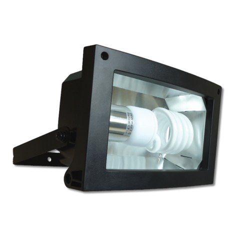
SOPEX Explosion Proof LED Floodlights
Models: SXF8011W/8011N/8012W/8012N/8013W/8013N
•Do not open the floodlight when energised
•Read the instruction manual before installation
•The floodlight must be installed and maintained by an authorised trained person
•All modifications on this floodlight are forbidden
SOPEX Innovations Pte Ltd
TECHNICAL SPECIFICATIONS
Model Power
Rating Current Lumens
Output Peak
Candlepower Beam
Angle
SXF8011W 78W 0.78A@100V / 0.34A@220V 6000 lumens 2000 cd 108°
SXF8011N 78W 0.78A@100V / 0.34A@220V 5680 lumens 7500 cd 36°
SXF8012W 156W 1.56A@100V / 0.69A@220V 12000 lumens 4000 cd 108°
SXF8012N 156W 1.56A@100V / 0.69A@220V 11800 lumens 16000 cd 36°
SXF8013W 234W 2.34A@100V / 1.03A@220V 17100 lumens 6400 cd 108°
SXF8013N 234W 2.34A@100V / 1.03A@220V 16900 lumens 22000 cd 36°
OVERALL DIMENSIONS AND WEIGHT
SXF8011W / SXF8011N
SXF8011W/8011N SXF8012W/8012N/8013W/8013N
Certification code
II 2 G D
Ex
db eb op is IIC T6/T5 Gb
Ex tb op
is IIIC T80°C / T100°C Db
II 2 G D
Ex
db eb op is IIC T6/T5/T4 Gb
Ex tb op
is IIIC T80°C / T100°C / T135°C Db
Ambient Temperature
-
40°C ≤ Ta ≤ +40°C / +50°C
-
40°C ≤ Ta ≤ +30°C / +40°C / +50°C
Hazardous Locations
Gas: Zones 1 & 2 Dust: Zones 21 & 22
Ingress Protection
IP66/67
Protection Class
Class 1
Voltage
AC 100-120V/220-240V 50/60Hz
Power Factor
0.995 at 100V, 0.996 at 220V
CCT
5000K
Service Life
100,000h at ambient temperature of 40°C
SXF8011W: 5.8 kg
SXF8011N: 6.0 kg
Weight:
Page 1 of 4

SXF8012W / SXF8012N
SXF8013W / SXF8013N
SOPEX Innovations Pte Ltd
SXF8012W: 11.5 kg
SXF8012N: 11.7 kg
SXF8013W: 17.0 kg
SXF8013N: 17.3 kg
Weight:
Weight:
Page 2 of 4

SOPEX Innovations Pte Ltd
INSTALLATION INSTRUCTIONS
•The installer and/or maintenance personnel must verify the floodlight’s certification code is
compatible with the environmental and authorised conditions of the site.
•Check the power rating label to ensure the floodlight is suitable for the electrical main supply.
•All inadequate and wrong installation or usage will render the warranty void.
•Ensure power is turned off before installation or troubleshooting. Do not open any part of the
floodlight when it is energised.
•The floodlight has one power cable entry at the junction box that is fitted with an ATEX and IECEx
approved M20 cable gland for unarmoured cable of diameter 11.0mm to 15.0mm. Second cable
gland or glands of other sizes are options sold separately.
•Open the junction box by unscrewing the 4 screws on the cover.
•Use a 3 core power cable that is compatible with the cable gland size.
•Strip the outer sheath at the connecting end of the cable to expose the 3 insulated wires.
•Insert the power cable through the gland until the outer sheath appears through the cable gland
bore inside the junction box.
•Using a torque wrench spanner, tighten the outer nut of the gland with 32.5Nm installation torque
to properly seal the cable in the gland.
•Strip the insulation at the tip of the 3 insulated wires to expose the conductors for connection.
•Connect the 3 insulated wires to the terminal block inside the junction box according to their
respective positions: Live (L - brown), Neutral (N - blue) and Protective Earth (PE - Yellow/Green).
•The terminal block is able to receive wires with cross section up to 4mm2. Ensure the bare copper of
the wires are fully inserted into the terminals and the screws are sufficiently tightened.
•Close the junction box cover and tightening the 4 screws firmly.
SPECIAL CONDITION FOR SAFE USE
When operated at ambient temperature below -20°C, the tempered glass cover of the
floodlight becomes more brittle and can only withstand impact energy of 1J. Please handle with
care in low temperature environment.
TEMPERATURE CLASSIFICATION
Ambient Temperatures
-40°C to +30°C -40°C to +40°C -40°C to +50°C
SXF8011W T6 and T80°C T5 and T100°C
SXF8011N T6 and T80°C T5 and T100°C
SXF8012W T6 and T80°C T5 and T100°C T4 and T135°C
SXF8012N T6 and T80°C T5 and T100°C T4 and T135°C
SXF8013W T6 and T80°C T5 and T100°C T4 and T135°C
SXF8013N T6 and T80°C T5 and T100°C T4 and T135°C
Insulated wire
Outer nut of
cable gland
Junction Box Outer sheath of
power cable
Page 3 of 4

SOPEX Innovations Pte Ltd
8 Penjuru Lane, Singapore 609189
DECLARATION OF CONFORMITY
We declare that the LED floodlight is designed to be used in potentially explosive atmospheres
described below:
SOPEX Explosion Proof LED Floodlight
Types: SXF8011W/8011N/8012W/8012N/8013W/8013N
Ex II 2 G Ex db eb op is IIC T6/T5/T4 Gb
Ex II 2 D Ex tb op is IIIC T80°C / T100°C / T135°C Db
satisfies: - the provisions of Directive 2014/34/EU
- standards: EN 60079-0:2012+A11:2013
EN 60079-1:2014
EN 60079-7:2015
EN 60079-28:2015
EN 60079-31:2014
- the provisions of IEC 60533 (electromagnetic compatibility)
- the type and its variants have received the EC examination certification type:
EPS 18 ATEX 1 191 X / IECEx EPS 18.0097X
Subject to use for the purpose for which it is designed and installation in accordance with standards
in force and with recommendations of the manufacturer.
The certification body is EPS - Bureau Veritas Consumer Products Services Germany GmbH.
Symptom Solution
Floodlight does not turn on •Check for proper cable termination and good connection
•Verify the power supplied has the right voltage
•If connected to external controls, ensure the control is working
properly
Floodlight is rocking •Ensure the position locking mechanism is properly secured
•Check the mounting screws are firmly tightened
TROUBLESHOOTING
•Use AISI 316 stainless steel screws to secure / mount the floodlight.
•The LED floodlight can be turned on or restarted instantly with full brightness. No warm-up time is
required.
•Other than the junction box, no other parts of the floodlight should be opened for installation,
modification or maintenance.
•To ensure the junction box is waterproof and maintain the floodlight’s warranty:
a) Check the compatibility of the cable gland size with the power cable diameter. Tightening of
the cable gland seal on the cable sheath must by steady.
b) Check the base of the cable gland is firmly screwed into the junction box and does not turn
loosely.
c) Ensure the gasket of the junction box is correctly positioned. Periodically check the gasket.
If the gasket is in poor condition, replace it immediately.
•All repair works and spare parts must be sourced from SOPEX Innovations Pte Ltd.
Page 4 of 4
This manual suits for next models
5
Table of contents

