SOR 1267AFR-1 Instruction manual

Form 1630 (09.18) ©SOR Inc.
1/8
The 1267 Air Filter Regulator is designed for air or
gas service. Maximum allowable inlet pressure is
250 psi (17 bar). Operating temperatures are 0°F
to 160°F (-18°C to 71°C). The 1267AFR has low
capacity internal relief which provides very limited
downstream overpressure protection.
1267AFR
Air Filter Regulator
General Instructions
Registered Quality System to ISO 9001
Design and
specifications are
subject to change
without notice.
For latest revision, go to
sorinc.com
NOTE: If you suspect that a product is defective, contact the factory or the SOR
®
Representative
in your area for a return material authorization number (RMA). This product should only be
installed by trained and competent personnel.
Table of Contents
Installation.......................................2
Calibration .......................................2
Maintenance.....................................3
Specications ...................................4
Materials.........................................4
Parts List .........................................5
Dimensions ................................... 6-7
The internal relief valve in the 1267AFR does
not provide full overpressure protection and
is designed for minor seat leakage only. To
avoid exceeding outlet pressure limits in
service, a pressure-relieving or pressure-
limiting device should be provided. Leakage,
equipment damage, or personal injury can
result from over-pressuring the regulator.
All SOR instructions, as well as applicable local, state, and federal codes
and regulations should be adhered to when performing installation,
operation, or maintenance of a regulator. Personal injury, equipment
damage, or leakage can occur if the regulator is over-pressured or physically
damaged. To avoid physical damage the regulator should be installed in a
safe location. The regulator shouldn’t be installed in systems that exceed
the specied pressure limit of 250 psi (17 bar). If leakage develops, then
maintenance is required. Failure to remove the regulator from service
immediately may create a hazardous situation.
Tbl fCtt
es
d
e
,

2/8
Form 1630 (09.18) ©SOR Inc.
Installation
If continuous operation is required during inspection or maintenance, a bypass
must be installed.
Inspect the regulator for any damage, foreign substances, or blockages.
Clean all pipelines to remove dirt and scale prior to installation.
Apply pipe compound to the male pipeline threads. Use caution to prevent the
sealant from getting inside the regulator.
Install the regulator as close as possible to the instrument or tool it will be
servicing and orient it such that the direction of gas flow is from the “IN” to the
“OUT” connection as marked on the body.
For best drainage, position the drain valve until it is at the lowest point on the drip
well housing. Positioning of the drain valve may be improved by rotating the drip
well with respect to the body.
The exhaust port should be kept free and unplugged. Rotating the bonnet relative
to the body may change the vent hole orientation. Exhaust may be remotely vented
by installing tubing to the ¼” NPT port (“E” Accessory – Tapped Exhaust).
The 1267AFR may vent some gas to the atmosphere. If integrated into a
hazardous system, this vented gas could accumulate and if ignited it could
cause personal injury, death, or equipment damage. For use in a hazardous
system, the regulator must be vented to a remote and safe location. The vent
line or stack opening must be protected from condensation or clogging.
Calibration
Before turning on air supply, loosen the adjusting screw by rotating it counter-
clockwise. Do this until there is no compression in the control spring.
Apply air supply, and tighten adjusting screw by rotating it clockwise. Tightening
the screw will increase the output pressure. Pressure should always be monitored
during startup to ensure that the regulator isn’t over-pressured.
Once desired pressure setting is reached, tighten the locknut to maintain the
calibration and prevent accidental adjustment.

Form 1630 (09.18) ©SOR Inc.
3/8
Maintenance
TO DRAIN CONDENSATE
Slowly open the drain valve by turning clockwise.
Bleed all accumulated liquid and then close the drain valve.
TO CLEAN THE FILTER
Shut off the supply pressure and relieve all internal pressure from the regulator.
Drain condensate from the drip well per the above procedure.
Remove the 4 corner bolts from the bottom of the unit and remove the drip well
housing.
Remove the filter-retaining screw.
Remove the filter retainer, the filter o-rings, and filter.
Clean the parts and reassemble in reverse order.
TO CLEAN THE PINTLE ASSEMBLY
Shut off the supply pressure and relieve all internal pressure from the regulator.
Drain condensate from the drip well per the above procedure.
Remove the 4 corner bolts from the bottom of the unit and remove the drip well
housing.
Remove the filter-retaining screw.
Remove the pintle spring; the pintle and pintle spring will be accessible upon
removal of the base.
Clean the parts as needed; apply a high quality lubricant to all cleaned o-rings.
Reassemble the parts in reverse order.
TO CLEAN THE DIAPHRAGM ASSEMBLY
Loosen the adjusting screw until the spring is no longer compressed.
Remove the 4 bonnet screws and separate the bonnet from the body of the
regulator. Remove the spring and spring guide.
Remove the diaphragm assembly and clean as required.
Reassemble the parts in reverse order. After placing the diaphragm assembly on
the body, push the assembly down to ensure the pintle is seated properly and
strokes smoothly.
To avoid personal injury or equipment damage resulting from sudden release
of pressure or ignition of accumulated gas, isolate the regulator from the
system and bleed all of its internal pressure before attempting maintenance
procedures.

4/8
Form 1630 (09.18) ©SOR Inc.
Specications
Port Size (Gauge
Ports 1/4” NPT) 1/4” NPT 1/2” NPT (High flow
capacity)
Cv Values 0.5 at 150 psig supply and 80
psig setpoint
2.5 at 150 psig supply and 80
psig setpoint
Effect of Supply
Pressure Varia-
tion
Less than 0.25 psig (0.017
bar) for 25 psig (1.7 bar)
change
Less than 0.5 psig (0.035 bar)
for 25 psig (1.7 bar) change
Weight 1.2 lbs (0.54 kgs) 1.71 lbs (0.78 kgs)
Output Ranges 0-30 psig (0-2 bar), 0-60 psig (0-4 bar), 0-120 psig (0-8 bar)
Maximum Supply
Pressure 250 psig (17 bar)
Mounting Pipe, Bracket or Direct (through body mounting holes)
Filter 40 micron (“F” Accessory – 5 micron)
Exhaust Capacity 0.1 scfm (3 Nl/min) with downstream pressure 5 psig (0.3 bar)
above setpoint
Sensitivity 1 in. wc
Air Consumption Less than 5 scfh (2.5 Nl/min)
Temperature
Limits 0°F to 160°F (-18°C to 71°C)
Operating Media Air, Inert Gas, and Sweet Natural Gas
Materials
Component Standard Construction NACE Construction
(“NC” Accessory)
Body Diecast Aluminum Alloy, Irridite and Baked Epoxy Finish
Filter Polyethylene
Phenolic Impregnated Cellulose
Diaphragm Nitrile Elastomer and Nylon
Fabric Viton
Valve Seat Nitrile Elastomer Viton
Other Parts Brass, Zinc, Plated Steel, and
Acetal
316SS, Aluminum, and Heat
Treated Plated Steel

Form 1630 (09.18) ©SOR Inc.
5/8
Parts List
1267AFR-1 (1/4” NPT)
1267AFR-2 (1/2” NPT)
Parts List – 1267AFR-1 (1/4” NPT)
Item Qty. Description
7 1 Body
11 1 Base Assembly
12 4 10-24 Dripwell Screw
14 1 Filter Retainer
15 1 Dripwell
16 1 Drain Valve
Parts List – 1267AFR-2 (1/2” NPT)
Item Qty. Description
7 1 Body
9 1 Valve Spring
11 1 Base Assembly
12 4 10-24 Dripwell Screw
13 1 Collar
16 1 Filter Retainer
17 1 Screw, Retainer
18 1 Dripwell
19 1 Drain Valve
1
267AR 1/2 NPT

6/8
Form 1630 (09.18) ©SOR Inc.
Dimensions
1267AFR-1 (1/4” NPT)
Port Size
(NPT)
A
in. (mm)
B
in. (mm)
C
in. (mm)
D
in. (mm)
E
in. (mm)
F
in. (mm)
G
in. (mm)
1/4” 2.66
(67.6)
1.0
(25.4)
3.42
(86.8)
7.15
(181.6)
2.25
(57.2)
3.19
(81.0)
1.22
(31.0)
Dimensions shown are for reference only. Linear = in./mm
DRAIN
VALVE
ADJUST SCREW
ASSEMBLY
BONNET
DIAPHRAGM
ASSEMBLY
FILTER
VALVE
BODY
ASSEMBLY
DRIPWELL
HOUSING
RANGE SPRING
SPRING GUIDE

Form 1630 (09.18) ©SOR Inc.
7/8
1267AFR-2 (1/2” NPT)
DRAIN
VALVE
VALVE
BODY
ASSEMBLY
DRIPWELL
HOUSING
RANGE SPRING
SPRING GUIDE
ADJUST SCREW
ASSEMBLY
BONNET
DIAPHRAGM
ASSEMBLY
FILTER
Port Size
(NPT)
A
in. (mm)
B
in. (mm)
C
in. (mm)
D
in. (mm)
E
in. (mm)
F
in. (mm)
G
in. (mm)
1/2” 2.83
(71.9)
1.17
(29.7
6.06
(153.7)
9.78
(248.4)
2.25
(57.2)
3.36
(85.3)
1.39
(35.3)

8/8
Form 1630 (09.18) ©SOR Inc.
14685 West 105th Street, Lenexa, KS 66215
913-888-2630
800-676-6794 USA
Fax 913-888-0767
Registered Quality System to ISO 9001
Printed in USA sorinc.com
This manual suits for next models
1
Table of contents
Popular Controllers manuals by other brands
Smartgen
Smartgen APC715 user manual
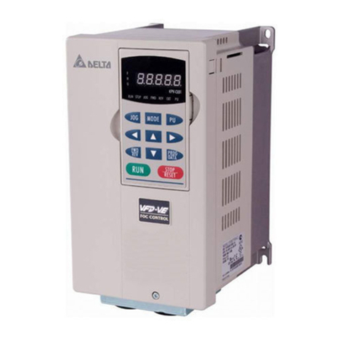
Delta Electronics
Delta Electronics AC Motor Drive VFD-VE Series user manual

Edgewater Networks
Edgewater Networks EdgeMarc 250W Hardware installation guide
Array electronic
Array electronic SH-300 user manual
Samson
Samson 3374 Mounting and operating instructions
Emotron
Emotron VS10 Instruction
