SoRoTo 40L-30 User manual
40 L
120 L
80 L
200 L
300 L
100 L
07.11.16
MANUAL
Forced Action Mixers
English

GB / 2 3 / GB
TABLE OF CONTENTS
SoRoTo 40L/80L/100L/120L .........................p. 3
Application .....................................................p. 3
Before use......................................................p. 3
Before connecting the power supply............p 3
Operating the SoRoTo forced action mixer ..p. 4
Cleaning / maintenance ...............................p. 4
Transport........................................................p. 5
Safety .............................................................p. 5
Technical data ...............................................p. 5
Contact details...............................................p. 6
Special features/spare parts .......................p. 7
Spare part list – 40 L ....................................p. 8
Spare part list – 80 L ....................................p. 10
Spare part list – 100 L..................................p. 12
Spare part list – 120 L..................................p. 14
SoRoTo 200L/300L ..........................................p. 16
Application .....................................................p. 16
Before use......................................................p. 16
Before connecting the power supply............p 16
Operating the SoRoTo forced action mixer ..p. 16
Cleaning / maintenance ...............................p. 17
Transport........................................................p. 18
Safety .............................................................p. 19
Technical data ...............................................p. 19
Contact details...............................................p. 19
Spare part list – 200 L..................................p. 20
Spare part list – 300 L..................................p. 22
EC Declaration of Conformity ...........................p. 24
MANUAL APPLIES TO
SoRoTo 40L/80L/100L/120L
APPLICATION
The SoRoTo Forced Action Mixers are ideal for mixing all kinds of ma-
terials used in the building industry, as well as for tasks where high
demands are imposed on quality of the mix.
When mixing materials containing aggregates, we recommend using
the SoRoTo Mixer arms set with rubber blades. (NOTE: The SoRoTo
Forced Action Mixer 40L/30 is not suited for mixing materials contain-
ing aggregates).
When using mixer arms equipped with steel blades to mix materials
containing aggregates, the mixer arms may work their way upwards and
eventually stop turning.
BEFORE USE
Before starting the mixer, the telescopic legs must be positioned for
the right height for draining into a bucket or wheelbarrow. The easiest
way for adjusting the legs is to lay down the mixer, so it rests on all four
wheels. The legs are released and locked with the tted lock splits/
bolts.
BEFORE CONNECTING THE POWER SUPPLY
Before the power is connected, the mixer arms must be set in place,
and the lid must be closed. The safety grid in front of the mixer gate
must be attached at all times.
For own safety please always follow the instructions listed above before
use.

GB / 4 5 / GB
OPERATING THE SoRoTo FORCED ACTION MIXER
Close the lid and lock it into place using the rubber strap. Start the mix-
er by pressing the green START button on the protective motor switch.
Pour the required material into the drum and add liquid.
The protective motor switch has a zero voltage releaser. In case of
power failure, the mixer must be restarted. For safety reasons, the
mixer will not start if the lid is open.
NOTE
Never put your hand or any object into the machine when the power is
connected.
When the material has reached the desired consistency and the mix-
ing motion is nished, the mixing drum is emptied by opening the mixer
gate. The drum should be emptied right after mixing. Please observe
that the material may set in the mixing drum, if left too long.
NOTE
The safety grid should be in front of the output gate at all times. If
the machine is jammed, e.g. by larger stones, ensure that the plug is
disconnected from the protective motor switch, before removing the ob-
struction. Do not put your ngers or any object through the mixer gate.
CLEANING / MAINTENANCE
Before cleaning the mixer, the plug must be removed from the socket.
Open the lid and lift the mixing blades off the axle. The mixer arms are
easily removed without using tools.
Firstly wash the mixer arms and the entire mixing drum using water.
When cleaning has ended, place the mixer arms onto the axle and
close the lid.
TRANSPORT
During transport of the SoRoTo Forced Action Mixer it is recommended
that the mixer be placed on the four wheels, and the lid is closed and
locked with the rubber strap.
SAFETY
When using an extension cable, please observe of the following,
• Never use a longer cable than necessary.
• Always use a cable with a minimum dimension of 1 mm2.
• Never use the cable when it is rolled up. Always roll it out completely.
When mixing materials that emit unpleasant or dangerous vapours
and/or dust, a dust liminator is recommended.
TECHNICAL DATA
Model 40L/30
Motor: 240V/110V - 0.75 kW – 50 Hz
W/L/H: 60*60*85 cm
Mixing capacity: 40 L.
Weight: 45 kg (empty).
LAeq< 75dB(A) with mortar.
Model 80L/30
Motor: 240V/110V - 1.1 kW – 50 Hz
W/L/H: 60*75*106 cm
Mixing capacity: 80 L.
Weight: 65 kg (empty).
LAeq< 75dB(A) with mortar.
GB / 6 7 / GB
Model 100L/30
Motor: 240V/110V - 1.1 kW – 50 Hz
W/L/H: 68*80*106 cm
Mixing capacity: 100 L.
Weight: 75 kg (empty).
LAeq< 75dB(A) with mortar.
Model 120L/30
Motor: 240V/110V – 1.1 kW – 50 Hz
W/L/H: 72*95*118 cm
Mixing capacity: 120 L.
Weight: 90 kg (empty).
LAeq< 75dB(A) with mortar.
CONTACT DETAILS
Production Unit / Technical Support
Egegårdsvej 4-6
DK-2610 Rødovre
Tel. +45 36 72 78 00
teknik@soroto.dk
Administration / Order Processing
Ved Damhussøen 24
DK-2720 Vanløse
Tel. +45 36 72 75 00
soroto@soroto.dk
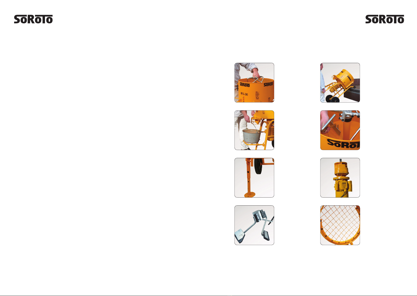
Rubber Blades
Ideal for mixes
containing
aggregates
Dust Liminator
Easily tted and for
limiting the exposure
to dust
Mixer Arms
Easily replaced
without tools
Loading
Easily loaded
onto and off a
vehicle
Bucket Stand
Sturdy and
easily folded
away
Maintenance
Easily done
Telescopic Legs
For easy adjust-
ment to preferred
working height
Motor
Available in 230V,
110V, 400V, Varios
and gasoline models
GB / 8 9 / GB
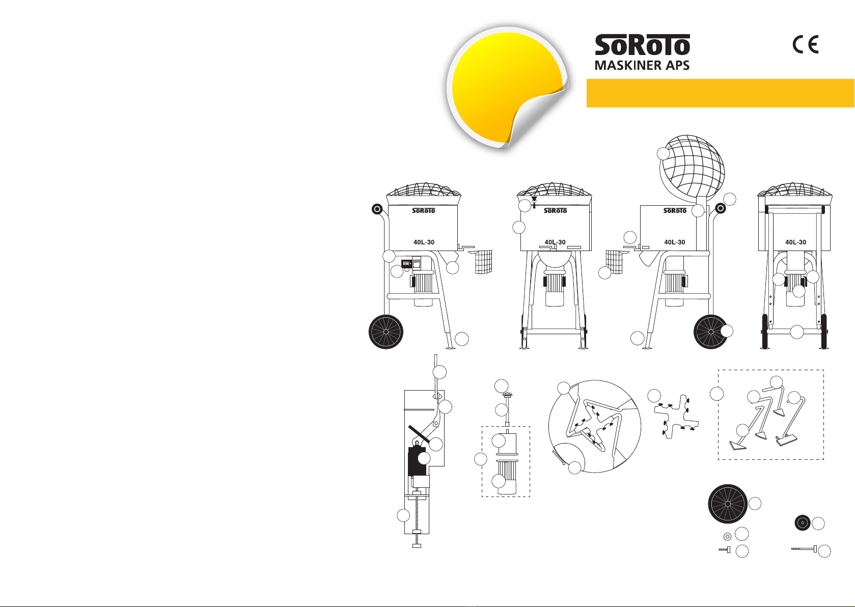
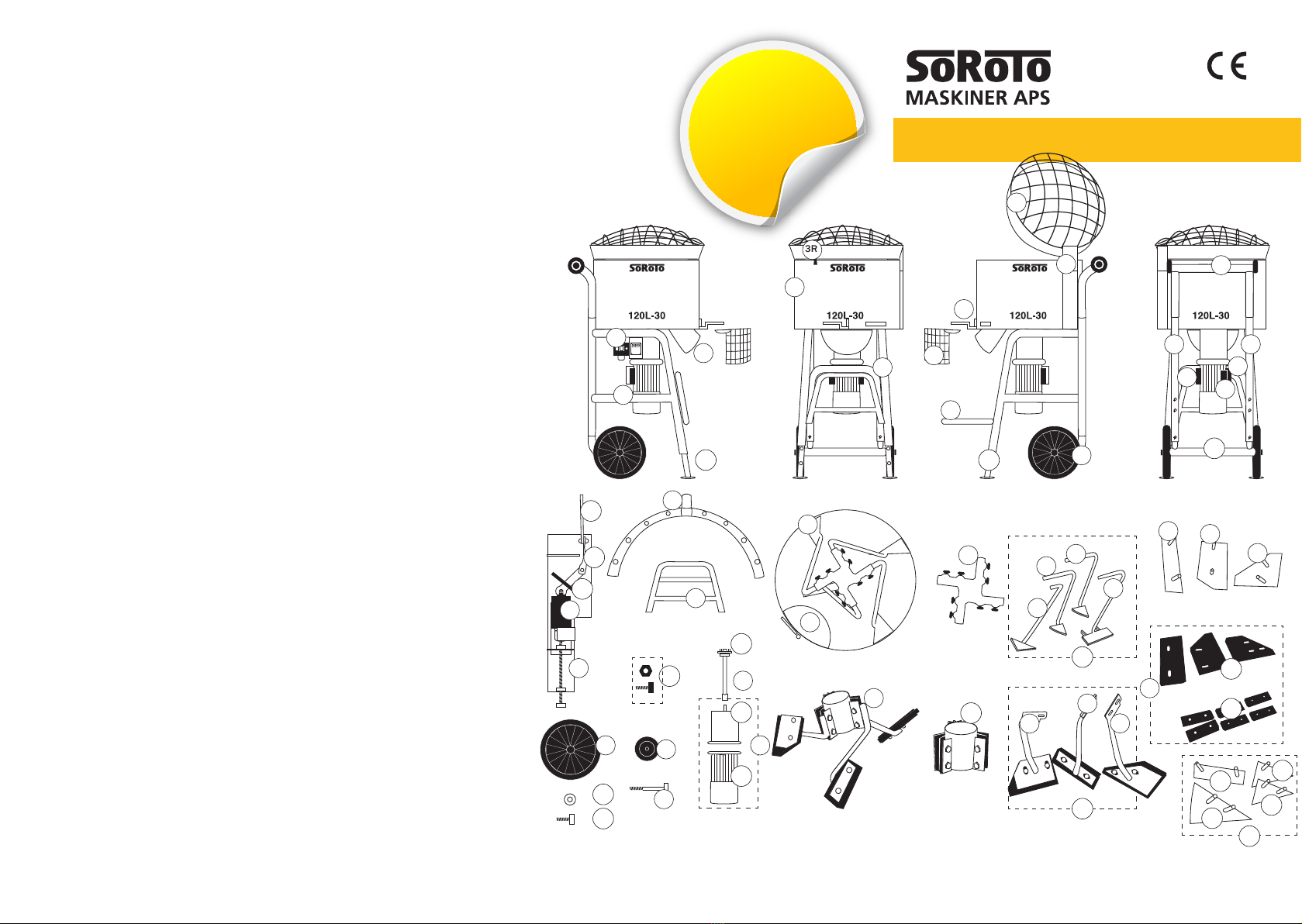
Pos.No. Description Spare Part No.
2 Grid lid (hinge 100 mm).........................................................40.002
3 Mixer drum incl. mixer gate, complete set............................40.003
3 R Rubber strap for grid lid .........................................................40.003R
4 Frame, complete w/wheels etc. ............................................40.004
4 A Frame, “Body” - excl. wheels and telescopic legs ................40.004A
5 Loading wheel (1 pc.), 80 mm, excl. bolt ..............................40.005
5 B Bolt (1 pc.) for 80 mm loading wheel....................................40.005B
6 Wheel (1 pc.), 300 mm, excl. bolt .........................................40.006
6 B Bolt (1 pc.) for 300 mm wheel...............................................40.006B
6 W Washer (1 pc.) for 300 mm wheel.........................................40.006W
7 Mixer gate incl. bolt etc ..........................................................40.007
8 Switch 9.5 Amp. w/thermal circuit breaker ..........................40.008
8 E Safety switch - by the grid lid .................................................40.008E
8 K Cassette for safety switch, complete.....................................40.008K
8 K1 Piece for safety switch, bended metal part ..........................40.008K1
8 K2 Piece for safety switch, twisted metal part. ..........................40.008K2
8 K3 Piece for safety switch, rubber part ......................................40.008K3
9 Mixer arm (1 pc.), Side (long).................................................40.009
9 A Mixer arm (1 pc.), Side (short)...............................................40.009A
10 Mixer arm (1 pc.), Side-base..................................................40.010
11 Mixer arm (1 pc.), Rake..........................................................40.011
12 Drive shaft, complete .............................................................40.012
12 A Spring pins, complete set of 12 incl. a jig.............................40.012A
13 Gear motor 0.75 kW, 1400/30 RPM., 230 V.......................40.013
13 G - Gear only...............................................................................40.013G
13 M - Motor only .............................................................................40.013M
14 Starting capacitor 125 µf.......................................................40.014
15 Operating capacitor 25 µf......................................................40.015
16 Phase capacitor 20 µf............................................................40.016
17 B Telescopic legs, rear...............................................................40.017B
17 L Teleskopic leg (1 pc.), front - left side ...................................40.017L
17 R Teleskopic leg (1 pc.), front - right side .................................40.017R
17 SB Bolt and nut (1 pair) for telescopic leg (1 pc.) ....................40.017SB
19 Safety grid by the mixer gate .................................................40.019
22 Mixer arms, 4 pcs., complete set ..........................................40.022
22 A Mixer arms, 4 pcs., wo/cross joint ........................................40.022A
30 Discharge chute (incl. nuts)...................................................40.030
44 Cross joint for mixer arms, steel............................................40.044
Spare Part List - 40 L, 230V
GB-07.11.16
3R
2
5
3
7
7
8
4
9
9A
6
6
5
6B 5B
10
11
12
44
8E
8E
8K
22
19
15
16
30
14
13
13M
17R 17L
13G
22A
17B
6W
8K3
8K2
8K1
12A
Spare Part List
for 40 L mixers,
110V, is available
online
GB / 10 11 / GB
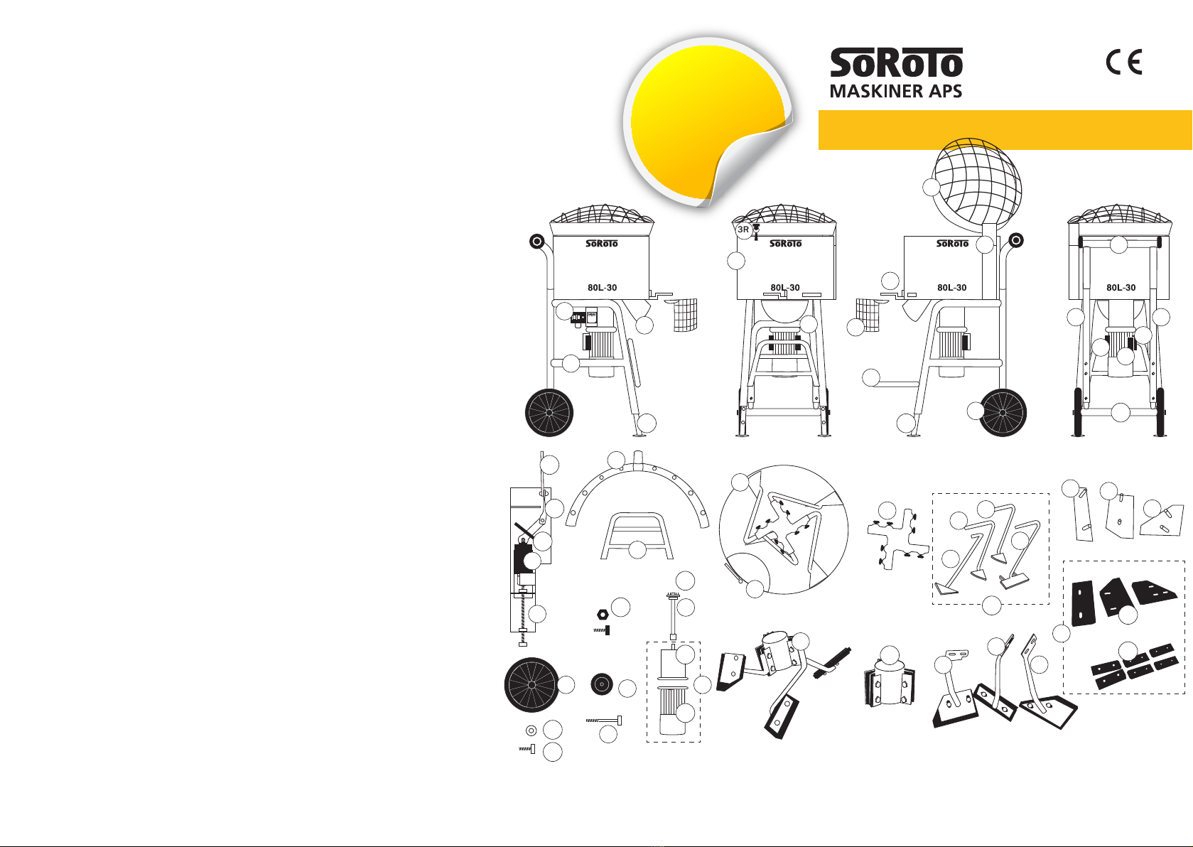
Pos. No. Description Art. No.
1 * Dust liminator ......................................................................... 80.001DL
2 Grid lid (hinge 100 mm)......................................................... 80.002
3 Mixer drum incl. mixer gate, complete set............................ 80.003
3 R Rubber strap - for grid lid ....................................................... 80.003R
4 Frame, complete w/wheels etc. ............................................ 80.004
4 B Bucket stand........................................................................... 80.004B
4 F Frame, front part (U-shape) ................................................... 80.004F
4 L Frame, left side part............................................................... 80.004L
4 R Frame, right side part............................................................. 80.004R
4 T Frame, top/rear part .............................................................. 80.004T
5 Loading wheel (1 pc), 80 mm, excl. bolt ............................... 80.005
5 B Bolt (1 pc.) for 80 mm loading wheel.................................... 80.005B
6 Wheel (1 pc.), 300 mm, excl. bolt ......................................... 80.006
6 B Bolt (1 pc.) for 300 mm wheel............................................... 80.006B
6 W Washer (1 pc.) for 300 mm wheel......................................... 80.006W
7 Mixer gate incl. bolt etc. ......................................................... 80.007
8 Switch 9.5 Amp. w/thermal circuit breaker .......................... 80.008
8 E Safety switch - by the grid lid ................................................. 80.008E
8 K Cassette for safety switch, complete..................................... 80.008K
8 K1 Piece for safety switch, bended metal part .......................... 80.008K1
8 K2 Piece for safety switch, twisted metal part. .......................... 80.008K2
8 K3 Piece for safety switch, rubber part ...................................... 80.008K3
9 Mixer arm (1 pc.), Side........................................................... 80.009
10 Mixer arm (1 pc.), Side-base.................................................. 80.010
11 Mixer arm (1 pc.), Rake.......................................................... 80.011
12 Drive shaft, complete ............................................................. 80.012
12 A Spring pins, complete set of 12 pins incl. a jig..................... 80.012A
13 Gear motor 1.1 kW, 1400/30 RPM, 230 V........................... 80.013
13 G - Gear only............................................................................... 80.013G
13 M - Motor only ............................................................................. 80.013M
14 Starting capacitor 125 µf....................................................... 80.014
15 Operating capacitor 25 µf...................................................... 80.015
16 Phase capacitor 20 µf............................................................ 80.016
17 B Telescopic legs, rear............................................................... 80.017B
17 L Telescopic leg, front - left side ............................................... 80.017L
17 R Telescopic leg, front - right side............................................. 80.017R
17 SB Bolt and nut (1 pair) for telescopic leg (1 pc.) .................... 80.017SB
19 Safety grid - by the mixer gate ............................................... 80.019
20 * Mixer arms w/rubber, 3 pcs., complete set.......................... 80.020
20 A Mixer arms w/rubber, 3 pcs., wo/cross joint........................ 80.020A
48 Mixer arm w/rubber, Rake ..................................................... 80.048
49 Mixer arm w/rubber, Side-base ............................................. 80.049
50 Mixer arm w/rubber, Side ...................................................... 80.050
21 Rubber parts (replacement set, complete)........................... 80.021
21 A Rubber parts (replacement set, blades only) ....................... 80.021A
21 B Rubber parts (replacement set, cross joint only) ................. 80.021B
22 Mixer arms, set of 4 pcs., complete ...................................... 80.022
22 A Mixer arms, set of 4 pcs., wo/cross joint.............................. 80.022A
30 Discharge chute (incl. nuts)................................................... 80.030
44 Cross joint for mixer arms, steel............................................ 80.044
47 Cross joint for mixer arms, rubber......................................... 80.047
51 Bracket for mixer blade, rubber, Rake .................................. 80.051
52 Bracket for mixer blade, rubber, Side-base .......................... 80.052
53 Bracket for mixer blade, rubber, Side.................................... 80.053
Spare part list - 80 L, 230V
GB-07.11.16
* OPTIONAL / ADDITOINAL EQUIPMENT
3
4T
4F 4L 4R
4
6
8
30
20
22
9
11
10
9
44
19
3R
8E
4B
4B
5
6
5B
1
2
47
8K1
21A
21B
6B
17SB
8K3
8K2
6W
17L
17B
17R
22A
13G
12A
13M
21
51
48
49 50
52
53
13
12
8E
8K
7
7
15
16
14
Spare Part List
for 80 L mixers,
110V, is available
online

GB / 12 13 / GB
Pos. No. Description Art. No.
1 * Dust liminator ......................................................................... 100.001DL
2 Grid lid (hinge 100 mm)......................................................... 100.002
3 Mixer drum incl. mixer gate, complete set............................ 100.003
3 R Rubber strap - for grid lid ....................................................... 100.003R
4 Frame, complete w/wheels etc. ............................................ 100.004
4 B Bucket stand........................................................................... 100.004B
4 F Frame, front part (U-shape) ................................................... 100.004F
4 L Frame, left side part............................................................... 100.004L
4 R Frame, right side part............................................................. 100.004R
4 T Frame, top/rear part .............................................................. 100.004T
5 Loading wheel (1 pc), 80 mm, excl. bolt ............................... 100.005
5 B Bolt (1 pc.) for 80 mm loading wheel.................................... 100.005B
6 Wheel (1 pc.), 300 mm, excl. bolt ......................................... 100.006
6 B Bolt (1 pc.) for 300 mm wheel............................................... 100.006B
6 W Washer (1 pc.) for 300 mm wheel......................................... 100.006W
7 Mixer gate incl. bolt etc. ......................................................... 100.007
8 Switch 16 Amp. w/thermal circuit breaker ........................... 100.008
8 E Safety switch - by the grid lid ................................................. 100.008E
8 K Cassette for safety switch, complete..................................... 100.008K
8 K1 Piece for safety switch, bended metal part .......................... 100.008K1
8 K2 Piece for safety switch, twisted metal part. .......................... 100.008K2
8 K3 Piece for safety switch, rubber part ...................................... 100.008K3
9 Mixer arm (1 pc.), Side........................................................... 100.009
10 Mixer arm (1 pc.), Side-base.................................................. 100.010
11 Mixer arm (1 pc.), Rake.......................................................... 100.011
12 Drive shaft, complete ............................................................. 100.012
12 A Spring pins, complete set of 12 pins incl. a jig..................... 100.012A
13 Gear motor 1.1 kW, 1400/30 RPM, 230 V........................... 100.013
13 G - Gear only............................................................................... 100.013G
13 M - Motor only ............................................................................. 100.013M
14 Starting capacitor 125 µf....................................................... 100.014
15 Operating capacitor 25 µf...................................................... 100.015
16 Phase capacitor 20 µf............................................................ 100.016
17 B Telescopic legs, rear............................................................... 100.017B
17 L Telescopic leg, front - left side ............................................... 100.017L
17 R Telescopic leg, front - right side............................................. 100.017R
17 SB Bolt and nut (1 pair) for telescopic leg (1 pc.) .................... 100.017SB
19 Safety grid - by the mixer gate ............................................... 100.019
20 * Mixer arms w/rubber, 3 pcs., complete set.......................... 100.020
20 A Mixer arms w/rubber, 3 pcs., wo/cross joint........................ 100.020A
48 Mixer arm w/rubber, Rake ..................................................... 100.048
49 Mixer arm w/rubber, Side-base ............................................. 100.049
50 Mixer arm w/rubber, Side ...................................................... 100.050
21 Rubber parts (replacement set, complete)........................... 100.021
21 A Rubber parts (replacement set, blades only) ....................... 100.021A
21 B Rubber parts (replacement set, cross joint only) ................. 100.021B
22 Mixer arms, set of 4 pcs., complete ...................................... 100.022
22 A Mixer arms, set of 4 pcs., wo/cross joint.............................. 100.022A
30 Discharge chute (incl. nuts)................................................... 100.030
44 Cross joint for mixer arms, steel............................................ 100.044
47 Cross joint for mixer arms, rubber......................................... 100.047
51 Bracket for mixer blade, rubber, Rake .................................. 100.051
52 Bracket for mixer blade, rubber, Side-base .......................... 100.052
53 Bracket for mixer blade, rubber, Side.................................... 100.053
Spare Part List - 100 L, 230V
GB-07.11.16
*OPTIONAL / ADDITIONAL EQUIPMENT
3
4T
4F 4L 4R
4
6
8
30
20
22
9
11
10
9
44
19
3R 8E
4B
4B
5
6
5B
1
2
47
8K1
21A
22A
21B
6B
17SB
8K3
8K2
6W
17L
17B
17R
13G
12A
13M
21
51
48
49 50
52
53
13
12
8E
8K
7
7
15
16
14
Spare Part List
for 100 L mixers,
110V, is available
online
GB / 14 15 / GB
Pos. No. Description Art. No.
1 Dust liminator................................................................................. 120.001DL
2 Grid lid (hinge 100 mm)................................................................. 120.002
3 Mixer drum incl. mixer gate, complete set ................................... 120.003
3 R Rubber strap - for grid lid............................................................... 120.003R
4 Frame, complete w/wheels etc..................................................... 120.004
4 B Bucket stand .................................................................................. 120.004B
4 F Frame, front part (U-shape)........................................................... 120.004F
4 L Frame, left side part ...................................................................... 120.004L
4 R Frame, right side part ....................................................................120.004R
4 T Frame, top/rear part...................................................................... 120.004T
5 Loading wheel (1 pc.), 80 mm, excl. bolt...................................... 120.005
5 B Bolt (1 pc.) for 80 mm loading wheel ........................................... 120.005A
6 Wheel (1 pc.), 300 mm, excl. bolt................................................. 120.006
6 B Bolt (1 pc.) for 300 mm wheel ...................................................... 120.006B
6 W Washer (1 pc.) for 300 mm wheel ................................................ 120.006W
7 Mixer gate incl. bolt etc.................................................................. 120.007
8 Switch 9,5 Amp. w/thermal circuit breaker and O-discharger.... 120.008
8 E Safety switch - by the grid lid......................................................... 120.008E
8 K Cassette for safety switch, complete ............................................ 120.008K
8 K1 Cassette for safety switch, bended metal part ............................ 120.008K1
8 K2 Cassette for safety switch, twisted metal part ............................. 120.008K2
8 K3 Cassette for safety switch, rubber part......................................... 120.008K3
12 Drive shaft ...................................................................................... 120.012
12 A Spring pins, complete set of 12 pins incl. a jig ............................ 120.012A
13 Gearmotor 1.1 kW, 1400/30 RPM, 230 V ................................... 120.013
13 G - Gear only....................................................................................... 120.013G
13 M - Motor only..................................................................................... 120.013M
14 Starting capacitor 125 µf .............................................................. 120.014
15 Operating capacitor 25 µf ............................................................. 120.015
16 Phase capacitor 20 µf ................................................................... 120.016
17 B Telescopic leg (1 pc.), rear............................................................. 120.017B
17 L Telescopic leg (1 pc.), front - left side ........................................... 120.017L
17 R Telescopic leg (1 pc.), front - right side......................................... 120.017R
17 SB Bolt and nut (1 pair) for telescopic leg (1 pc.).............................. 120.017SB
19 Safety grid - by the mixer gate....................................................... 120.019
20 * Mixer arms w/rubber, 3 pcs. complete set................................... 120.020
20 A Mixer arms w/rubber, 3 pcs., wo/cross joint ...............................120.020A
21 Rubber parts (replacement set, complete) .................................. 120.021
21 A Rubber parts (replacement set, blades only)............................... 120.021A
21 B Rubber parts (replacement set, cross joint only)......................... 120.021B
23 Mixer arms, set of 4 pcs., complete set........................................120.023
23 A Mixer arms, set of 4 pcs., wo/cross joint ..................................... 120.023A
24 Mixer arm (1 pc.), Side................................................................... 120.024
25 Mixer arm (1 pc.), Side-base ......................................................... 120.025
26 Mixer arm (1 pc.), Rake .................................................................120.026
24 A Mixer blade, seperate, Side........................................................... 120.024A
25 A Mixer blade, seperate, Side-base ................................................. 120.025A
26 A Mixer blade, seperate, Rake.......................................................... 120.026A
27 Mixer blades, steel, complete set (4 pcs., incl. nuts) .................. 120.027
30 Discharge chute, incl. bolts ........................................................... 120.030
44 Cross joint for mixer arms, steel, incl. bolts .................................120.044
47 Cross joint for mixer arms, rubber, incl. brackets and bolts........ 120.047
51 Bracket for mixer blade, rubber, Rake.......................................... 120.051
52 Bracket for mixer blade, rubber, Side-base.................................. 120.052
53 Bracket for mixer blade, rubber, Side ........................................... 120.053
Spare Part List - 120 L, 230V
GB-07.11.16
*OPTIONAL / ADDITIONAL EQUIPMENT
3
4T
4F
4L 4R
4
6
8
30
20
23
24
26
26
24
44
19
3R
8E
4B
4B
5
6
5B
1
2
47
8K1
21A
21B
24A
24A
25A
26A
6W
17SB
8K3
8K2
6B
17L
17B
17R
13A
12A
13B
21
51
48
49 50
52
53
13
12
8E
8K
7
7
15
16
14
27
23A
20A
Spare Part List
for 120 L mixers,
110V, is available
online

GB / 16 17 / GB
MANUAL APPLIES TO
SoRoTo 200L and 300L
APPLICATION
The SoRoTo Forced Action Mixers are ideal for mixing all kinds of mate-
rials used in the building industry, as well as mixing tasks where high
demand are required.
When mixing materials containing aggregates, we recommend using
the SoRoTo mixer arms with rubber blades.
BEFORE USE
Before starting the mixer, the telescopic legs must be positioned for the
right height for draining into a bucket or wheelbarrow.
The easiest way for adjusting the legs, is to lay the mixer down, so it
rests on all four wheels. The legs are released and locked with the t-
ted lock splits/bolts.
BEFORE CONNECTING TO POWER SUPPLY
Before the power is connected, the mixer arms must be set in place,
and the lid must be closed.The safety grid in front of the mixer gate
must be attached at all times.
For own safety always follow the instruction listed above before use.
OPERATING THE SoRoTo FORCED ACTION MIXER
The motor protection unit in this mixer is equipped with a bult in re-
verse locking system. This prevents the motor from running in reverse.
If the extension lead does not have a neutral (i.e. 4 core cable) the
machine will not start.
So, before you start mixing please do as follows,
1) Push the green START button
2) Notice if the mixer arms run clockwise
3) In the event that the mixer arms run counterclockwise, please
adjust to clockwise direction by following these instructions:
• It is essential the neutral wire is part of the cable (5 core) as
well as the electric socket supplying power to the motor
(i.e. wall wall socket, switchboard)
• The phases of the reverse locking system may be easily
adjusted by inserting a atheaded screwdriver into the
slot on the red plug and turning 180 degrees
NOTE
The mixer remains non-operational if the lid is open.
Close the lid and lock it into place using the rubber strap. Start the
mixer by pressing the green START button on the protective motor
switch. Pour the required material into the drum and add liquid.
The protective motor switch has a zero voltage releaser. In case of
power failure, the mixer must be restarted. For safety reasons, the
mixer will not start if the lid is open.
NOTE
Never put your hand or any object into the machine when the power
is connected.
When the material has reached the desired consistency and the
mixing motion is nished, the mixer drum is emptied by opening the
mixer gate. The drum should be emptied right after mixing. Please
observe that the material may set in the mixer drum if left too long.

GB / 18 19 / GB
SAFETY
When using an extension cable, please observe the following,
• Never use a longer cable than necessary.
• Always use a cable with a minimum dimension of 1 mm2.
• Never use the cable when it is rolled up. Always roll it out completely.
When mixing materials that emit unpleasant or dangerous vapours
and/or dust, a dust liminator is recommended.
TECHNICAL DATA
Model 200L/30
Motor: 400V – 2.2 kW – 50 Hz
W/L/H: 60*60*85 cm
Mixing capacity: 200 litres
Weight: 175 kg (empty).
LAeq<75dB(A) with mortar.
Model 300L/30
Motor: 400V – 3.0 kW – 50 Hz
W/L/H: 60*75*106 cm
Mixing capacity: 270 litres
Weight: 281 kg (empty).
LAeq<75dB(A with mortar.
CONTACT DETAILS
Production Unit / Technical Support
Egegårdsvej 4-6
DK-2610 Rødovre
Tel. +45 36 72 78 00
teknik@soroto.dk
NOTE
The safety grid should be in front of the output gate at all times. If the
machine is jammed, e.g. by larger stones, ensure that the plug is discon-
nected from the protective motor switch, before removing the obstruc-
tion. Do not put your ngers or any object up through the mixer gate.
CLEANING / MAINTENANCE
Before cleaning the mixer, the plug must be removed from the socket.
Open the lid and lift the mixer arms off the axle. The mixer arms are
easily removed without using tools. Firstly wash the mixer arms and the
entire mixer drum using water.
NOTE
While the mixer arms are disconnected from the axle tower, make sure
that neither water nor dust etc. enter the axle tower.
When cleaning has ended, place the mixer arms onto the axle and
close the lid.
TRANSPORT
When transporting the SoRoTo 200 L Forced Action Mixer it is recom-
mended that the mixer be placed on the four wheels, the lid closed and
locked - using the rubber strap.
When transporting the SoRoTo 300 L Forced Action Mixer with the trac-
tion bar, the traction bar is locked with 2 pin bolts. The traction bar can
now be attached to a vehicle. The 300 L mixer may only be transported
locally and at very low speed. During transport, the lid must be closed
and locked using the rubber strap. When transporting the SoRoTo 300
L on a truck, the mixer may be lifted onto the truck with the help of e.g.
a pallet truck. Please observe that the wheels must be blocked during
transport.
Administration / Order Processing
Ved Damhussøen 24
DK-2720 Vanløse
Tel. +45 36 72 75 00
soroto@soroto.dk
GB / 20 21 / GB
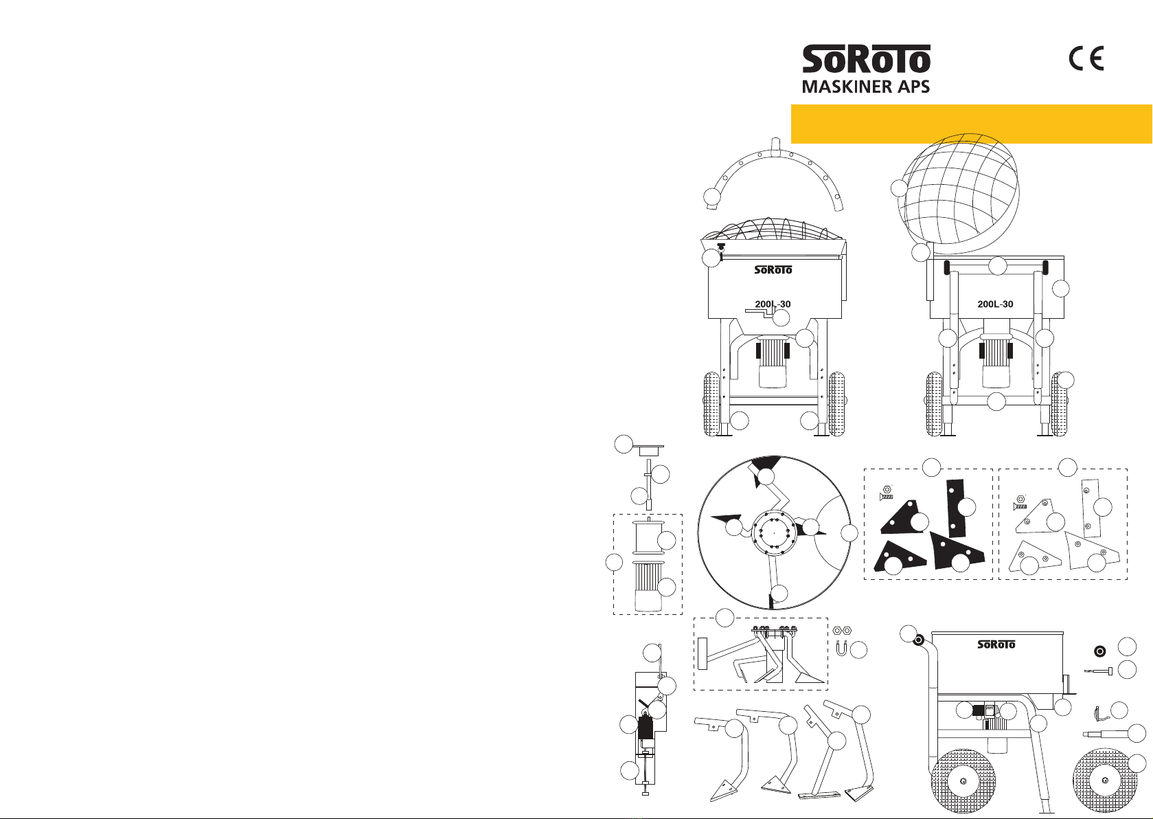
Pos. No. Description Art. No.
1 * Dust liminator ....................................................................................200.001DL
2 Grid lid (hinge 100 mm)....................................................................200.002
3 Mixer drum incl. mixer gate, complete set....................................... 200.003
3 R Rubber strap - for grid lid .................................................................. 200.003R
4 Frame, complete w/wheels etc. ....................................................... 200.004
4 F Frame, front part (U-shape) .............................................................. 200.004F
4 L Frame, left side part..........................................................................200.004L
4 R Frame, right side part........................................................................ 200.004R
4 T Frame, top/rear part .........................................................................200.004T
5 Loading wheel (1 pc), 80 mm, excl. bolt .......................................... 200.005
5 B Bolt (1 pc.) for 80 mm loading wheel...............................................200.005B
6 Wheel (1 pc.), 400 mm, excl. bolt ....................................................200.006
6 A Axle (1 pc.) for 400 mm wheel..........................................................200.006A
7 Mixer gate incl. bolt etc ..................................................................... 200.007
8 Switch 9.5 Amp. w/therm. circuit breaker, phase adjust. system..200.008
8 E Safety switch - by the grid lid ............................................................200.008E
8 K Cassette for safety switch, complete................................................200.008K
8 K1 Piece for safety switch, bended metal part ..................................... 200.008K1
8 K2 Piece for safety switch, twisted metal part. ..................................... 200.008K2
8 K3 Piece for safety switch, rubber part .................................................200.008K3
9 Outlet plug 1 x 230V, 16 amp...........................................................200.009
10 Top disc, separate (wo/U-bolts)........................................................200.010
11 U-bolt (1 pc.) for securing the top disc (8 pcs. in total), incl. nut ... 200.011
12 Drive shaft, complete ........................................................................ 200.012
13 Gear motor 2.2 kW, 1400/30 RPM, 400 V ..................................... 200.013
13 G - Gear only..........................................................................................200.013G
13 M - Motor only ........................................................................................200.013M
14 Strips (1 pc.) for axle and telescopic legs, dia. ø55mm..................200.014
17 B Telescopic leg (1 pc.), rear ................................................................ 200.017B
17 L Telescopic leg, front - left side ..........................................................200.017L
17 R Telescopic leg, front - right side........................................................200.017R
20 Mixer arm w/rubber blade, Side.......................................................200.020
21 Mixer arm w/rubber blade, Mid-base...............................................200.021
22 Mixer arm w/rubber blade Tower-base ............................................ 200.022
23 Mixer arm w/rubber blade, Side-base .............................................200.023
24 Mixer arms w/rubber blades, complete set incl. top disc............... 200.024
24 A Mixer arms w/rubber blades, complete set excl. top disc..............200.024A
20 B Mixer arm wo/rubber blade, Side.....................................................200.020B
21 B Mixer arm wo/rubber blade, Mid-base ............................................ 200.021B
22 B Mixer arm wo/rubber blade, Tower-base ......................................... 200.022B
23 B Mixer arm wo/rubber blade, Side-base ...........................................200.023B
24 B Mixer arms wo/rubber blade, complete set excl. top disc..............200.024B
20 R Blade, rubber part, Side.................................................................... 200.020R
21 R Blade, rubber part, Mid-base............................................................200.021R
22 R Blade, rubber part, Tower-base ........................................................200.022R
23 R Blade, rubber part, Side-base...........................................................200.023R
24 R Blade, rubber parts, complete replacement set ............................. 200.024R
20 S* Blade, Hardox steel part, Side..........................................................200.020S
21 S* Blade, Hardox steel part, Mid-base.................................................. 200.021S
22 S* Blade, Hardox steel part, Tower-base............................................... 200.022S
23 S* Blade, Hardox steel part, Side-base.................................................200.023S
24 S* Blade, Hardox steel parts, complete replacement set....................200.024S
29 Bearing for drive shaft ...................................................................... 200.029
30 Discharge chute, incl. nuts ...............................................................200.030
Spare part list - 200 L, 400V
GB-07.11.16
*OPTIONAL / ADDITIONAL PARTS
1
2
5
6
3
7
7
8
4
930 14
12
23
22
20
21
20B
21B
8K1
8K2
8K3
8E
8K
22B
23B
11
13M
17R 17L
17B
10
29
3R
5
6
6A
5B
13G
8E
4T
4R4L4F
24R
24
24S
21R 21S
22R 22S
23R 23S
20R 20S
13
GB / 22 23 / GB
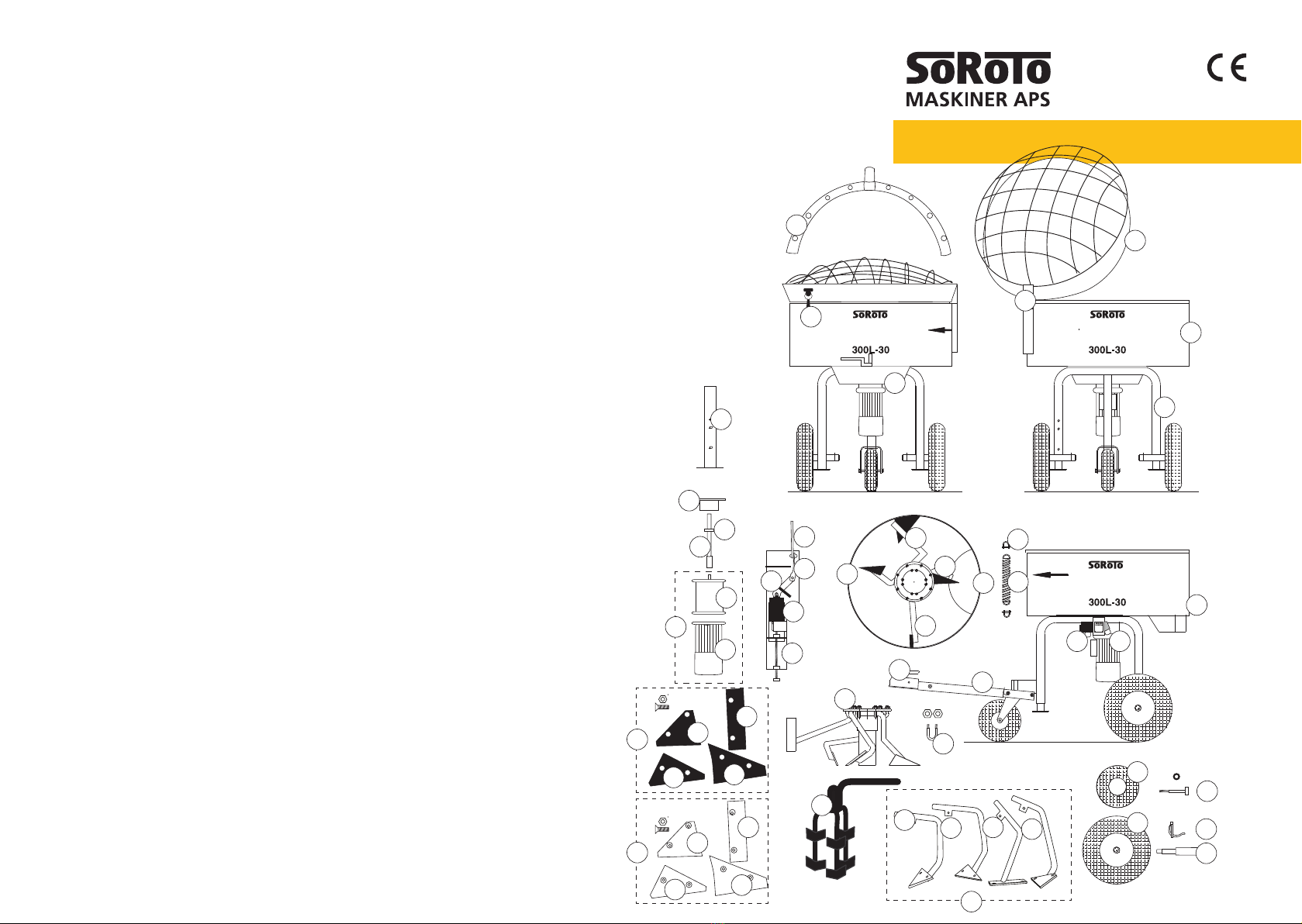
Pos.No Description Art. No.
1 * Dust liminator......................................................................................... 300.001DL
2 Grid lid (hinge 100 mm)......................................................................... 300.002
3 Mixer drum incl. mixer gate, complete set ...........................................300.003
3 R Rubber strap - for grid lid....................................................................... 300.003R
4 Frame, complete w/wheels etc............................................................. 300.004
5 Wheel (1 pc.), 250 mm, excl. bolt.........................................................300.005
5 A Bolt, 10x120 mm, for 250 mm wheel, incl. nut................................... 300.005A
6 Wheel (1 pc.), 400 mm, excl. bolt.........................................................300.006
6 A Axle (1 pc.) for 400 mm wheel .............................................................. 300.006A
7 Mixer gate incl. bolt etc.......................................................................... 300.007
8 Switch 9.5 Amp. w/therm. circuit breaker, phase adj. system ........... 300.008
8 E Safety switch - by the grid lid.................................................................300.008E
8 K Cassette for safety switch, complete .................................................... 300.008K
8 K1 Piece for safety switch, bended metal part.......................................... 300.008K1
8 K2 Piece for safety switch, twisted metal part........................................... 300.008K2
8 K3 Piece for safety switch, rubber part ...................................................... 300.008K3
9 Outlet plug 1 x 230V 16 Amp................................................................ 300.009
10 Top disc, separate (w/U-bolts)............................................................... 300.010
10 A Top disc, separate (wo/U-bolts and nuts)............................................. 300.010A
11 U-bolt (1 pc.) for securing top disc (8 pcs. needed in total) ................ 300.011
12 Drive shaft, complete............................................................................. 300.012
13 Gear motor 3.0 kW, 1400/30 RPM, 400V ........................................... 300.013
13 G - Gear only............................................................................................... 300.013G
13 M - Motor only............................................................................................. 300.013M
14 Strips (1 pc.) for the axle and telescopic legs, dia. ø55mm................ 300.014
15 Telescopic leg (1 pc.) .............................................................................300.015
17 * Pole excl. globe coupling ....................................................................... 300.017
17 A Stud bolt for pole.................................................................................... 300.017A
18 * Globe coupling incl. bolt and nut .......................................................... 300.018
19 Spring for grid lid.................................................................................... 300.019
19 A D-shackle bolt for spring........................................................................ 300.019A
20 Mixer arm w/rubber blade, Side ........................................................... 300.020
21 Mixer arm w/rubber blade, Mid-base ................................................... 300.021
22 Mixer arm w/rubber blade, Tower-base................................................ 300.022
23 Mixer arm w/rubber blade, Side-base.................................................. 300.023
24 Mixer arms w/rubber blade, complete set incl. top disc ..................... 300.024
24 A Mixer arms w/rubber blade, complete set excl. top disc .................... 300.024A
20 B Mixer arm wo/rubber blade, Side ......................................................... 300.020B
21 B Mixer arm wo/rubber blade Mid-base.................................................. 300.021B
22 B Mixer arm wo/rubber blade, Tower-base.............................................. 300.022B
23 B Mixer arm wo/rubber blade, Side-base................................................ 300.023B
20 R Blade, rubber part, Side ........................................................................ 300.020R
21 R Blade, rubber part, Mid-base ................................................................ 300.021R
22 R Blade, rubber part, Tower-base............................................................. 300.022R
23 R Blade, rubber part, Side-base ............................................................... 300.023R
24 R Blades, rubber part, complete replacement set ................................. 300.024R
20 S* Blade, Hardox steel, Side.......................................................................300.020S
21 S* Blade, Hardox steel, Mid-base .............................................................. 300.021S
22 S* Blade, Hardox steel, Tower-base ........................................................... 300.022S
23 S* Blade, Hardox steel, Side-base ............................................................. 300.023S
24 S* Blades, Hardox steel, complete replacement set ................................ 300.024S
25 * TURBO mixer arm (for mixing builder’s mortar) ** .............................300.025
29 Bearing for drive shaft ........................................................................... 300.029
30 Discharge chute ................................................................................... 300.030
Spare part list - 300 L, 400V
GB-07.11.16
* OPTIONAL / ADDITIONAL PARTS
** Pos.No. 21 is replaced by pos.no. 25
8K3
9
10
11
12
29
13G
13M
30
17
18
19
19A
20
21 22
23
20R
20S 20B
21B
22R
22S
22B
23R
23S
23B
25
21R
21S
15
10A
8K2
8K1
8K
8E
8E
8
7
7
6A
14
5A
5
6
4
3
3R
2
1
24S
24R
24A
13
EU Declaration of Conformity
Annex II.A of the Machinery Directive
Manufacturer: SoRoTo Maskiner ApS
Address: Ved Damhussøen 24, 2720 Vanløse, DENMARK
Product: Forced Action Mixers
Model: 40L-30, 65 light, 80L-30, 100L-30, 120L-30,
200L-30 and 300L-30
Manufactured: From 2015 and onwards
We hereby declare that the SoRoTo Forced Action Mixers are manu-
factured in conformity with the stipulation containted in COUNCIL
DIRECTIVE No. 2006/42/EC on the approximation of the laws of member
states on machine, including subsequent modifications, with special re-
gard to Annex I of the directive on important safety and health require-
ments in connection with the design and manufacture of machines.
Furthermore, we declare that the SoRoTo Forced Action Mixers are
manufactured in conformity with the following harmonised standard,
EN 12151:2007
05.04.2016
Vanløse, DENMARK
________________________
Ronny Andersen
CEO
Original
administration
Ved Damhussøen 24
DK-2720 Vanløse
Tel.: +45 36 72 75 00
Fax: +45 38 71 36 16
production
Egegårdsvej 4-6
DK-2610 Rødovre
Tel.: +45 36 72 78 00
Fax: +45 36 72 75 90
soroto@soroto.dk
www.soroto.com
Further details:
www.soroto.com
or scan the QRC
This manual suits for next models
6
Table of contents
Other SoRoTo Mixer manuals


