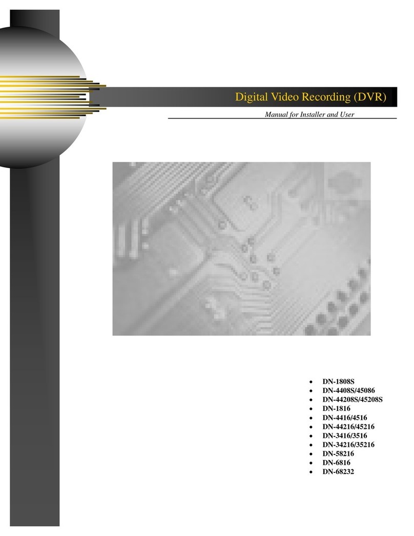
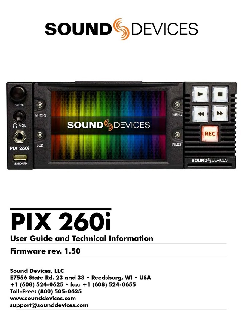
Sound Devices PIX 260i Manual

PIX 260i
User Guide and Technical Information
Firmware rev. 1.04
Sound Devices, LLC
E7556 State Rd. 23 and 33 • Reedsburg, WI • USA
+1 (608) 524-0625 • fax: +1 (608) 524-0655
Toll-Free: (800) 505-0625
www.sounddevices.com


PIX 260i User Guide and Technical Information
Introduction ..................................2
Manual Conventions ................................2
Video Mode and Audio Mode..........................2
Panel Descriptions ............................4
Front Panel........................................4
Rear Panel ........................................5
PIX-CADDY 2 (Optional) .............................7
Menu and Navigation ..........................8
LCD .............................................8
Main View.........................................8
On-screen Display ..................................8
Menu ...........................................10
Audio Screen .....................................10
File List..........................................11
File Details .......................................13
Inputs and Outputs ...........................14
Video Inputs ......................................14
HDMI ...........................................14
SDI ............................................14
Video Outputs ....................................14
Audio Inputs .....................................15
Analog Audio Inputs ................................15
XLR (1-2) ........................................15
DB25 (1-8) .......................................15
Digital Audio Inputs ................................15
HDMI / SDI Embedded Audio ........................15
AES3 ...........................................15
Dante Audio Inputs.................................16
Dante Redundancy ................................17
Sample Rate Converters ............................17
Choosing Audio Sources ............................17
Input Level Control .................................17
Input Delay Control ................................18
Audio Outputs ....................................18
Analog Audio Outputs ..............................18
Digital Audio Outputs (AES/HDMI).....................18
Dante Audio Outputs ...............................18
SDI Audio Outputs .................................18
Headphone Output.................................18
Ethernet ....................................19
Video Monitoring Features .....................20
Exposure Assist ...................................20
False Color.......................................20
Zebras ..........................................21
Focus Assist......................................22
Peaking .........................................22
Edge Enhance ....................................23
Zoom ...........................................24
Flip Display.......................................24
Recording...................................25
Selecting Video File Resolution and Frame Rate..........26
Progressive Segmented Frames (PsF) .................26
Selecting a Video Codec ............................26
Interruption of Signal During Recording.................27
Alignment of Audio and Video ........................27
Audio Track Arming ................................27
Audio Mode ......................................27
Polyphonic or Monophonic WAV Files ..................27
Audio Mode Settings ...............................28
F Sampling Rate Modes. . . . . . . . . . . . . . . . . . . . . . . . . . . . . 28
48.048k and 48.048kF ..............................28
Fostex DV40......................................29
47.952k and 47.952kF ..............................29
Video Scaling and Frame Rate Conversion .......29
3:2 Pulldown Removal ..............................30
Up and Down Conversion ...........................30
Down-Conversion..................................31
Up-Conversion ....................................32
Playback ....................................33
Playback Operation ................................33
Fast Forward and Rewind ...........................33
File Skip .........................................33
Shuttle Playback Mode. . . . . . . . . . . . . . . . . . . . . . . . . . . . . . 34
Cue Marker ......................................34
Cue Marker Looping................................35
Play List .........................................35
Playback Mode....................................36
Playback Rate of Audio Files .........................37
Non-Native File Playback ............................37
Exporting QT Files for 260i Playback...................37
Playing Back Files on a Computer ....................37
Synchronization and Timecode .................38
Sync Reference ...................................39
Video Mode Synchronization .........................39
Audio Mode Synchronization .........................39
Timecode Reader. . . . . . . . . . . . . . . . . . . . . . . . . . . . . . . . . . 39
Internal Ambient® Lockit: Timecode Generator with Sync Out40
Setting the Sync Out ...............................40
Timecode Modes ..................................40
Freerun Timceode Mode ............................40
Record Run Timecode Mode .........................40
External Timecode Mode ............................41
Timecode Frame Rate ..............................41
Timecode Input Sources ............................41
Timecode BNC....................................41
SDI or HDMI Input Embedded Timecode................41
Synchronization/Timecode Examples ..................41
Single Video Camera, no Genlock .....................41
Single Camera with Genlock Input, Genlocked from PIX....42
Multiple Cameras with Genlock Input, all Genlocked from a Single
PIX ............................................42
Camera #1 to PIX #1, Camera #2 to PIX #2, No Genlock ..43
Camera to PIX with Word Clock Connection to Audio Recorder43
External Control..............................44
RS422 ..........................................44
PIX Grouping .....................................44
Group Transport ...................................44
Non-Grouping Settings and Functions..................44
Web Interface - PIXNET.............................44
PIXNET All Units Page..............................45
PIXNET Unit Page .................................46
PIXNET Unit Page Main View and Menu Tabs............47
Main View........................................47
Clips Menu .......................................47
File Storage Menu .................................47
Video Menu ......................................47
Audio Menu ......................................48
TC Menu ........................................48
OSD Menu .......................................48
Table of Contents

PIX 260i User Guide and Technical Information
v. 1.04 Features and specifications are subject to change. Visit www.sounddevices.com for the latest documentation.
Remote Menu.....................................48
Network Menu ....................................48
System Menu .....................................48
Triggering Recording from External Timecode............48
Triggering Recording from SDI Flag Bits ................49
GPIO (General Purpose Input / Output).................49
USB Keyboard ....................................50
Storage and File Management ..................51
Storage..........................................51
PIX-CADDY ......................................51
e S ATA ...........................................51
Supported Storage Devices ..........................51
Formatting .......................................52
Drive Modes......................................52
Record Mode (Simultaneous or Sequential) .............52
Metadata ........................................53
CamID ..........................................53
Reel ............................................53
Clip.............................................53
Scene/Shot. . . . . . . . . . . . . . . . . . . . . . . . . . . . . . . . . . . . . . . 53
Ta k e ............................................53
Audio Track Name (Audio Only) .......................54
File Management ..................................54
File Size Limit.....................................54
File Naming ......................................54
RED File Format ..................................54
Arri File Format ...................................55
Folder Structure ...................................55
Deleting a File ....................................55
Transferring Files ..................................55
USB, Firewire, Thunderbolt ..........................55
Ethernet File Transfer (Samba) .......................56
Setup Management and Firmware Upgrades ......58
Saving and Loading Setup Files ......................58
Custom Default Settings and Setup Menu Option Visibility ..58
Factory Restore ...................................60
Firmware Upgrades ................................60
Setup Menu Options ..........................62
Video/Audio Mode .................................62
File Storage ......................................62
Video ...........................................63
Audio ...........................................64
Timecode/Sync ...................................66
LCD Monitor......................................67
On-Screen Display .................................68
Remote Control ...................................68
Network .........................................69
System ..........................................69
Quick Setup ......................................70
Button Shortcuts .............................71
Connector Pin Assignments ...................72
Appendix A - Supported Files ..................74
Specifications - PIX 260i .......................75
SDI .............................................75
HDMI ...........................................75
Video Input Resolutions / Rates.......................75
Video Codecs and Files .............................75
Up/Down/Cross Conversion ..........................75
Frame Rate Conversion .............................75
LCD ............................................75
Audio Recording...................................75
Analog Audio .....................................76
Digital Audio ......................................76
File Storage ......................................76
Timecode and Sync ................................76
Control ..........................................77
Keyboard ........................................77
Power ...........................................77
Physical .........................................77
PIX 260i CE Declaration of Conformity ...........78
CE - CISPR Publication Dates ..................79
Software License ............................80
Warranty and Technical Support ................81
Warranty & Service ................................81
Technical Support / Bug Reports .....................81

PIX 260i User Guide and Technical Information
1
Copyright Notice and Release
All rights reserved. No part of this publication may be reproduced, stored in a retrieval system, or transmitted in any form or by any
means, electronic, mechanical, photocopying, recording, or otherwise, without the expressed written permission of SOUND DEVICES,
LLC. SOUND DEVICES is not responsible for any use of this information.
Microsoft Windows is a registered trademark of Microsoft Corporation. Macintosh, OSX, and ProRes are registered trademarks of Apple,
Inc. DNxHD is a registered trademark of Avid, Inc. Other product and company names mentioned herein may be the trademarks of their
respective owners.
PIX 260i, and the sound waves logo are registered trademarks of Sound Devices, LLC.
Limitation of Liability
LIMITATION ON SOUND DEVICES’ LIABILITY. SOUND DEVICES, LLC SHALL NOT BE LIABLE TO THE PURCHASER OF THIS
PRODUCT OR THIRD PARTIES FOR DAMAGES, LOSSES, COSTS, OR EXPENSES INCURRED BY PURCHASER OR THIRD PAR-
TIES AS A RESULT OF: ACCIDENT, MISUSE, OR ABUSE OF THIS PRODUCT OR UNAUTHORIZED MODIFICATIONS, REPAIRS,
OR ALTERATIONS TO THIS PRODUCT, OR FAILURE TO STRICTLY COMPLY WITH SOUND DEVICES, LLC’S OPERATING AND
INSTALLATION INSTRUCTIONS. TO THE FULLEST EXTENT PERMITTED BY LAW, SOUND DEVICES SHALL HAVE NO LIABILITY
TO THE END USER OR ANY OTHER PERSON FOR COSTS, EXPENSES, DIRECT DAMAGES, INCIDENTAL DAMAGES, PUNITIVE
DAMAGES, SPECIAL DAMAGES, CONSEQUENTIAL DAMAGES OR OTHER DAMAGES OF ANY KIND OR NATURE WHATSOEVER
ARISING OUT OF OR RELATING TO THE PRODUCTS, THESE TERMS AND CONDITIONS OR THE PARTIES’ RELATIONSHIP,
INCLUDING, WITHOUT LIMITATION, DAMAGES RESULTING FROM OR RELATED TO THE DELETION OR OTHER LOSS OF AUDIO
OR VIDEO RECORDINGS OR DATA, REDUCED OR DIMINISHED AUDIO OR VIDEO QUALITY OR OTHER SIMILAR AUDIO OR
VIDEO DEFECTS ARISING FROM, RELATED TO OR OTHERWISE ATTRIBUTABLE TO THE PRODUCTS OR THE END USER’S USE
OR OPERATION THEREOF, REGARDLESS OF WHETHER SUCH DAMAGES ARE CLAIMED UNDER CONTRACT, TORT OR ANY
OTHER THEORY. “CONSEQUENTIAL DAMAGES” FOR WHICH SOUND DEVICES SHALL NOT BE LIABLE SHALL INCLUDE, WITH-
OUT LIMITATION, LOST PROFITS, PENALTIES, DELAY DAMAGES, LIQUIDATED DAMAGES AND OTHER DAMAGES AND LIABILI-
TIES WHICH END USER SHALL BE OBLIGATED TO PAY OR WHICH END USER OR ANY OTHER PARTY MAY INCUR RELATED TO
OR ARISING OUT OF ITS CONTRACTS WITH ITS CUSTOMERS OR OTHER THIRD PARTIES. NOTWITHSTANDING AND WITHOUT
LIMITING THE FOREGOING, IN NO EVENT SHALL SOUND DEVICES BE LIABLE FOR ANY AMOUNT OF DAMAGES IN EXCESS
OF AMOUNTS PAID BY THE END USER FOR THE PRODUCTS AS TO WHICH ANY LIABILITY HAS BEEN DETERMINED TO EXIST.
SOUND DEVICES AND END USER EXPRESSLY AGREE THAT THE PRICE FOR THE PRODUCTS WAS DETERMINED IN CONSID-
ERATION OF THE LIMITATION ON LIABILITY AND DAMAGES SET FORTH HEREIN AND SUCH LIMITATION HAS BEEN SPECIFI-
CALLY BARGAINED FOR AND CONSTITUTES AN AGREED ALLOCATION OF RISK WHICH SHALL SURVIVE THE DETERMINATION
OF ANY COURT OF COMPETENT JURISDICTION THAT ANY REMEDY HEREIN FAILS OF ITS ESSENTIAL PURPOSE.

PIX 260i User Guide and Technical Information
v. 1.04 Features and specifications are subject to change. Visit www.sounddevices.com for the latest documentation.
2
Introduction
The PIX 260i is a rack-mountable, production video recorder with extensive audio and video pro-
cessing capabilities. The foundation of the PIX 260i is hardware-based, 10-bit video up/down/cross
conversion, and hardware-based encoding to Apple ProRes and Avid DNxHD codecs (both at up
to 12 bit 4:4:4). These features allow for fast, reliable acquisition of video (at any standard HD or
SD resolution and frame rate) and audio (up to 32 tracks from Analog, AES, HDMI, SDI, or Dante
sources) to ready-for-edit, industry standard Quicktime .mov les.
Files are recorded simultaneously on (up to) 4 separate, 2.5” SSD storage devices via two front panel
PIX-CADDY slots and two rear panel eSATAp connections. This redundancy in local, removable
storage devices, coupled with standard, Ethernet-based le transfer features further reduces steps in
the production workow. Gigabit Ethernet network ports enable remote access to recorded les and
the ability to transfer them quickly into a post-production environment.
Full-featured precision timecode and sync reference I/O using Ambient Lockit core technology is
provided to allow tight synchronization with external equipment in complex multi-machine congu-
rations. The PIX 260i supports various external control options: RS422, GPIO, SDI ags, Timecode
triggering, and an embedded web server for network-based remote control.
This User Guide details installation and operation of the PIX 260i. This User Guide corresponds to
PIX 260i rmware version 1.040. User Guide revisions are released at the same time as rmware
updates and available online:
hp://www.sounddevices.com/products/pix260i/downloads/
Manual Conventions
Several formaing features have been included to make navigating the guide easier.
• Setup Menu items are indicated with this text: [Menu Category - Parameter], where the menu
category is one of the items in the list displayed when the Menu buon is pushed, and the
parameter is an item in the list displayed when that category is selected (by pushing in on the
Control Knob).
• Terms that refer to specic controls or functions (such as Control Knob, Menu Buon, Setup
Menu, etc) are capitalized. These terms are described elsewhere in this user guide (see the Panel
Descriptions section).
• Blue italicized text references sections of the user guide containing contextually relevant
information.
Video Mode and Audio Mode
Throughout this User Guide, the terms Video Mode and Audio Mode will be used. The PIX 260i is
capable of recording video and audio together into a Quicktime .mov le (Video Mode) or record-
ing audio only to a .wav le (Audio Only Mode). The mode is determined by the Setup Menu option
[Video/Audio Mode - Video/Audio Mode]. When set to [Video + Audio (Quicktime), the PIX 260i is
in Video Mode. When set to Audio Only Poly (Wave) or Audio Only Mono (Wave) the PIX 260i is in
Audio Mode.


PIX 260i User Guide and Technical Information
v. 1.04 Features and specifications are subject to change. Visit www.sounddevices.com for the latest documentation.
4
Panel Descriptions
Front Panel
1 2 3 54 6 7 8 9
101214 13 1115
1) Control Knob
The Control Knob can be both turned and
pressed. Use the Control Knob to navi-
gate between menu seings and to select
menu items. Pressing during playback or
stop will toggle to Shule mode. Turning
while playback is paused will jog forward
or backward by single frames.
2) Audio Button
Displays the Audio Screen. From the
Audio Screen: Select audio input sources,
Arm/disarm tracks, Set audio input gain
and delay,View audio input levels, and
Edit audio track names.
3) LCD Button
Toggles the On-Screen Display. Hold for 2
seconds to toggle LCD on/o.
4) Handle
This handle is designed to provide a grip-
ping point for tilting down the LCD.
5) LCD Display
Displays operating information when the
On-Screen Display (OSD) is active (see
On-Screen Display), user interface, source
video, and playback video. 5-inch dis-
play; 800x480 resolution.
6) Files Button
Displays the File Browser Screen. Press
during record or playback to add a Cue
Marker, press and hold to delete a Cue
Marker (Video Mode).
7) Menu Button
Displays the Setup Menu.
8) Play Button
Plays the most recently recorded le
when pressed. In the File List View, plays
the selected video le from the File List.
Pauses video during playback. Press and
hold Play to activate Loop Play.
9) Stop Button
Stops an active recording or playback.
When Stopped, hold the Stop buon to
display the next lename.
10) Fast-Forward Button
When Stopped, press Fast-Forward to
cue up the next le for Playback. During
Playback or Pause, press once to jump
to the next Cue Marker, press and hold
to increase playback speed. Continue to
hold for faster speeds.

PIX 260i User Guide and Technical Information
5
11) Record Button
Begins recording. Optional: Splits the
recording and begins writing a new
le when pressed while recording.
[System - Rec Button File Split] (Not
available when recording mono WAV les)
12) Rewind Button
When Stopped, press Rewind to cue up
the previous le for Playback. During
Playback and Pause, press once to jump
to the previous Cue Marker or beginning
of the le, press and hold to reverse play-
back speed. Continue to hold for faster
reverse speeds.
13) Headphone Volume Knob
Adjusts the overall volume of the head-
phones. NOTE: the headphone output is
capable of ear-damaging levels. Take care
when adjusting among signal sources.
14) Headphone Output 1/4”
TRS stereo headphone connector. Can
drive headphones from 8 to 100 ohms to
very high headphone levels.
15) USB Keyboard Input
USB A female connector to connect a USB
keyboard. Keyboards can be used to navi-
gate, control, and enter metadata into the
PIX 260i. Keyboards with integrated USB
hubs are not compatible.
Rear Panel
42 31 6 7 8
13141516171819 1112
1095
1) DC Power Input (XLR 4-pin)
Accepts 10–27 volts DC. XLR 4-pin con-
nector is wired pin-1 ground, pin-4 posi-
tive (+).
2) SYNC Output (BNC)
Selectable genlock or wordclock output.
Congured with Setup Menu option
[Timecode/Sync - Sync Out].
3) SYNC Input (BNC)
Selectable Genlock or Wordclock input.
Congured with Setup Menu options
[Timecode/Sync - Sync Ref - ...]
4) Timcode Output (BNC)
SMPTE timecode output.
5) Timcode Input (BNC)
SMPTE timecode input.
6) Digital Audio Input/Output (DB-25)
8 channels of AES digital audio input
and 8 channels of AES digital output. See
Pinout section for wiring details
7) Ch. 1-8 Analog Audio Output (DB-25)
8 channels of balanced, line-level
analog audio output. See Connector Pin
Assignments
8) Ch. 1-8 Analog Audio Input (DB-25)
8 channels of balanced, line-level
analog audio input. See Connector Pin
Assignments

PIX 260i User Guide and Technical Information
v. 1.04 Features and specifications are subject to change. Visit www.sounddevices.com for the latest documentation.
6
9) Analog Audio Outputs (XLR)
2 channels of balanced, line-level analog
audio outputs.
10) Analog Audio Inputs (XLR)
2 channels of balanced, line-level analog
audio inputs.
11) Ethernet (RJ-45)
Aaches to 1G or 100M Ether networks.
Provides Dante connectivity (see Dante),
web access for remote control (see Web
Control), and network le service. see File
Management
12) RS-422 Control (DB-9)
Connects to RS-422 Controllers for exter-
nal control of the PIX 260i. See RS-422
13) External Drive Connections (eSATAp)
Connector for approved 2.5-inch SATA
drives. Sound Devices maintains a list
of tested and approved SSD drives for
use with PIX video recorders. Visit www.
sounddevices.com/approved for an up-to-
date list of tested and approved drives.
14) SDI Video Input (BNC)
SDI video input. Accepts 3G-SDI, HD-
SDI, or SD-SDI signal with up to 16 chan-
nels of embedded audio.
15) SDI Video Output (BNC)
SDI video output. Provides 3G-SDI, HD-
SDI, or SD-SDI signal with up to 16 chan-
nels of embedded audio.
16) HDMI Video Input (HDMI)
Accepts HDMI (1.4a) signal with 8
channels of embedded audio. The PIX
260i does not record or display content
encoded with HDCP.
17) HDMI Video Output (HDMI)
Provides HDMI (1.3) signal with 8 chan-
nels of embedded audio.
18) GPIO Remote (Phoenix 10-pin)
Logic contact points for remote control.
See GPIO
19) USB Connection
Factory use only.

PIX 260i User Guide and Technical Information
7
PIX-CADDY 2 (Optional)
The PIX-CADDY 2 is an accessory to connect approved 2.5” drives to the front-panel drive bays.
When removed from a PIX 260i, the PIX-CADDY 2 operates as a high-speed drive interface to Mac
OS and Windows computers via the onboard FireWire800, USB 3.0, or the optional PIX-DOCK Thun-
derbolt interface.
For reliable operation, it is imperative that the 2.5” drive be rmly screwed to the PIX-CADDY 2 with
the supplied screws.
6
5
3
4
2
1
1) FireWire 800
FireWire 800 or 400 (backward compat-
ible). Requires a powered FireWire 800 or
400 port.
2) eSATAp
High-speed data transfer over 5V
eSATAp. Requires a 5V powered eSATAp
port.
3) USB 3.0
High-speed data transfer over USB 3.0
(backward compatible with USB 2.0).
4) 2.5” Drive Slot
Connector for approved 2.5-inch SATA II
and SATA III drives. Sound Devices main-
tains a list of tested and approved SSD
drives for use with PIX video recorders.
Visit www.sounddevices.com/approved for
an up-to-date list of tested and approved
drives.
5) Activity LED
Illuminates when recording, playing,
reading, or writing to the aached 2.5”
drive. Do not remove the caddy while the
Activity LED is illuminated. LED does not
illuminate when connected to a computer’s
eSATA port.
6) Release Latches
Secures the PIX-CADDY to the recorder.
Press both latches to remove the caddy
assembly.
7) Screw Holes
For reliable operation, it is imperative that
the 2.5” drive be rmly screwed to the
PIX-CADDY 2 with the supplied screws.

PIX 260i User Guide and Technical Information
v. 1.04 Features and specifications are subject to change. Visit www.sounddevices.com for the latest documentation.
8
Menu and Navigation
LCD
From the Main View, press the LCD buon to toggle the On-Screen Dis-
play (OSD) on or o, press and hold the LCD buon for two seconds to
turn o the LCD, press again to turn on. From all other views, press the
LCD buon to return to the Main View.
The LCD Control Panel provides adjustments to the LCD backlight,
buon backlight, image brightness, image contrast, and image chroma.
To access the LCD Control Panel, hold down the LCD buon then
press the Control Knob. The parameter with the orange slider bar is the
selected parameter. To toggle through the parameters press the Control
Knob, to adjust the seing turn the Control Knob. Press LCD again to
exit back to the Main View.
Main View
The Main View displays the live or playback video and the On-screen Display. The Main View is the
default view which appears when no other views or menus are selected.
On-screen Display
The On-screen Display (OSD) provides information superimposed over the Main View. From the
Main View, the LCD buon will toggle the OSD on and o. Items included in the OSD are cong-
ured with the Setup Menu option On-Screen Display. When factory seings are loaded from the
Quick Setup menu item all OSD items are shown.
1
2
3
4
5
6
7
8
9
10
11
12
13
14
15
16

PIX 260i User Guide and Technical Information
9
On-screen Display Menu
Item Description
1. Audio Metering Levels of audio inputs 1 and 2. Shown here in Top (wide) mode. Can be re-positioned with
Setup Menu option [On-Screen Display - Audio Metering]
2. Headphone Source Current headphone routing selection.
3. Time/Date The current time and date.
4. Group Number Displays the selected network group in [Network - Network Group].
5. Input - Video Resolution and frame rate of the incoming video input.
6. File Resolution/Rate Displays the resolution and frame rate of the file being recorded or played (Video Mode). In Au-
dio Mode the file type (WAV) is displayed. The File Resolution/Rate field is displayed in differ-
ent colors to indicate conversion methods. See Video Scaling and Frame Rate Conversion
7. File Codec The presently selected video codec (Video Mode) or “Audio Only” (Audio Mode). This informa-
tion will update for recording and playback.
8. Sync Reference The current source of synchronization. This information will update for recording and playback.
9. Cue Marker Cue marker and playback looping information is displayed here during record and playback.
10. Timecode Current timecode and frame rate of the recorder or playing file.
11. Audio Source Audio sample rate, bit depth, and channel count. In Audio Mode, flashes red to indicate
[Audio - Sample Rate] does not match [Timecode/Sync - Sync Ref - Audio Only].
12. RS422 Status RS422 is displayed when [Remote Control - RS422] is on.
13. IP Address Network IP address of the PIX 260i
14. Drive 1-4 (D1-D4)
status
Displays the status and remaining record time of each drive (when video input is present or
in Audio Mode) or remaining space in GB (when no video input is present), “Offline” (when no
media is present), “Mounting” (when media is becoming ready), “No Fmt” (when media is not
formatted), or “Network” (when [Network - Ethernet File Transfer] is set to On). An
asterisk indicates that the drive is On in [File Storage - Record to Drive] when record-
ing or stopped. When recording, all drives that are being written to are displayed in red. When
Stopped or in Playback, the green drive is the current default playback drive. Drive status field
is orange when a drive is busy.
15. ABS Time Absolute Time: Displays the elapsed time of the file being recorded or played and the transport
status (STOP, REC, PLAY, FF, and REW).
16. File Name Name of the current file. Holding STOP shows the next file name
Target drives, ABS Time, File Name, Timecode, and Cue Marker OSD elds change colors to indicate
the various transport states, White = Stopped, Red = Record, Green = Play/Pause, Blue = REW/FF/
Shule.

PIX 260i User Guide and Technical Information
v. 1.04 Features and specifications are subject to change. Visit www.sounddevices.com for the latest documentation.
10
Menu
Press the MENU buon (keyboard: F1) to enter the Setup Menu. Most seings of the PIX 260i are
accessed and changed from the Setup Menu. Navigate between menu items by turning the Control
Knob and pressing it to select. When in a menu, press the MENU buon to go back to the previous
screen. See Setup Menu Options for a complete list of all available options.
The Setup Menu is not accessible when in Record or Playback. If the Setup Menu is open when record or
playback is engaged, the Setup Menu will close and return to the Main View.
Audio Screen
Press the AUDIO buon (keyboard: F3) to enter the Audio Screen. The Audio Screen displays all
audio input levels and provides conguration of Track Arming, Track Naming, Input Source selec-
tion, Input Gain, and Input Delay. Turn the Control Knob to move the blue highlighter vertically and
press the FF and RW buons to move the highlighter horizontally. Press the Control Knob to edit the
highlighted seing, press again to save and exit. To exit the Audio Screen press either the Audio or
LCD buons.
The Audio Screen is accessible during recording and playback. Input Gain and Input Delay can be
adjusted during recording and playback. When transport is stopped, holding the Stop buon while
the highlighter is on a Track Name or Input Source eld will display the full name of that eld.
When recording or playing back, pushing the Stop buon in the Audio Screen will stop playback.

PIX 260i User Guide and Technical Information
11
The Audio Screen by default displays 16 tracks at a time. This can be changed to 8, 16, or 32 track
displays in [Audio - Audio Screen Meters].
Other audio related seings are accessible from the Setup Menu option Audio.
File List
Press the FILE buon (keyboard: F2) to display the File List; A list of all of the clips. Clips are ar-
ranged chronologically and grouped by Reel. Turn the Control Knob to highlight an item. Press
Play to start playback of the highlighted clip. Press the Control Knob to perform functions based on
which item is highlighted:
Reel group
Number of clips in the reel
indicated in brackets. Press
Control Knob to expand or
collapse.
Multi-file Clip
Multi-file clip. Number of
files in the clip indicated in
brackets. Press Control Knob
to expand or collapse. Press
Play to play first clip.
File
File of a multi-file clip. Only
shown when clip is expanded.
Press Control Knob to view
details. Press Play to play.
Clip
Single file clip. Press Control
Knob to view details. Press
Play to play.

PIX 260i User Guide and Technical Information
v. 1.04 Features and specifications are subject to change. Visit www.sounddevices.com for the latest documentation.
12
Creation Time/Date
Reel Folder or file creation
time and date.
Multi-file Clip Size
Total size in GB of a multi-file
clip.
Reel Size
Total size in GB of the entire
Reel folder.
File Size
Size in GB of a single clip
or file.
Highlighted Item Result of Pressing Control Knob
Reel group. Indicated by a grey background (when
not highlighted) and a number in brackets that indi-
cates the amount of clips in the reel.
Expands a list of clips that are within the Reel.
A Clip that consists of multiple files. Indicated by the
filename with a .mov or .wav extension and number
in brackets that indicates the amount of files that the
clip consists of.
Expands a sub-list of the files that are within the clip.
A Clip that consists of one file or a File within a sub-
list of a multi-file clip. Indicated by the filename with a
.mov or .wav extension
Opens the File Details view where various details of the file can be
viewed and the file can be deleted. See File Management and
Metadata
The selected drive is displayed on the top of the screen. To view the contents of other drives, scroll to
the top of the list, a pop up box appears with a list of all available drives, select the desired drive and
press the Control Knob.

PIX 260i User Guide and Technical Information
13
While in the File List press the Files buon to collapse all Reel folders and multi-le clips to ease le
navigation.
The File List is not available during recording or playback. If the File List is open when record or playback
is engaged, the File List will close and return to the Main View.
It is recommended that les in the same play list or reel be of the same resolution, frame rate, and codec.
File Details
From the File List, highlight a le and press the Control Knob to view the File Details of that le
(Hold the Control knob to access File Details of multi-le takes). To view Multi-le Clip details, high-
light the menu item with le extension then press and hold the Control Knob. File Details include:
• Start time code
• Timecode frames-per-second
• Timecode user bits
• Video resolution
• Video frame rate
• Video codec/ Broadcast Wave
• Media
• File size
• Duration
• Audio Format
Actions available in the File Details View:
• Exit: Returns to the File List.
• Notes: (WAV le only) Highlight to
display the value of the Notes eld. Press
Control Knob to edit Notes eld. see
Metadata
• Scene: (WAV le only) Highlight to
display the value of the Scene eld. Press
Control Knob to edit Scene eld. Note
that this will not change the le name it-
self, even if the Scene name was included
in the le name. see Metadata
• Take: (WAV le only) Highlight to
display the value of the Take eld. Press
Control Knob to edit Take eld. Note that
this will not change the le name itself,
even if the Take number was included in
the le name. see Metadata
• Delete: Permanently delete the le. A
conrmation dialog will appear.
• Add to Play List: Add the le to the end
of the current Play List. see Play List
• Remove from Play List: Add the le
from the current Play List. see Play List
• Empty Play List: Empty the current Play
List. see Play List

PIX 260i User Guide and Technical Information
v. 1.04 Features and specifications are subject to change. Visit www.sounddevices.com for the latest documentation.
14
Inputs and Outputs
Video Inputs
The PIX 260i accepts video input signals over HDMI, HD-SDI, and single link 3G-SDI Level A and B.
The PIX 260i does not accept analog video signals. See the specications section for a complete list of sup-
ported frame rates.
HDMI
The PIX 260i accepts HDMI version 1.4a video and audio. Supported video resolutions and rates
are listed in the specications section. The PIX 260i HDMI input accepts up to 10 bit, 4:4:4 video,
up to 8 channels of embedded audio. The PIX 260i also accepts Sony’s proprietary timecode over
HDMI. In Video Mode, the digital audio embedded in the HDMI stream (32 kHz – 192 kHz) is
always re-sampled to 48 kHz. In Audio Mode it is re-sampled to the sample rate determined by the
[Timecode/Sync - Sync Ref - Audio Only].
720p30/29.97, 720p25, and 720p24/23.976 are not supported on the HDMI input or the HDMI output.
HDCP copy protection prevents direct digital-to-digital copying of copyrighted material. Protected
DVDs, Blue-Rays and streaming content with HDCP encryption is not valid content and will be ignored
by the PIX 260i.
SDI
The SDI input on the PIX 260i accepts video with embedded audio (up to 16 channels) and embed-
ded SMPTE timecode. This connection accepts digital video up to 12-bit, with up to 4:4:4 color sam-
pling. Unlike the HDMI interface, which auto-negotiates rates between devices, what comes out of a
camera’s SDI output is received by the PIX 260i with no auto-negotiation or sample rate conversion.
The PIX 260i supports 3G-SDI single link, but not dual-link HD-SDI.
Timecode over SDI is not available when recording in standard denition
Video Outputs
Both HDMI and SDI outputs are active simultaneously. This allows for conversion from SDI to
HDMI and HDMI to SDI.
The output video signal source is the signal present at the currently selected video input (Setup
Menu option [Video - Video Input]), except during video playback. The resolution and frame rate of
the output stream is determined by the Setup Menu option [Video - File Resolution/Rate] seing,
except during video playback. The SDI Output is capable of sending HD (4:2:2 10-bit) or 3G (4:4:4
12-bit), this is set in [Video - SDI Output Type].Video playback signal is sent to the HDMI and SDI
Outputs.
Standard Denition video is always output using HD Mode because 3G does not support Standard
Denition.

PIX 260i User Guide and Technical Information
15
The output video stream contains up to 16 tracks of embedded audio for SDI and 8 tracks for HDMI.
Timecode and record start and stop ags are included on the SDI output.
Timecode overlay can be added to the HDMI and/or SDI output signal in
[Video - Video Output OSD]. The timecode overlay is displayed in various colors to indicate the cur-
rent transport state of the PIX 260i, Stopped = white, Red = Record, Green = Playback.
Audio Inputs
The PIX 260i can record up to 32 tracks from a vast array of audio input sources in both Video and
Audio modes:
Input Type Count Connector(s) Gain Details
Analog 81-8: DB-25 (CH 1-8 LINE IN)
1-2: XLR (LINE IN 1/2)
Off, -25
to 20 dB
Balanced, Line-level. Channels 1-2 on DB-25
connector are summed with respective XLR con-
nectors.
AES Digital 81-8: DB-25 (CH 1-8 AES IN/OUT) Off, -25
to 50 dB
Selectable between AES or HDMI with Setup
Menu option [Audio - HDMI/AES Select]
HDMI Digital 81-8: HDMI Input Off, -25
to 20 dB
Selectable between AES or HDMI with Setup
Menu option [Audio - HDMI/AES Select]
SDI Digital 16 1-16: SDI Input Off, -25
to 20 dB
[Timecode/Sync - Sync Ref - Audio Only]
should be set to SDI when using any SDI Audio
Inputs (Audio Only Mode). See Sample Rate
Converters for details
Dante 32 1-32: Ethernet Off, -25
to 20 dB See Dante Audio Inputs for full details
Analog Audio Inputs
The PIX 260i has eight, high-performance, line-level analog audio inputs.
XLR (1-2)
The XLR balanced inputs accept line-level signals. These inputs are shared with Channels 1 and 2 of
DB25 Analog Audio Input connector. Channels 1 and 2 of this connector are summed with channels
1 and 2 of the DB25 connector, respectively..
DB25 (1-8)
Eight analog, line-level inputs are provided on the DB25 Analog Audio Input connector. This connec-
tor is wired in the Tascam fashion (see Connector Pin Assignments). Channels 1 and 2 of this connector
are summed with channels 1 and 2 XLR Analog Audio Inputs, respectively.
Digital Audio Inputs
The PIX 260i accepts digital audio from HDMI, SDI, and AES/EBU inputs. In Video Mode, all
audio is sampled at the sample rate determined by the video input stream, typically 48kHz. In
Audio Mode, the sample rate is determined by the [Audio - Audio Mode Sample Rate] when
[Timecode/Sync - Sync Ref - Audio Only] is set to Internal.
HDMI / SDI Embedded Audio
The PIX 260i accept 8 channels of embedded digital audio on the HDMI Video Input or 16 channels
of digital audio on the SDI input.
AES3
The PIX 260i accepts AES3 (AES/EBU) digital signals with sampling rates from 32 kHz
up to 192 kHz and bit depths up to 24-bits. In Video mode, AES3 inputs are sample rate

PIX 260i User Guide and Technical Information
v. 1.04 Features and specifications are subject to change. Visit www.sounddevices.com for the latest documentation.
16
converted to 48k. In Audio Mode, they are sample rate converted to the sampling rate set
in Setup Menu option [Audio -Audio Mode Sample Rate] (except when Setup Menu option
[Timecode/Sync - Sync Ref- Audio Only] is set to AES 1-2 in which case the sampling rate is deter-
mined by the embedded clock within the AES3 stream). see Audio Mode
Dante Audio Inputs
Dante delivers an easy-to-setup, self-conguring, plug-and-play digital audio network that uses
standard Internet Protocols over 100Mb and/or Gigabit Ethernet. Dante reliably distributes mul-
tichannel digital audio with sub-millisecond latency and sample-accurate record and playback
synchronization over CAT 5 cabling. Up to 32 Dante audio channels can be selected in any combina-
tion from any Dante audio device on the same Dante network. Should they be necessary, sample rate
converters are automatically activated for all Dante audio inputs.
An input Source can be set to an available Dante channel from the PIX 260i or from the Dante Con-
troller application (Available from Audinate’s website: hp://www.audinate.com/) running on a com-
puter aached to the network. To select a Dante source from the PIX 260i, follow the instructions in
the Choosing Audio Sources section of this guide.
To route Dante channels with the Dante Controller application:
1. Open the Dante Controller application.
2. Select the Routing tab. This table displays Dante devices with available outputs (“Dante
Transmiers”) horizontally, and Dante devices with available inputs (“Dante Receivers”)
vertically. PIX 260i units will be represented by their PIX names per Setup Menu option
[Network - This PIX’s Name].
3. Click the plus symbol (+) where the column of the desired Dante transmiing device inter-
sects with the row of the PIX 260i you wish to set input sources on. This expands the table to
display a matrix of the transmiing device’s outputs to the PIX 260i’s inputs.
4. Click the slots in the matrix where you wish to route or un-route audio channels. A green
circle with a check mark will appear in slots that are routed.
Other manuals for PIX 260i
3
Table of contents
Other Sound Devices DVR manuals
Sound Devices
Sound Devices PIX 260i User manual

Sound Devices
Sound Devices PIX 260i User manual
Sound Devices
Sound Devices PIX 220i Manual

Sound Devices
Sound Devices PIX 220 User manual
Sound Devices
Sound Devices PIX 240 Manual

Sound Devices
Sound Devices PIX 220i Manual
Sound Devices
Sound Devices PIX 250i Manual
Popular DVR manuals by other brands
Lorex
Lorex N843 Series Quick setup guide

Video Devices
Video Devices PIX 250i quick start guide

NextWave Digital
NextWave Digital PVR-3690 operating instructions
Shining Technology
Shining Technology CitiDISK DV FW1256C Quick use guide
Bosch
Bosch Divar 700 Series Quick install
OPTICOM
OPTICOM OWL - REV1.3 manual
