CCTV DN-1808S User guide

Digital Video Recording (DVR)
Manual for Installer and User
• DN-1808S
• DN-4408S/45086
• DN-44208S/45208S
• DN-1816
• DN-4416/4516
• DN-44216/45216
• DN-3416/3516
• DN-34216/35216
• DN-58216
• DN-6816
• DN-68232

2
I
INTRODUCTION
NTRODUCTION
ATTENTION: All DVR Users
When the DVR starts up, you are automatically logged on as Administrator in the Windows operat-
ing system. This enables you to access all necessary network and connection protocols to configure
the DVR without restrictions.
> DO NOT open the DVR case and add/remove hardware.
> DO NOT add users to the Windows operating system. (The DVR will no longer reboot unat-
tended.)
> DO NOT install any other software on the DVR.
> DO NOT customize the Windows operating system in any way. (Setting screen savers, changing
the desktop, adjusting power settings, etc.)
> DO NOT use the DVR to browse the Internet or read e-mail.
(Computer virus attacks are not covered under warranty.)
Safety Precautions
When
selecting a place for the
DVR,
avoid
locations with :
>
Excessive heat, such as direct
rays
of
light or heating appliances.
>
Excessive moisture, dust, or
smoke.
>
Magnetic substances or electric wave equipment
in close proximity.
>
Excessive hot or cold temperature (operating temperature from 5
°
C ~ 45
°
C)
>
Unstable or elevated surface.
Before proceeding further with this manual,
make sure
to
follow the precautions below:
>
Plug the
power cable in after connecting all
devices
. Connecting a device
when the power
is
on may
cause problems.
Do not forget that the DVR is
automatically booted when the
power cable is plugged in.
>
Leave enough space around the DVR to avoid tangling cable lines and blocking ventilation.
>
Keep the DVR clean of dust and foreign objects.
>
In case of malfunction, do not try to repair
the DVR by yourself. Contact local distributor for
assistance.
Any of these changes will interfere with the operation of
the DVR and will
VOID YOUR WARRANTY!!!

3
T
TABLE
ABLE
OF
OF C
CONTENTS
ONTENTS
Preface
Introduction____________________________________________________________ 2
Precaution _____________________________________________________________ 2
Table of Contents _______________________________________________________ 3
Chapter 1: Installation and Setup
1.1) Installation Procedure _____________________________________________ 6
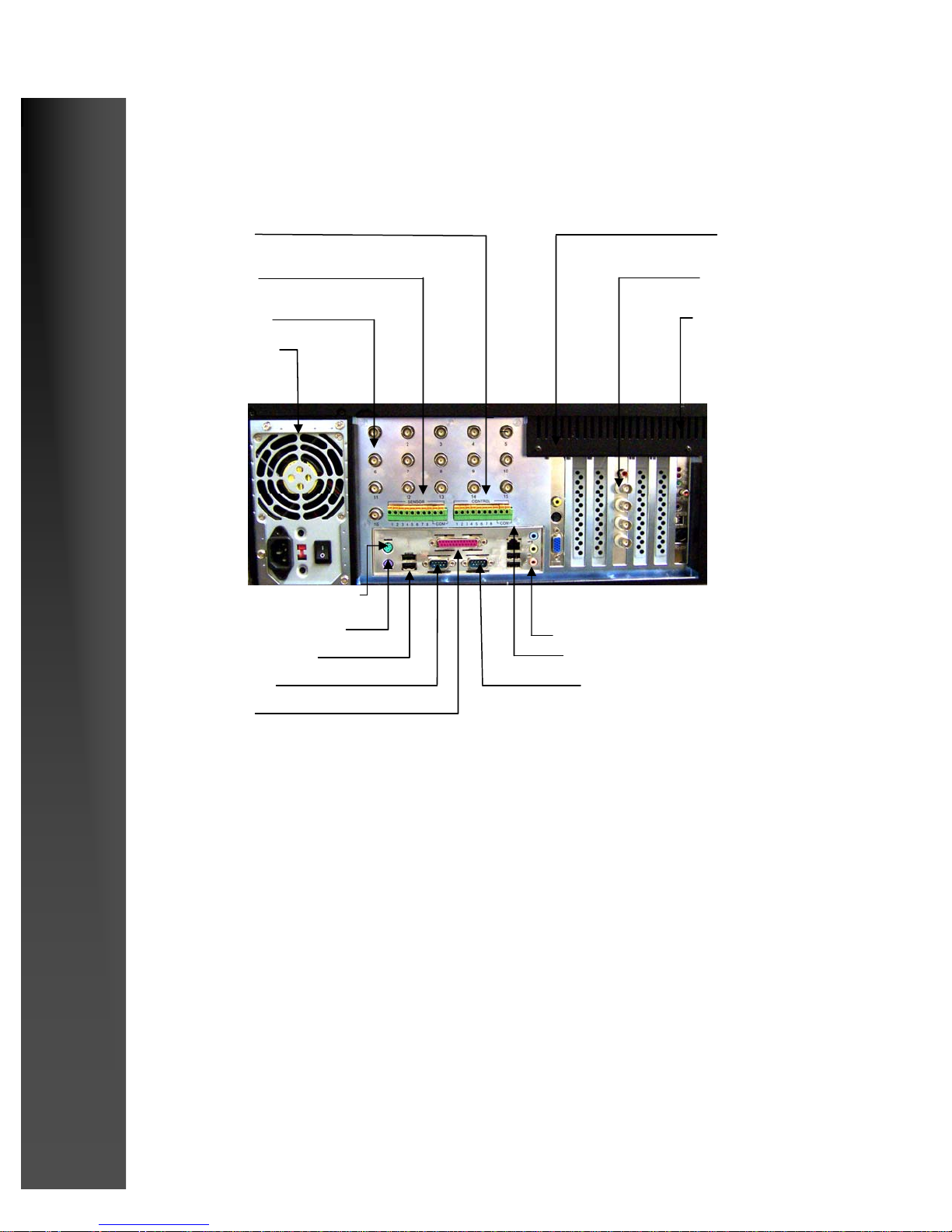
1.2) Rear View ______________________________________________________ 7
1.3) Connecting Pan/Tilt Drive _________________________________________ 8
1.4) Connecting PSTN, ISDN, or leased circuit______________________________ 9
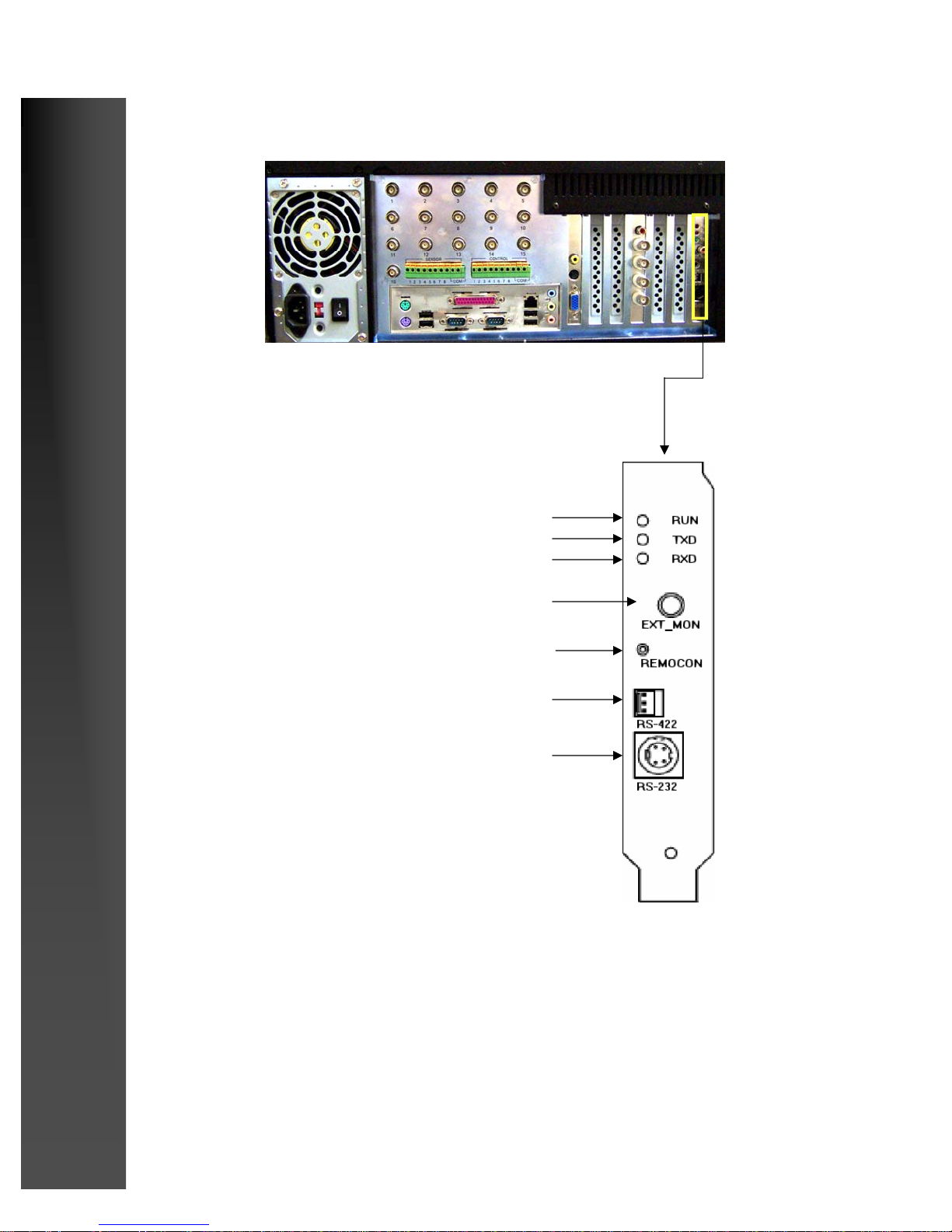
1.5) External Center Connection _______________________________________ 10
1.6) External Control Connection ______________________________________ 10
System Setup
1.7) Main Screen ___________________________________________________ 12
1.8) Setup _________________________________________________________ 14
1.9) Hardware Setup-Cameras _________________________________________ 15
1.10) Hardware Setup-Sensors__________________________________________ 17
1.11) Hardware Setup-Controls _________________________________________ 18
1.12) Hardware Setup-External Monitor __________________________________ 19
1.13) Motion Detection _______________________________________________ 20
1.14) Recording/Display ______________________________________________ 23
1.15) Schedule Setup _________________________________________________ 25
1.16) Schedule Setup-Holiday __________________________________________ 28
1.17) Screen Division_________________________________________________ 29
1.18) Modem _______________________________________________________ 30
1.19) Site Information ________________________________________________ 33
1.20) View Log _____________________________________________________ 37
1.21) Password Setup_________________________________________________ 38
1.22) Audio Setup ___________________________________________________ 39
1.23) Microphone and Speaker Setup ____________________________________ 40
1.24) Audio (advanced options)_________________________________________ 42
1.25) System Setup___________________________________________________ 43
1.26) Adding Backup Schedule _________________________________________45
1.27) Backup Media-local drive_________________________________________ 46
1.29) Easy Update ___________________________________________________ 49
1.30) Email Transmission _____________________________________________ 53
1.31) Motion Tracking ________________________________________________ 54
1.32) Storage Setup __________________________________________________ 57
1.33) E-Map ________________________________________________________ 58

4
T
TABLE
ABLE
OF
OF C
CONTENTS
ONTENTS
Chapter 2: Operation
2.1) Pan/Tilt Control for P/T/Z cameras__________________________________ 59
2.2) Pan/Tilt Zoom Controls __________________________________________ 61
2.3) Live Audio ____________________________________________________ 62
Search Mode
2.4) Entering into Search Mode _________________________________________ 63
2.5) Search Mode: Still Image Tools ________________________________ 64
2.6) Search Mode: Search Tools____________________________________ 65
2.7) Search Mode: Playback Controls________________________________ 66
2.8) Search Modes_______________________________________________ 67
2.9) Search Mode: Skip/Delay _____________________________________ 78
2.10) Search Mode: Index Search____________________________________ 79
2.11) Search Mode: Search Option Panel ______________________________ 79
2.12) Search Mode: Object Search ___________________________________ 70
2.13) Search Mode: Audio Playback__________________________________ 73
2.14) Search Mode: Installing a Local Printer __________________________ 74
2.15) Search Mode: Installing a Network Computer______________________ 76
2.16) Backup _______________________________________________________ 77
2.17) Floppy Backup______________________________________________ 78
2.18) Watermark Checker__________________________________________ 79
2.19) Time Backup _______________________________________________ 80
2.20) AVI Backup________________________________________________ 81
2.21) Email Backup_______________________________________________ 82
2.22) Common Backup Options _____________________________________84
2.23) Search Mode/Backup Select Media _________________________________ 85
2.24) CD Backup ____________________________________________________ 88

5
C
CHAPTER
HAPTER 1:
1:
I
INSTALLATION
NSTALLATION
AND
AND S
SETUP
ETUP
I
INSTALLATION
NSTALLATION...
...

6
Digital Recording Systems
Follow the steps below to install the DVR:
>
-Place the DVR to proper place following safety precautions on page 2.
>
-Connect cameras to the DVR (see
1.3 if PAN/TILT cameras are used)
>
-Connect the DVR to communication network (see 1.4)
>
-Connect external sensors and controls (see 1.5 and 1.6)
>
-Plug in the watchdog cable
>
-Plug in the power cable
IMPORTANT: unconnected watchdog cable is common mistake when installing
DVR and causes rebooting every 10 minutes that may damage the hard disk in
the DVR
1.1 Installation Procedure

7
Digital Recording Systems
1.2 Rear View
Power Supply
Camera Inputs
Sensors
Controls
K10 1616
KMC 4400
AGP Card
Sound
Com2
Printer Port
COM 1
USB
Mouse
Keyboard
Network Port

8
Digital Recording Systems
1.3 Connecting PAN/TILT drive
RUN LEAD
TXD LEAD
RXD LEAD
EXTERNAL MONITER
REMOTE CONTROLLER RECIEVER
RS-422 CONNECTION
(FROM RX-RECIEVER)
RS-232 CONNECTION
(FROM COM1 PORT)

9
Digital Recording Systems
PSTN
CONNECTION TO COM 2
(9 PIN)
ISDN
LINE
1.4 Connecting PSTN, ISDN, or leased circuit
A/C ADAPTER
D.S.U.
A/C ADAPTER
D.S.U.
A/C ADAPTER
A/C ADAPTER
LEASED
CIRCUIT
COM 2
RS-232 (25PIN) RS-232 (25PIN)

10
Digital Recording Systems
1.5 External sensor connection
1.6 External control connection
ALARM,SIREN, RELAY ETC.
POWER (DC 12V)
+
_

11
C
CHAPTER
HAPTER 1:
1:
I
INSTALLATION
NSTALLATION
AND
AND S
SETUP
ETUP
SETUP...
SETUP...

12
Digital Recording Systems
1.7 Main Screen
4
5
3
2
1
6
Main View Screen
This is where the live im-
ages from your cameras
will appear.
Left click on any image to
bring it to full screen
view. Left click on the
image again to return to
normal view.
Full Screen View
This button will set the main screen to “Camera
only” view. The GUI (Graphic User Interface)
which includes the Screen Division buttons, the
Event Indicators, the Clock, Setup and Search
buttons, Power button, etc. will be hidden.
Right click on the screen to return to normal
view.
Clock
Indicates current date and time
Quad Rotation Mode
Sets main view to 4 camera split and rotates view
continuously through all active cameras starting
with 1~4, then 5~8, then 9~12, then 13~16, then
back to 1~4, etc.
Click on an image, or select a Screen division
button to stop rotation and return to normal mode.
Setup and Search Modes
Left click to enter Setup (Camera selection,
Screen division, Schedule, Audio, Motion, etc.)
or Search Mode. (Review and backup recorded
data)
Storage Indicator
Top line shows total Hard Drive space allo-
cated and available for data storage.
Numbers in the blue box show Hard Drive
space that has been used for data storage in
Megabytes and Percentage of free space re-
maining. When percentage of free space
reaches 0%, the DVR has used all available
storage and will begin to overwrite (replace)
the oldest recorded data.
(It is normal for the ‘Free Space’ indicator to
read ‘0% Free’ once the DVR has started
overwriting the oldest data. This number will
not change unless you reallocate (erase) the
storage drive.)
1
3
4
5
6
Mode Indicator
Mode indicator will indicate whether you are in
Display, Search, or Pan /Tilt mode.
2

13
Digital Recording Systems
8 7
Power Button
Left click on the power button in Display
mode to turn off the DVR.
Unit will stop recording and turn itself off.
Use the Power switch (on the front of the
DVR) to restart the unit.
7
Camera, Sensor, and Control
-
Relay Event Indicators
Each numbered button corresponds to the simi-
larly numbered device in each category. Camera
indicators will flash when a camera detects mo-
tion. Sensor indicators will flash when a device
(Glass break or motion detector) is tripped.
Control indicators will flash when a relay
(Alarm, siren, strobe, etc.) has been activated.
Control relays may also be manually activated
by left clicking on the indicator. Click on it
again to deactivate.
8
Screen Division Selections
Select the number of cameras you wish to view
on the main screen.
Choose 4, 6, 9, 10, 13, or 16 camera splits
The cameras that will appear in each view are
assignable in setup under “Screen Division”
9
9
10
Left click on any image to bring it to full
screen view. Left click on image again to bring
it to normal view.
10

14
Digital Recording Systems
Left click on the “Setup” button to enter Setup mode.
>When you click on setup for the first time you
will be prompted to enter a password.
Leave the user level set to Level 1 (Administrator) and
use the keyboard to enter a 4 digit numeric password (4
characters, all numbers). You may left click on the num-
bers on the ‘Virtual Keypad’ if no keyboard is available.
You may also press “Enter” on your keyboard or click on
“OK” with the left mouse button if you want no password
set up at this time. (You can change this later in the
“Password Setup” section.)
>You will then be asked if you want to create the
default user database.
Click on “Yes” or press “Enter” on your keyboard to continue.
>You will then be prompted to “Confirm” or, re-enter your pass-
word again to gain entry to Setup mode.
>Your new DVR is “Ready to Go” right
out of the box. It is factory preset to start up
and begin recording data without any effort
on your part. Just hook up your cameras and
turn it on.
>In order to fine tune your installation
and customize the DVR to get the best per-
formance for your particular situation, or to
setup extra features such as Pan/Tilt/Zoom
cameras, Sensors and Control relays, Record
mode quality and scheduling, Custom screen
divisions, etc., the DVR is equipped with an
extensive array of options available through
the “Setup” mode.
1.8 Setup
Remember your password!
Once you have created the password database you will not be able to
access Setup or Search mode without it.

15
Digital Recording Systems
[Sensor]
You can connect sensors to available cameras.
This functions enables cameras to record auto-
matically when the connected sensor (s) is trig-
gered.
To connect a sensor to a camera, type the num-
ber of the sensor in appropriate camera number.
If you wish to connect to multiple sensors to a
camera, type sensor numbers in the box, sepa-
rating them by comma.
Example, in order for Camera 3 to start re-
cording when Sensor 1 or Sensor 3 is triggered,
type “I, 3” in [sensor] box against Camera 4.
[Setup]
Check the box to use the camera.
[Motion]
You can link cameras to other available
cameras. This function enables linked
cameras to record automatically when the
main camera detects movement.
To link a camera to another camera, type the
number of the camera you wish to connect in
appropriate camera number. If you wish to
connect multiple cameras to a camera, type
camera numbers in the box, separating them
by comma.
Example: In order for Camera 5 to start re-
cording when Camera 1 or Camera 2 detects
motion, type “1,2”
in [Motion] box against
Camera 5
1
3
[Name]
Type in the camera names. Up to 14 characters
are allowed.
2
Number of sensors supported ;
-4 sensors : DN1808S, 4408S, 44208S
-8 sensors : All of the rest models.
-16 sensors: available as an option
for any 16- channel model.
4
3 42
1
1.9) Hardware Setup - Cameras
Hardware setup allows
users to modify external
devices configurations,
such as cameras, sen-
sors, and controls.

16
Emergency
Select a preset location where Pan/Tilt camera will
return to when any linked sensor is triggered.
[Type]
Use the scroll bar to select PAN/TILT camera model from the list.
This option box is disabled if [P/T] box is not selected.
Digital Recording Systems
[P/T]
Check the box if the camera is on PAN/Tilt type.
5
6 75
6
7

17
[Setup]
Check the box to enable sensors. Un-
check the box to disable sensors. Sensor inputs
are standard on Rack Mount units and optional
on Desktop units. If your unit does not have
sensor inputs then do not use this function.
[Recording Time]
Select the number of seconds to record
when a sensor is triggered. This function
will not work if the recording schedule is
not set to
Sensor
or
Motion
Digital Recording Systems
[Use alarm]
Selecting [
Use alarm
] will enable the built-in
internal speaker to beep if a sensor is triggered.
The speaker however will not beep if the corre-
sponding camera schedule is set to
Continuous
Recording
.
[NC/NO]
Choose sensor type. Click the button to
switch between
[NC]
and
[NO]
sensor
types
.
>
NC
= Normally Close type. If the door/
object with the sensor installed is not
closed, the sensor will trigger.
>
NO
= Normally Open type. If the door ob-
ject with
the sensor installed is not open, the
sensor will trigger
2
3
3
4
2
1
1.10 Hardware Setup - Sensors
4
1

18
[Setup]
Check the box to use the controls.
[Working sec]
Assign how long the control will stay ac-
tive once it is triggered. Maximum is 255
seconds and default is 0 seconds
Digital Recording Systems
[Sensor]
To connect a sensor to a control, type the
number of the sensor on appropriate control
number.
If you wish to connect multiple sensors to a con-
trol, type
the sensor numbers in the box, separat-
ing them by commas.
Example: In order to turn on Control 3 when
Sensor 1 or Sensor 2 triggers, type “1,2”
in the
box against Control 3.
1
[Name]
Type in control names. Up to 14 characters are
allowed
.
2
3
3 4
2
1
1.11 Hardware Setup - Controls
[Auto On/Off]
Auto function automatically activates controls
during selected time. To enable Auto function
choose the time from scroll list. Default is set
from 00:00 to 24:00.
4
5
5

19
[Setup time (sec)]
Select time for displaying a channel on the external monitor.
Digital Recording Systems
1
[Camera]
Select the channel you wish to display on the external monitor.
2
2
1
1.12 Hardware Setup - External Monitor
Home TV or normal
analog monitor can
be
used as an external
monitor to view images
from DVR.
[Tip]
Images from external monitor output use Split Screening Method instead of Consecutive Conversion
Method when using models DN-3416 and DN-34216. It might not indicate set item for external monitor.
In case of DN6816 and DN68232, the screen on the external monitor is the same as seen on the DVR.
The external monitor out is not available with DN34XX, DN35XX and DN68XX.
Launch Microsoft Office Outlook.lnk

20
[Camera]
Select the camera you wish to setup. The de-
scription below is related to the camera you
selected here
.
[Control]
When the camera detects motion, the connected
control will activate for the designated time.
Digital Recording Systems
[Alarm]
If the box is checked, the internal speaker will
beep when the camera detects motion
.
The speaker however will not beep if the camera
is set to Continuous Recording mode in Sched-
uled Setup (see page 26). The speaker’s activa-
tion time can set by the scroll lists
.
1
[Detection Area]
To enable cameras to record automatically by
motion detection, you mush select the detection
areas. To select detection area, place the mouse
cursor over the channel screen and drag the
cursor in any direction you wish. You can as-
sign up to 5 separate areas for each camera
.
2
31
1.13 Motion Detection
3 [Sensitivity]
Change sensitivity of motion detection. Default
value is set to 15 and it is the recommended
value.
4
5
4
5
2
This manual suits for next models
16
Table of contents
Other CCTV DVR manuals