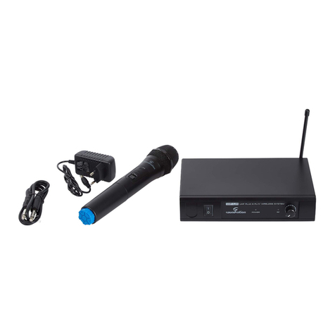
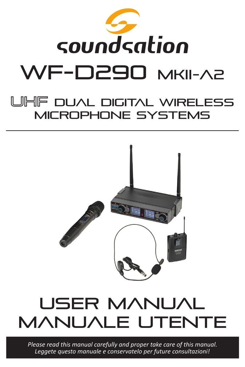
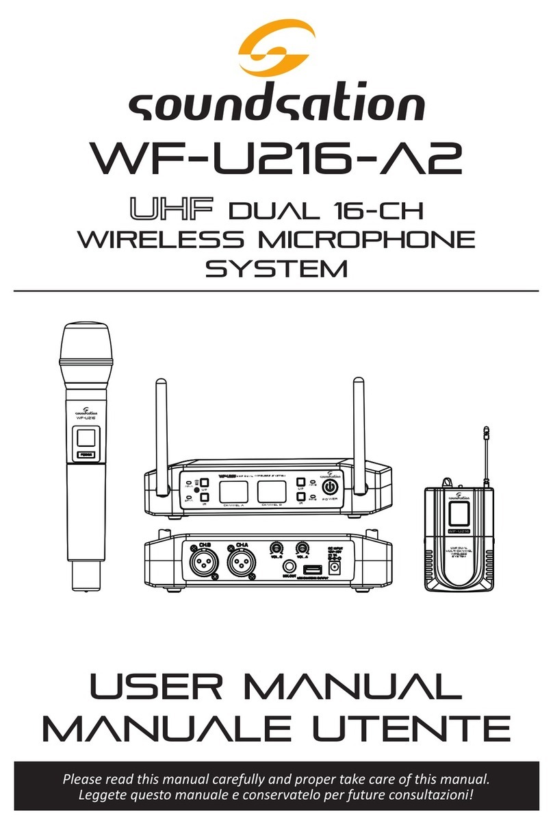
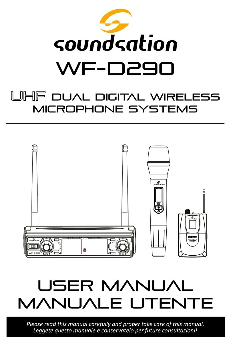
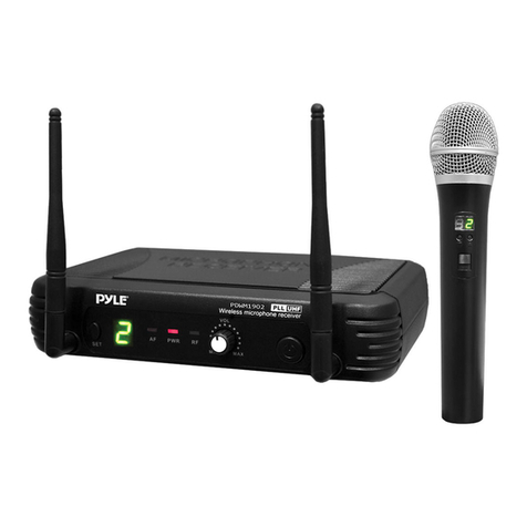
Sound Sation WF-U24 User manual

Please read this manual carefully and proper take care of this manual.
USER MANUAL
WF-U24
4-channel dual
WIRELESS MICROPHONE
SYSTEMS
Leggete questo manuale e conservatelo per future consultazioni!
MANUALE utente

Dear customer,
First of all thanks for purchasing a SOUNDSATION® product. Our mission is to satisfy
all possible needs of musical instrument, professional audio and lighting users offering
a wide range of products using the latest technologies.
We hope you will be satised with this item and, if you want to collaborate, we are
looking for a feedback from you about the operation of the product and possible im-
provements to introduce in the next future. Go to our website www.soundsationmusic.
com and send an e-mail with your opinion, this will help us to build instruments ever
closer to customer’s real requirements.
One last thing: read this manual before using the instrument, an incorrect operation
can cause damages to you and to the unit. Take care!
The SOUNDSATION Team
Gentile Cliente,
Grazie per aver scelto un prodotto SOUNDSATION®. La nostra missione è quella di
offrire ai nostri utenti una vasta gamma di strumenti musicali ed apparecchiature audio
e lighting con tecnologie di ultima generazione.
Speriamo di aver soddisfatto le vostre aspettative e, se voleste collaborare, saremmo
lieti di ricevere un vostro feedback sulla qualità del prodotto al ne di migliorare co-
stantemente la nostra produzione. Visitate il nostro sito www.soundsationmusic.com ed
inviateci una mail con la vostra opinione, questo ci aiuterà a sviluppare nuovi prodotti
quanto più vicini alle vostre esigenze.
Un’ultima cosa, leggete il presente manuale al ne di evitare danni alla persona ed al
prodotto, derivanti da un utilizzo non corretto.
Il Team SOUNDSATION

3
ENGLISH
TABLE OF CONTENTS
1. UNBOXING.................................................................................................................6
2. ACCESSORIES .............................................................................................................6
3. OVERVIEW..................................................................................................................6
4. FEATURES ...................................................................................................................7
5. WF-U24 RECEIVER .....................................................................................................7
5.1. Receiver Operation................................................................................................................................................9
6. HANDHELD MIC (WF-U24HH and WF-U24HP models)......................................10
7. POCKET TRANSMITTER (WF-U24HP / WF-U24PP) ........................................................ 11
8. HANDHOLD MICROPHONE USE............................................................................12
9. AUDIO CONNECTION..............................................................................................13
10. WF-RACK KIT1 & KIT2 ............................................................................................14
10.1. WF-RACK KIT1.......................................................................................................................................................14
10.2. WF-RACK KIT2.......................................................................................................................................................16
11. SPECIFICATIONS ......................................................................................................19
12. WARRANTY AND SERVICE .....................................................................................20
13. 14. WARNING ..........................................................................................................20

4
ENGLISH
wf-u24 User manual
IMPORTANT SAFETY SYMBOLS
The symbol is used to indicate that some hazardous live terminals are
involved within this apparatus, even under the normal operating con-
ditions, which may be sufcient to constitute the risk of electric shock
or death.
The symbol is used in the service documentation to indicate that spe-
cic component shall be replaced only by the component specied in
that documentation for safety reasons.
Protective grounding terminal
Alternating current/voltage
Hazardous live terminal
Denotes the apparatus is turned on
Denotes the apparatus is turned off
WARNING: Describes precautions that should be observed to prevent the danger
of injury or death to the operator.
CAUTION: Describes precautions that should be observed to prevent danger of
the apparatus.
TAKING CARE OF YOUR PRODUCT
fRead these instructions
fKeep these instructions
fHeed all warning
fFollow all instructions
Water / Moisture
The apparatus should be protected from moisture and rain and can not be used near
water; for example near a bathtub, a kitchen sink, a swimming pool, etc.
Heat
The apparatus should be located away from heat sources such as radiators, stoves or
other appliances that produce heat.

5
ENGLISH
wf-u24 User manual
Ventilation
Do not block areas of ventilation opening. Failure to do could result in re. Always
install according to the manufacturer's instructions.
Object and Liquid Entry
Objects do not fall into and liquids are not spilled into the inside of the unit for safety.
Power Cord and Plug
Protect the power cord from being walked on or pinched particularly at plugs, conve-
nience receptacles, and the point where they exit from the apparatus. Do not defeat
the safety purpose of the polarized or grounding-type plug. A polarized plug has two
poles; a grounding-type plug has two poles and a third grounding terminal. The third
prong is provided for your safety. If the provided plug does not t into your outlet, refer
to an electrician for replacement.
Power Supply
In case of external power supply, the apparatus should be connected to the power sup-
ply only of the type as marked on the apparatus or described in the manual. Failure to
do could result in damage to the product and possibly the user. Unplug this apparatus
during lightning storms or when unused for long periods of time.
Fuse
To prevent the risk of re and damaging the unit, please use only of the recommend-
ed fuse type as described in the manual. Before replacing the fuse, make sure the unit
turned off and disconnected from the AC outlet.
Electrical Connection
Improper electrical wiring may invalidate the product warranty.
Cleaning
Clean only with a dry cloth. Do not use any solvents such as benzene or alcohol.
Servicing
Do not implement any servicing other than those means described in the manual. Refer
all servicing to qualied service personnel only. Only use accessories/attachments or
parts recommended by the manufacturer.
Warning
Please remember the high sound pressure do not only temporarily damage your sense
of hearing, but can also cause permanent damage. Be careful to select a suitable vol-
ume.
Interference from cell phone
Using a cell phone near the wireless system can induce noise. If this occurs, move the
cell phone further away from the components of the wireless system.

6
ENGLISH
wf-u24 User manual
1. UNBOXING
Inside package you’ll nd following items:
WF-U24HH WF-U24HP WF-U24PP
1x Receiver 1x Receiver 1x Receiver
2x Handheld Transmitter 1x Handheld Transmitter /
/ 1x Pocket Transmitter 2x Pocket Transmitter
/ 1x Headset Microphone 2x Headset Microphone
4x Type AA 1.5V Batteries 4x Type AA 1.5V Batteries 4x Type AA 1.5V Batteries
This User Manual This User Manual This User Manual
ATTENTION: Packaging bag is not a toy! Keep out of reach of children!!! Keep
in a safe place the original packaging material for future use.
2. ACCESSORIES
SOUNDSATION can supply a wide range of quality accessories that you can use with
your WIREFREE Series wireless microphone system, like Cables, Mixers, Speakers, Ampli-
ers, Stands, etc. All products in our catalogue has been long tested with this device so
we recommend to use Genuine SOUNDSATION Accessories and Spare Parts. Ask your
SOUNDSATION dealer for any accessories you could need to ensure best performance
of the product.
3. OVERVIEW
This wireless microphone series adopts the fully integrated solution single chip, inte-
grated microphone amplier, audio based on DSP processor, PLL frequency synthesizer,
etc. This allows us to offer highly professional performance yet cost-effective products
to everyone.
SOUNDSATION WF-U24 wireless systems are available in three different congurations:
WF-U24HH
• 1x Dual 4-Channel UHF Receiver
• 2x 4-Ch UHF Handheld Transmitters with Professional Dynamic Cardioid Capsule
WF-U24HP
• 1x Dual 4-Channel UHF Receiver
• 1x 4-Ch UHF Handheld Transmitter with Professional Dynamic Cardioid Capsule
• 1x 4-Channel UHF Pocket Transmitter
• 1x Headset Microphone with Professional Condenser Cardioid Capsule
WF-U24PP
• 1x Dual 4-Ch UHF Receiver

7
ENGLISH
wf-u24 User manual
• 2x 4-Ch UHF Pocket Transmitter
• 2x Headset Microphone with Professional Condenser Cardioid Capsule
4. FEATURES
fSMT technology with surface mounting components
fDesigned for professional live and educational purposes
fUnidirectional cardioid dynamic microphone, clear and bright sound
fSpecial compression/expansion circuitry to greatly improve S/N ratio without affect-
ing audio quality
fHigh efciency batteries consumption design, in order to guarantee the use of the
wireless microphone even after many hours
fMultiple noise control circuit, refuse to external interferences and the opening s/q
system
5. WF-U24 RECEIVER
WF-U24 receiver has many connections, controls and indicators whose use it is import-
ant to know.
1. POWER:
This button switches the unit ON and OFF

8
ENGLISH
wf-u24 User manual
2. VOLUME-A:
It adjusts audio level in A balanced output (11).
3. RF-A:
When lit, this LED indicates the receiving on Channel-A. If RF-A is off, it means that
there is no signal from the transmitter; if ashing, it indicates that there are interfer-
ences or RF signal is low. In these cases we recommend using one of the other four
available frequencies.
4. POWER LED:
Indicates that the receiver is ON.
5. RF-B:
When lit, this LED indicates the receiving on Channel-B. If RF-B is off, it means that there
is no signal from the transmitter; if ashing, it indicates that there are interferences or
RF signal is low. In these cases we recommend using one of the other four available
frequencies.
6. VOLUME-B:
Adjusts audio level in B balanced output (10).
7. ANT-A:
Receives A-Channel radio signal.
NOTE: For proper operation, the antennas must be angled 45° towards the
outside. Never cover the antennas during use.
8. ANT-B:
Receives B-Channel radio signal.
9. MIX OUT:
This line-level unbalanced output with ¼” jack contains both A and B audio signals,
each with level adjusted according to VOLUME A and B knobs at points (2) and (6).
10. BALANCED OUT B:
It is the B-channel line-level balanced output with XLR connector, whose level is adjust-
ed by VOLUME B knob (6).
11. BALANCED OUT A:
It is the A-channel line-level balanced output with XLR connector, whose level is adjust-
ed by VOLUME A knob (2).
12. CHANNEL B:
It selects B-channel operating frequency. There are 4 different frequencies and can be
selected by moving the four switches according to following code:

9
ENGLISH
wf-u24 User manual
Channel CH1 CH2 CH3 CH4
Frequency 863.000 MHz 863.500 MHz 864.000 MHz 865.000 MHz
13. CHANNEL A:
It selects A-channel operating frequency. Even for A-channel there are 4 frequencies
available. Refer to the instructions provided at previous point.
14. DC INPUT:
It connects the unit to the supplied 17Vdc – 300mA power supply.
5.1. Receiver Operation
POWER CONNECTION:
Plug the supplied adapter into a 230-240V outlet and power cord to the DC INPUT
connector (14).
AUDIO OUTPUT CONNECTION:
You can use the two balanced outputs (10) / (11) if you want to separate the two audio
signals, or you can use the unbalanced mix output (9) if you don’t have a mixer, and
want to use the internal mixer.
POWER ON:
Press POWER on/off (1). POWER Indicator (4) will light, it means receiver is under nor-
mal working status.
WARNING: Please turn down volume control knobs (2) and (6) to minimum
before turning power on, and adjust volume after the receiver is working
properly.

10
ENGLISH
wf-u24 User manual
6. HANDHELD MIC (WF-U24HH and WF-U24HP models)
1. GRILL:
Protects microphone capsule. Do not remove this
cap to prevent damage to internal components.
2. LED:
This LED lights up briey when you turn on the mi-
crophone. Under normal operating conditions - with
switch (2) in standby or ON position and batteries in
normal conditions, this LED does not light. It ashes
when batteries charge level is low and must be
replaced.
3. ON/OFF SWITCH:
It has 3 positions: when it’s all down, transmitter is
off. When it is in central position, the transmitter is
on but audio is disabled; nally, when it’s all up, the
transmitter is working and the audio is active.
NOTE: Standby central position allows the unit to transmitter without audio.
This option is important to prevent interference in the receiver due to the
absence of a radio transmitting signal. It is, therefore, suggested to ALWAYS
use this standby position when you temporarily don’t sing or play but wire-
less microphone is connected to an audio system (e.g. during a pause in a
show). You can move the switch to OFF position (all down) only when you are
sure that the sound system volume is low.
4 BATTERY SLOT:
Batteries are housed inside the transmitter. Use 2x 1.5V AA type batteries paying atten-
tion to their polarity.
5 BATTERY COVER:
For battery replacement follow the instructions below:
fApply a slight pressure at the top of the door (5) and pull down. Remove the cover.
fInsert or replace the batteries in the compartment, observing the +/- polarity marked
on the bottom.
fReplace the cover on the bottom of the battery slot.
fPush up the cover of the microphone in order to completely close it.
6 DIP-SWITCH:
This multi-switch allows you to choose one of the four available operating frequencies.
In order to work properly, please correspond with the channels combinations of receiv-
er (12) & (13).

11
ENGLISH
wf-u24 User manual
7. POCKET TRANSMITTER (WF-U24HP / WF-U24PP)
1. MICROPHONE:
In WF-U24HP and WF-U24PP models there are, re-
spectively, 1 and 2 headset microphones with cardioid
condenser capsule. Connect mini-jack connector into
socket (2).
2. INPUT SOCKET:
Connect the microphone or audio source connector
here.
3. POWER INDICATOR:
This LED lights up briey when you turn on pocket
transmitter. Under normal operating conditions, this
LED does not light. It ashes when batteries charge
level is low and must be replaced.
4. POWER SWITCH:
It switches on and off the pocket transmitter
5. VOLUME ADJUST:
It adjusts sound source input level and allows you to adapt transmitter gain to any type
of audio source.
6. ANTENNA:
It allows radio signal transmission. Be careful to not bend or break this terminal.
7. DIP SWITCH:
This multi-switch allows you to choose one of the four available operating frequencies.
In order to properly work, please correspond with the channels combinations of receiv-
er (12) & (13).
8. BATTERY SLOT:
Batteries are housed inside the transmitter. Use 2x 1.5V AA type batteries, paying atten-
tion to their polarity.
9. BATTERY COVER:
For battery replacement follow the instructions below:
fApply a slight pressure at the top of the two sides of this door (9) and open the slot.
fInsert or replace the batteries in the compartment, observing the +/- polarity marked
on the bottom.
fClose the cover so as to avoid the leakage of the batteries.

12
ENGLISH
wf-u24 User manual
8. HANDHOLD MICROPHONE USE
fDon’t hold microphone grill.
fAvoid holding the microphone on antenna position.
fDon’t put two microphones in contact.
ATTENTION: Operating distance between microphone grill and mouth must
be less than 15cm.
fDo not point the microphone toward a loudspeaker to avoid Larsen effect, which
could damage your audio system.

13
ENGLISH
wf-u24 User manual
9. AUDIO CONNECTION
You need XLR balanced cables for connections from the system. See the pictures below
that show the internal wiring of these cables. Be sure to use only high quality cables
(visit our website www.soundsationmusic.com for further details).
Balanced use of XLR connectors
1= Ground/Shield
2= Hot (+)
3= Cold (-)
INPUT OUTPUT
In case of unbalanced use Pins 1 and 3 will be jumped
Balanced use of 1/4” jack TRS connector
Strain relief
clamp
Sleeve
Tip
Sleeve
Ground shield
Ring Ring
Cold (- Ve)
Tip
Hot (+ Ve)
You can, of course, connect unbalanced equipment to balanced outputs too. Use either
mono and stereo jack, making sure ring and collar are connected together (or pins 1 &
3 in the case of XLR connectors).
Unbalanced use of 1/4” jack TS connector
Strain relief
clamp
Sleeve
Tip
Sleeve
Ground shield
Tip
Signal

14
ENGLISH
wf-u24 User manual
10. WF-RACK KIT1 & KIT2
WF-U24 series receiver units can be mounted in 19” standard rack units using option-
al kits (contact your dealer or go to www.soundsationmusic.com for more details) to
adapt the receiver to any 19” rack. 2 different kits are available:
fWF-RACK KIT1: To set one SOUNDSATION WIREFREE series receiver in one 19” rack
unit.
fWF-RACK KIT2: To set two SOUNDSATION WIREFREE series receivers in two 19” rack
units.
NOTE: WF-RACK KIT2 is designed for use with different SOUNDSATION
wireless systems models. Normally, in the case of receivers with removable
antennas, this kit allows the installation of two receivers in two 19” rack units
(refer to previous image). In the specic case of WF-U24, however, since the
antennas are not removable, the two receivers can t only one 19” rack unit
with antennas folded in order to avoid them to touch each other and be as
much distant as possible.
10.1. WF-RACK KIT1
The kit includes:
A. 2x ¼ rack unit adapter
B. 2x Extension cables for Antenna

15
ENGLISH
wf-u24 User manual
C. 4x Screws to fasten the receiver to the two rack adapters
NOTE: The kit doesn’t include screws to fasten the whole block (receiver and
adapters) to the 19” rack chassis.
WF-RACK KIT1 assembling
1. Remove the two plastic parts on two sides of the receiver.
2. Place the A adapter so that the two lateral holes match those on the receiver side.
3. Fasten the adapter using two screws as shown in the following picture.
4. Repeat steps 1 to 3 of this section on the other side of the receiver.
5. This hole is normally used to attach the extension cables supplied with the kit in
order to place the antennas of the receiver outside the rack. In the specic case of
WF-U24, however, these extensions and this hole are not used because the rear
antennas are not removable.
1210mm
3
5
2
4
ATTENTION: Note that the antennas should be kept in a horizontal or vertical
position but with an angle of about 45° to one another as much as possible.
The maximum distance from the bottom of the receiver to the top of the
antenna in vertical position is 210mm; the maximum horizontal distance is
maximum 300mm.

16
ENGLISH
wf-u24 User manual
300 mm ca.
10.2. WF-RACK KIT2
The kit includes:
A
B C D
A. 1x 19” rack panel
B. 2x Lateral brackets
C. 4x Receiver’s coupling brackets
D. 4x Extension cables for Antenna
E. 12x Screws to fasten the two receiver each other and then to the rack adapters
NOTE: The kit doesn’t include screws to fasten the whole block (receiver and
adapters) to the 19” rack chassis.

17
ENGLISH
wf-u24 User manual
WF-RACK KIT2 assembling
1
2
3
3
210mm
1. Remove the 4 plastic parts on two sides of the receivers.
2. Place the two receivers so that the holes on the upper and lower part coincide as
shown in previous picture and attach one coupling bracket on the top and one on
the bottom of the receivers using the supplied screws.
3. Place the lateral brackets respectively on the left and right side of the two connect-
ed receivers using the supplied screws.
The 19” rack unit panel A and the 4 holes are normally used for attach the extension ca-
bles D supplied with the kit to place the antennas of the two receivers outside the rack.
In the specic case of two WF-U24, however, both plate and extensions are not used as
the rear antennas are not removable.
ATTENTION: Note that the antennas should be kept in a horizontal or vertical
position but with an angle of about 45° to one another as much as possible.
The maximum distance from the bottom of the receiver to the top of the
antenna in vertical position is 210mm; the maximum horizontal distance is
maximum 300mm.

18
ENGLISH
wf-u24 User manual
300 mm ca.

19
ENGLISH
wf-u24 User manual
11. SPECIFICATIONS
SYSTEM
Carrier Frequency: UHF 863-865MHz
Frequencies: 863.000 / 863.500 / 864.000 / 865.000 MHz
Frequency Stabilization: Automatic calibration
Dynamic Range: > 90dB
Total Harmonic Distortion: < 0.4%
Frequency Response: 40Hz-15KHz ±3dB
Packing Dimension (WxHxD): 375 x 285 x 65 mm
Packing Gross Weight: 1.6kg (U24HH), 1.5kg (U24HP), 1.3kg (U24PP)
RECEIVER
Power Supply: DC17V - 300mA
Consume Power: < 4W
Signal/Noise Ratio: > 95dB
Receiving Sensitivity: >7dBuV (SINAD=30dB)
De-Emphasis: 75uS
Dimension (WxHxD): 210 x 48 x 133 mm
Antenna: 190 x Ø13 mm
Net Weight: 0.39kg
HANDHELD MICROPHONE / POCKET TRANSMITTER
Transmitter Power: 10mW
Modulation Type: FM
Max Deviation: ±20KHz
Battery Voltage: 3V (2x1.5V AA Battery)
Continuum Using: 5 hours
Handheld Microphone Dimension
(W/DxH):
Ø53 x 255 mm
Handheld Microphone Net Weight: 0.26kg (batteries included)
Pocket Transmitter Dimension
(WxHxP):
62 x 103 x 30 mm
Antenna (W/DxH): Ø3 x 9 mm
Pocket Transmitter Net Weight: 0.135kg

20
ENGLISH
wf-u24 User manual
12. WARRANTY AND SERVICE
All SOUNDSATION products feature a limited two-year warranty. This two-year warranty is specic
to the date of purchase as shown on your purchase receipt.
The following cases/components are not covered from the above warranty:
• Any accessories supplied with the product
• Improper use
• Fault due to wear and tear
• Any modication of the product effected by the user or a third party
SOUNDSATION shall satisfy the warranty obligations by remedying any material or manufacturing
faults free of charge at SOUNDSATION’s discretion either by repair or by exchanging individual
parts or the entire appliance. Any defective parts removed from a product during the course of a
warranty claim shall become the property of SOUNDSATION.
While under warranty period, defective products may be returned to your local SOUNDSATION
dealer together with original proof of purchase. To avoid any damages in transit, please use the
original packaging if available. Alternatively you can send the product to SOUNDSATION SERVICE
CENTER – Via Enzo Ferrari , 10 – 62017 Porto Recanati - Italy . In order to send a product to service
center you need an RMA number. Shipping charges have to be covered by the owner of the prod-
uct.
For further information please visit www.soundsationmusic.com
13.14. WARNING
PLEASE READ CAREFULLY – EU and EEA (Norway, Iceland and Liechtenstein) only
This symbol indicates that this product is not to be disposed of with your household waste, ac-
cording to the WEEE Directive (2202/96/EC) and your national law.
This product should be handed over to a designated collection point, e.g., on an authorized one-
for-one basis when you buy a new similar product or to an authorized collection site for recycling
waste electrical and electronic equipment (WEEE).
Improper handling of this type of waste could have a possible negative impact on the environment
and human health due to potentially hazardous substances that are generally associated with EEE.
At the same time, your cooperation in the correct disposal of this product will contribute to the
effective usage of natural resources.
For more information about where you can drop off your waste equipment for recycling, please
contact your local city ofce, waste authority, approved WEEE scheme or your household waste
disposal service.
This manual suits for next models
3
Table of contents
Languages:
Other Sound Sation Microphone System manuals
Sound Sation
Sound Sation WF-D190 User manual

Sound Sation
Sound Sation POCKETMIC U16 User manual

Sound Sation
Sound Sation WF-U2300 Series User manual

Sound Sation
Sound Sation WF-U11 User manual

Sound Sation
Sound Sation WF-D190H MKII User manual

Sound Sation
Sound Sation DSKIT-7 User manual

Sound Sation
Sound Sation WF-D290 User manual

Sound Sation
Sound Sation WF-V11 User manual

Sound Sation
Sound Sation WF-U1300 User manual

Sound Sation
Sound Sation WF-U216 Series User manual