SOUNDLIGHT 3044BH User manual

1
OPERATING MANUAL
DMX / 1-10V Decoder 3044BH Mk1
(C)SOUNDLIGHT1996-2006 * ALLRIGHTSRESERVED * NOPARTOFTHISMANUALMAYBEREPRODUCED,
DUPLICATEDORUSEDCOMMERCIALLYWITHOUTTHEPRIORWRITTENCONSENTOFTHEOWNER * ALL
STATEMENTS WITHIN THIS MANUAL HAVE BEEN CHECKED CAREFULLY AND ARE BELIEVED TO BE
ACCURATE, HOWEVER SOUNDLIGHT DOES NOT ASSUME ANY RESPONSIBILITY FOR ERRORS OR
OMISSIONS. * THEUSERHASTOCHECKTHESUITABILITYOFTHEEQUIPMENTFORTHEINTENDEDUSE.
SOUNDLIGHTEXPRESSLYEXCLUDESANYRESPONSIBILITYFORDAMAGES-DIRECTORINDIRECT-WHICH
MAYOCCURDUETOMISUSE,UNPROPERINSTALLATION,WRONGOPERATINGCONDITIONSANDNON-
COMPLIANCE TO THE INSTRUMENT'S INSTRUCTIONS, AS WELL AS IGNORANCE OF EXISTING SAFETY
REGULATIONS.
SOUNDLIGHT The DMX Company Glashüttenstrasse 11 D-30165 Hannover Tel.: 0511-3730267

2
Thank you for choosing a SOUNDLIGHT device.
The SOUNDLIGHT DMX to 1...10V Converter 3044B-H is an intelligent DMX converter decoding
digital data complying with standard USITT DMX512 and DIN 56930-2 to analog output to drive
analog dimmable ballasts for flourescent tubes. The card can be used with all standard light control
systems. Its special advantages include:
-universal protocol decoding
Recognizes all variants of the protocol as defined by USITT / ESTA / DIN
-future-proof
The unit is software controlled an can easily be adapted to any change in protocol definition.
-high linearity
As the unit accepts and outputs data in digital format, excellent linearity chracteristics result.
-simplesupply
The power supply is achieved by its own PSU, power supply is 230V AC.
-signal loss - switchable
In the case of a loss of the drive signal the last setting will remain intact.
-fully isolated data input
Increased safety in case of system failure by optically isolated DMX data input.
-cost-effective
The SOUNDLIGHT 3004B-H is a cost-effective solution for many purposes.
APPLICATIONS
The converter 3044B-H is designed to drive flourescent light tubes with variable intensity. Up to
twenty-five electronic ballasts (assumed: max 1mA per input) may be connected per output. The unit
is well suited for all applications on stage, for TV background lighting, or for architectural lighting
purposes. The dimming range is 100% to 1%, and OFF at DMX input zero..
UNPACKING
Please unpack carefully and check that all items are intact. When leaving our factory, the card has
been in good condition. In case of damage during transport please notify the carrier immediately.
When unpacking, you should identify these items:
* the interface card 3004B-H
* this manual
The optional programming adaptor 3000P must be ordered separately.

3
CONNECTORS
The decoder 3044BH consists of these connectors:
CN2 POWER SUPPLY 230V AC
black L 230V AC LIVE 230VAC
blue N 230VAC NEUTRAL 230VAC
CN1 DMX DATA
1 grey GND, Screen -> refers to Pin 1 XLR
2 blue control signal DMX - -> refers to Pin 2 XLR
3 orange control signal DMX + -> refers to Pin 3 XLR
CN3 Adress decoder board
1 VCC (+5.0V) Logic power supply 5.0V stabilized
2 SEN Serial Enable (Strobe)
3 SCLK Serial Clock
4 SDAT Serial Data
5 LD1 LED ERROR
6 LD2 LED OK
7nc - do not use! -
8nc - do not use! -
9 GND(0.0V) Logic power supply 0.0V (GND)
10 nc - do not use! -
CN4-7 Control output to electronic ballasts ( EVG )
1 orange channel 1: control signal 1-10V output
2 white channel 1: GND 0V
3 orange channel 2: control signal 1-10V output
4 white channel 2: GND 0V
5 orange channel 3: control signal 1-10V output
6 white channel 3: GND 0V
7 orange channel 4: control signal 1-10V output
8 white channel 4: GND 0V
CN8-11 Power supply (230V) to electronic ballasts ( EVG )
1 grey channel 1: output L 230V switched
2 blue channel 1: output N
3 grey channel 2: output L 230V switched
4 blue channel 2: output N
5 grey channel 3: output L 230V switched
6 blue channel 3: output N
7 grey channel 4: output L 230V switched
8 blue channel 4: output N
4
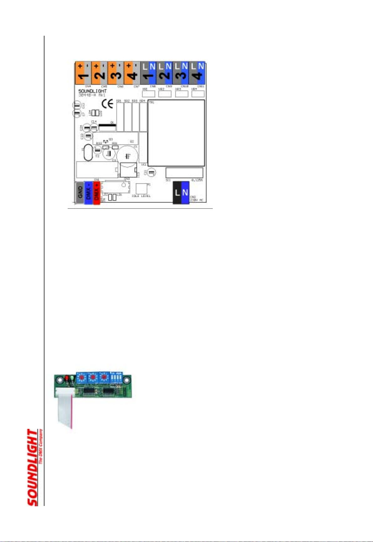
Connectpr Layout
pictured:layoutofconnectors3044B-H
Signal Indicators
Status signalling is with LED indicators:
green: DMX data reception OK
red: ERROR
normally off
blinks at transmission errors or at loss of signal
Start address
It is a commonly used scheme for building automation devices to avoid configuration switches. All
settings are stored permanently in non-volatile memory. When
installing the decoder for the first time, the DMX start address (number
of the first DMX data slot, value 001 ... 509) and decoder options must
be programmed.
The start address switch board 3000P is required to set start address
and mode of operation and decoder options.
NOTE! You do not need to open the 3044B-H interface to connect the start address
switch board. Before connecting the adaptor, disconnect the interface from
mains. Plug in the address board, then power up the interface again. Make
sure, that no parts of the address board are in contact with metallic parts.
This work should be carried out by a qualified technician only. If you do not
qualify, contact the factory or a factory representative to obtain a pre-
programmed decoder.

5
Decoder Options
NOTE: Using the new address setting board (order code: 3000P) will allow to set to set additional
parameters of the 3044B-H decoder. These functions include:
SWITCH #1 factory use only
SWITCH #2 OFF:Output to full ON when no DMX signal present
ON: Output to full OFF when no DMX sihnal present
SWITCH #3 OFF:4-channeloperation
ON: 1-channeloperation
SWITCH #4: OFF:mains relays switch when input > 0%
ON: mains relays deactivated
Control by DMX512
DMX512 will control four outputs, beginning with the programmed start address. Each output can be
operated individually. The start address can be set by the start address switch board. The unit may be
operatedwithorwithoutstartaddressboard(thenofcourseastartaddressmusthavebeensetbefore).
Electronic Ballasts (EVG)
Control of electronic ballasts is via connectors CN4-7. There is one connector pair per output, with the
common output being GND (white, resp. light grey connector) for all connected ballasts.
Usuallyterminalson theelectronicballastsaredesignated "+"and"-" , respectively.Then "-"willmean
GND. Please note that the maximum output current is limited to 25mA per output. This means,
assuming a control current of 1mA per ballast:
The number of ballasts per drive output of the 3044A must not exceed 25 units in parallel.
Iftheballastsrequiremoreinputdrivecurrentthenumberofballastsmustbeadjustedaccordingly,e.g.
assuming 0.5 mA per ballast will allow 50 units, 3mA per ballast will allow 8 units.
The ballasts can be powerd from the switched AC outputs. The maximum load per output must not
exceed200W(thatis3xballast58Wor5xballast36W).Ifbiggerloadsmustbeswitched,useacontactor
or relay being driven by the switched output of the 3044B-H..
Wiring of electronic ballasts shall only be performed by trained and skilled electricians. NOTE:
Interchanging power and data outputs will result in damaging connected components.
Please make absolutely sure that the wiring is correct before powering up the system!
6
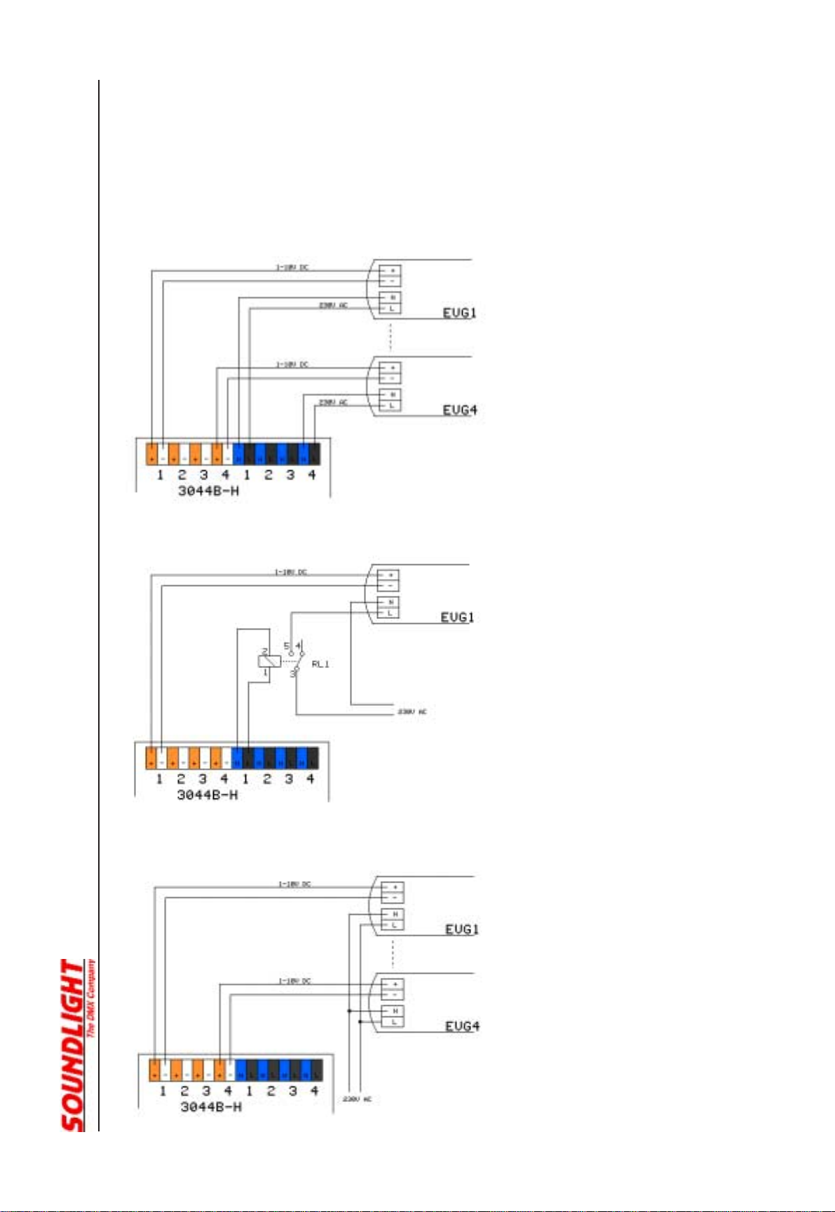
Power Supply of Ballasts
Electronicballastswith1-10Vcontrolinputusuallycannotbeshutdownviaconrolvoltage.Topoweroff
theballasts, the3044B-Hfeaturesfourswitchedpower outputs(connectorsCN8-CN11).Powerwill be
cutofwhentheassociatedDMXcontrolinputisdrivenwith000controlvalue.Theoutputwillbeactivated
for DMX data 001 thru 255 (01 hex to FF hex).
Schematic: individually powered and
switched ballasts
Schematic: heavy load switched by
additional contactor (use 230V AC relay, if
necessary, bypass with 0.22uF capacitor)
Schematic: ballasts not switched, powered
directly from mains

7
Technical Data
Dimensions: 86mm (W) x 113mm (D) x 68mm (H)
Piower Supply: 230 V AC
DMXIN: 1 Unit Load
DMXOUT: fed thru
Ballast Out: 1-10V DC Signal (current sink, max. 25mA)
Order Code: 3044B-H
Disturbances
If a trouble-free operation cannot be guaranteed, disconnect the decoder interface and secure it
against unwanted operation. This is especially necessary, when
- the unit has visible damages;
- the unit does not operate;
- internal parts are loose;
- connection cables show visible damages.
CE Marking
The unit has been tested in our lab and has been marked to comply with CE
requirements. To ensure compliance, use grounded power leads only and make
sure that properly shielded data lines (CAT5, DMX data cable or Digital Audio cable
to AES/EBU specifications) are used. Any modifications not approved by the
manufacturer may void CE compliance.
Limited Warranty
This instrument ist warranted against defects in metarials and workmanship for a period of 12
month, beginning with the date of purchase. The warranty is limited to repair or exchange of the
hardware product; no further liability is assumed. SOUNDLIGHT is not responsible for damages or
for loss of data, sales or profit which arise from usage or breakdown of the hardware product. In
germany, SOUNDLIGHT will repair or replace established defects in hardware, provided that the
defective part is sent in, freight paid, through the responsible dealer along with warranty card and/or
sales receipt prior to expiration of warranty.
Warranty is void:
- when modifying or trying to repair the unit without authorisation;
- modification of the circuitry;
- damages by interference of other persons;
- operation which is not in arccordance with the manual;
- connection to wrong voltage or current;
- misuse.
Service
There are no parts within the DMX DSI / DALI decoder 3004B-H which require the user's attention.
Should your unit require servicing, please send it to the factory, freight paid.

8
Internet-Hotline
Please check our internet domain http://www.soundlight.de for new versions, updates etc. If you
have any comments which may be worth considering, please send a message to
[email protected]. We will check your message and reply accordingly.
End-of-Liftetime Procedures
Electronicdevices are notdomesticwaste and mustbe disposedofproperly. If theend
of lifetime of this device has been reached, it must be recycled by the public electronic
devices recycling system.
SOUNDLIGHTisregisteredwithregistrationcodeDE-58883929forelectronic devices
recycling.
Table of contents
Other SOUNDLIGHT Media Converter manuals


