SOUNDLIGHT 3616PWM-H User manual

last updated: 17-10-24
OPERATING MANUAL
DMX / P M Decoder 3616P M-H Mk1.4 RDM
(C) SOUNDLIGHT 1996-2017 * ALL RIGHTS RESERVED * NO PART OF THIS MA-
NUAL MAY BE REPRODUCED DUPLICATED OR USED COMMERCIALLY WITHOUT
THE PRIOR WRITTEN CONSENT OF THE OWNER * ALL STATEMENTS WITHIN
THIS MANUAL HAVE BEEN CHECKED CAREFULLY AND ARE BELIEVED TO BE AC-
CURATE HOWEVER SOUNDLIGHT DOES NOT ASSUME ANY RESPONSIBILITY
FOR ERRORS OR OMISSIONS. * THE USER HAS TO CHECK THE SUITABILITY
OF THE EQUIPMENT FOR THE INTENDED USE. SOUNDLIGHT EXPRESSLY EXCLU-
DES ANY RESPONSIBILITY FOR DAMAGES - DIRECT OR INDIRECT - WHICH MAY
OCCUR DUE TO MISUSE UNPROPER INSTALLATION WRONG OPERATING CON-
DITIONS AND NON-COMPLIANCE TO THE INSTRUMENT'S INSTRUCTIONS AS
WELL AS IGNORANCE OF EXISTING SAFETY REGULATIONS.
SOUNDLIGHT
The DMX Company
Bennigser Str. 1 D-30974 Wennigsen Tel. 05045-912 93-11

Thank you for choosing a SOUNDLIGHT product.
The SOUNDLIGHT DMX PWM Converter 3616PWM-H is an intelligent converter accepting drive
signals according to USITT DMX-512/1990 DIN 56930-2 ANSI E1-11 DMX512A and ANSI E1-20
DMX RDM. The DMX signal is converted to a PWM output signal to drive low voltage incandescent
lamps or voltage driven (CV) LED arrays. 16 individual outputs are driven by up to 16 DMX addr-
esses. The interface can be used with all standard light control systems. Its special advantages inc-
lude:
-universal protocol decoding
Recognizes all variants of the protocol as defined by USITT / ESTA / ANSI/DIN
-future-proof
The unit is software controlled an can easily be adapted to any change in protocol.
-high linearity
As the unit accepts and outputs data in digital format excellent linearity chracteristics result.
-simple supply
The power supply is 12...24V DC (output voltage matches power supply voltage)
-signal loss
In the case of a loss of the drive signal the last setting will remain intact.
-cost-effective
The SOUNDLIGHT 3616PWM-H is a cost-effective solution for many purposes.
APPLICATIONS
The converter 3616PWM-H is intended for all control applications to drive voltage controlled loads
e.g. low voltage incandescent lamps or constant-voltage driven LEDs. Each output can be loaded
with 24V / 2 A / 50W@24VDC (absolute maximum rated values). The combined load of all outputs
must not exceed 16A.
The unit is well suited for all applications on stage for TV background lighting or for architectural
lighting purposes. The dimming range is 0% to 100%.
The 3616PWM-H is best suited to drive OSRAM LINEARLIGHT FLEX LED tapes.
Nomenclature
These symbols are used within this manual:
DANGER ! May cause harm to user and/or equipment
INFO: How to setup your device
INFO: Status information
UNPACKING
Please unpack carefully and check that all items are intact. When leaving our factory the interface
has been in good condition. In case of damage during transport please notify the carrier immediate-
ly.
When unpacking you should identify these items:
* the interface 3616PWM-H
* this manual
Please note that a start address programming adaptor (3000P) is NOT included with D N rail mount
devices. All settings can be performed using DMX RDM. Alternatively, a programming adaptor,
which can be used to set DMX start address, DMX personality and DMX HOLD mode, must be or-
dered separately. f you already have it, there is no need to buy again: the start address board
can be used for all our DMX interfaces, pcb and D N rail mount alike.
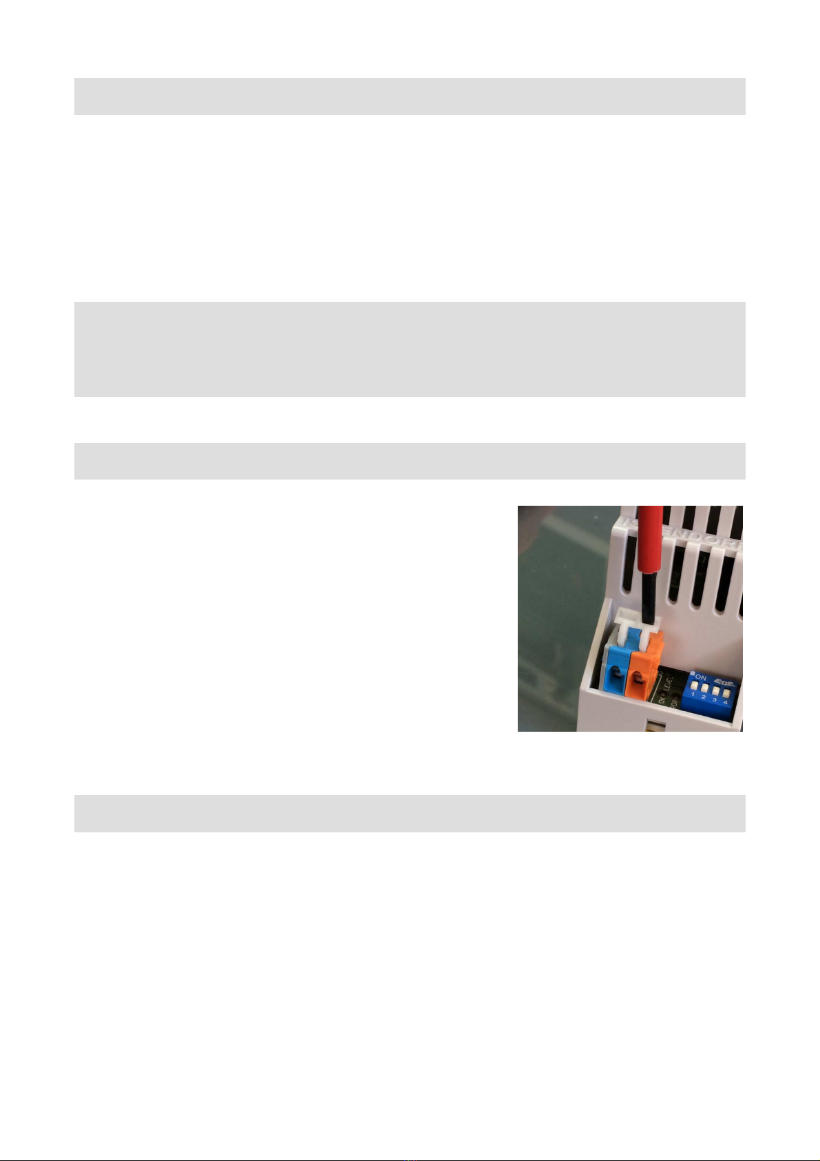
CAGE CLAMPS
The decoder 3616PWM-H consists of 6 terminal blocks. Ter-
minals are based on screwless WAGO cage clamp technolo-
gy which prevents loose connections and guarantees safe
electrical contact at all times. IMPORTANT: Use a standard
flat blade screw driver and press the lever to open the termi-
nal insert wire and release. Do not use a philipps or pozidrive
screwdriver to prevent damage ! Though both solid and
stranded wires may be used we recommend to use stranded
wires in combination with isolated ferrules whenever possible.
SI Peugruppe verwendet empfindliche elektronische Kompo-
nente
Please refer to the connector location outlined below.
CONNECTORS
The decoder 3616PWM-H comprises of these connectors:
(All terminal numbers: front view, left to right)
CN1 PO ER SUPPLY 24VDC
1 blue 0V DC (GND)
2 blue 0V DC (GND)
3 red +24V DC
4 red +24V DC
CN2 P M OUTPUT
1 grey CH 1: Drive Output -

2 grey CH 2: Drive Output -
3 grey CH 3: Drive Output -
....
16 grey CH 16: Drive Output -
CN3 DMX Data Input
1 grey GND Screen
2 blue DMX Drive Signal -
3 red DMX Drive Signal +
CN4 DMX Data Output
1 grey GND Screen
2 blue DMX Drive Signal -
3 red DMX Drive Signal +
IMPORTANT NOTICE: Outputs are short circuit protected using internal self-resetting
thermal fuses. Thermal fuses act slowly and allow high inrush currents.
SIGNAL INDICATORS
Status signalling is with LED indicators:
green: DMX
Steady: Data reception OK
Blinking: Start address error
red: ERROR
normally off
blinks at transmission errors or at loss of signal
yellow: RDM
lights when RDM programming active. Address switches are locked when RDM
programming is active. See chapter "RDM" for more info.
Red and green LEDs blink alternatively four times when programming data within the 3616PWM-H
(e.g. start address HOLD mode or change of DMX personality). No action will be taken when start
address setting is locked from RDM. See next chapter how to re-enable programming.
DMX START ADDRESS
To program a DMX start address simply set the de-
sired start address. Wait some seconds until the unit
recognizes and programs the address setting. The
programming cycle will be indicated by the the red
and green status LEDs flashing alternatively four times.
S3 S2 S1
CN1
CN2
CN4
CN3

The decoder can be operated with or without start address board connected. Please note that me-
chanical switches become disengaged and the respective settings are overridden when pro-
gramming is done via DMX RDM. To re-engage the switches set the hundreds position to „9“ tem-
porarily and wait for a programming cycle to complete. A programming cycle is indicated by the red
and the green LED blinking four times alternatively.
DIP-SWITCHES
The DMX personality (mode of operation) and the output behaviour is set using the four
DIP-switches of the start address board 3000P (or functions F1...F4 using the start add-
ress board 3003P):
DIP S ITCH 1,2 DMX HOLD MODUS S1 S2
Mode 0: no HOLD all outputs OFF OFF OFF
Mode 1: no HOLD all outputs ON OFF ON
Mode 2: DMX HOLD ("last look") ON OFF
DIP-Switch 1 DMX HOLD
OFF= see DIP switch 2
ON = DMX HOLD at data loss
DIP-Switch 2 OUTPUT LEVEL AT NON-HOLD
OFF= all outputs set to OFF at data loss
ON = all outputs set to ON at data loss
DIP-Switch 3,4 DMX PERSONALITY
Personality 1: S3=OFF S4=OFF 16-CH mode (smooth)
Personality 2: S3=OFF S4=ON 4-CH mode (smooth)
Personality 3: S3=ON S4=OFF 16-CH mode (fast)
Personality 4: S3=ON S4=ON 4-CH mode (fast)
The DMX Personality can also be set using DMX RDM.
DRIVE CHARACTERISTIC
The output drive characteristic follows a quasi-logarithmic law adapted to the human's eye sensitivi-
ty.
CONNECTING LEDs
You may connect voltage controlled LEDs directly.
Voltage controlled LEDs are LED assemblies which may be connected to a specified voltage (24V
DC) directly and incorporate measures to limit the operating current (e.g. TRIDONIC LED-Strips
OSRAM LINEARLIGHT FLEX). Such LEDs are commonly referred to as „CV“.
LEDs requiring a current control (e.g. LUXEON light sources OSRAM Golden Dragon etc.) must
be fitted with additional current limiting circuitry and are NOT suited for direct connection to the
3616PWM-H decoder.
Common LED terminal is the positive pin of the supply voltage ("Common Anode"). As high cur-
rents are present carefully check the wiring instructions and use sufficiant wire gauges. Outputs
are not short ir uit prote ted and must be fused externally.
WIRING INSTRUCTIONS
Please note:
At full load the total operating current can reach the rating of a single output cage clamp connec-
tor. Thus multiple GND clamps are provided to distribute the load to multiple wires.
- Only use a power supply with regulated DC output and appropriate current limiting.
- Feed the LED arrays
directly from the PSU (+24V DC)
- All GND terminals are interconnected.
Use one separate GND wire per connector.
- The electronics can be fed separately (+12...+24VDC) to allow operation even when the LED
PSU has been shut down.
- If needed insert external fuses 2A fast blow to prevent short circuit conditions.
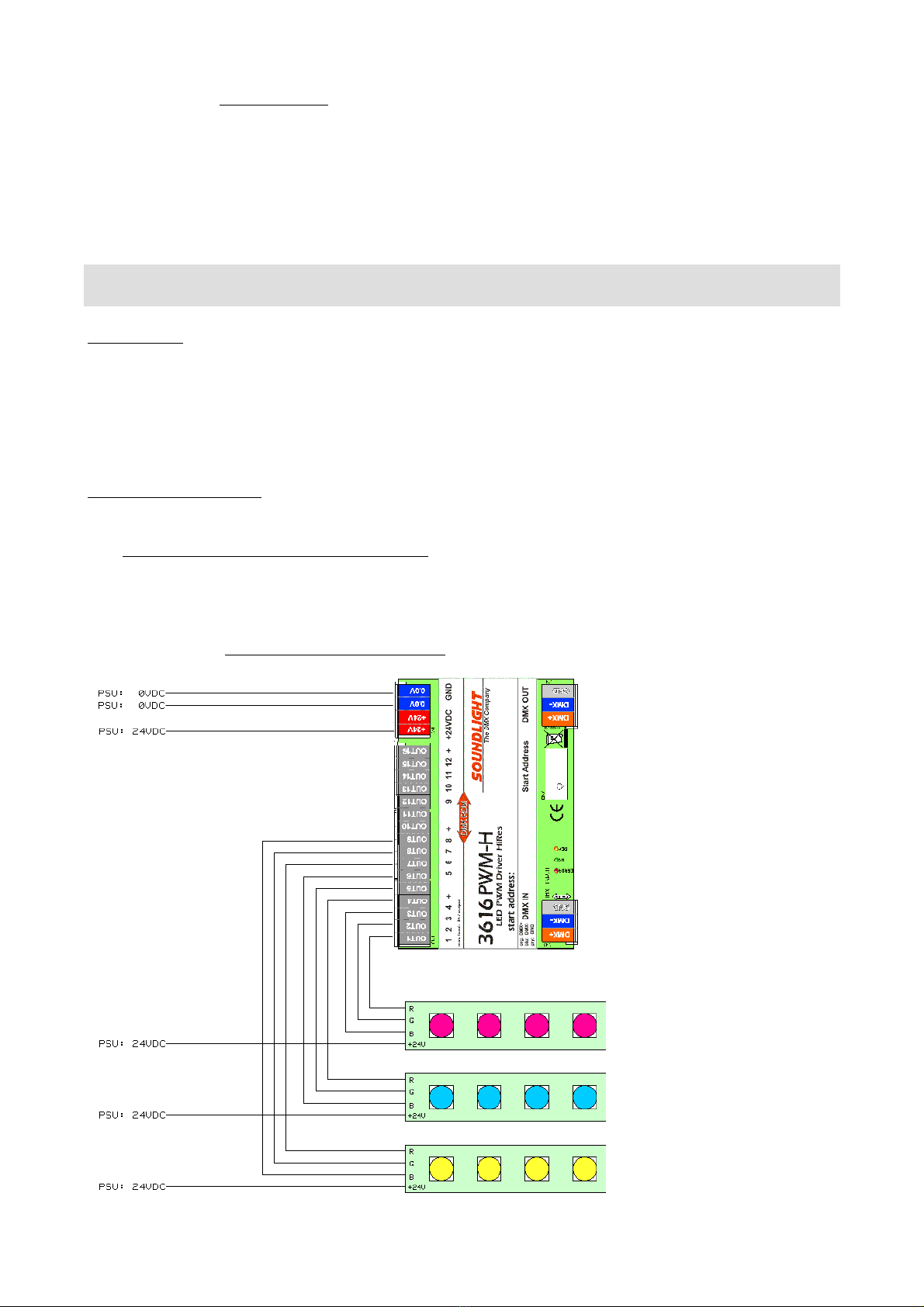
Typical wiring of 3616PWM-H when
used with multiple RGB strips.
Up to 5 common anode RGB strips or
4 RGBW strips can be connected.

TECHNICAL DATA
Dimensions: 114mm (W) x 93mm (D) x 66mm (H) width 6.5TE (units)
Power supply: 12 or 24V DC
DMX IN: 1 Unit Load
DMX OUT: fed-thru
DMX data slots: 16(4)
PWM Out: 12/24V pulse signal 0%-100%
PWM resolution: 12Bit
PWM characteristic quasi-logarithmic
Output Current: 1A per output
Absolute max. output current: 2A per output (internally limited: 2.5A thermal fuse slow blow)
Absolute max. output current: 16A (all outputs)
Output frequency: 520 Hz
Protection: IP20 - for dry rooms only
Operating temperature: 0-50 C
Order code: 3616PWM-H
DMX RDM
The 3616PWM-H is compatible with ANSI E1-20 DMX RDM Version 1.0. Please note some special
properties of devices complying with DMX RDM:
- DMX HOLD properties are not supported by RDM standard ANSI E1-20. A factory specific com-
mand (DMX HOLD) has been added to compensate these restraints. Use parameters 0...2 to set
the desired HOLD mode:
0: no HOLD all outputs OFF upon loss of signal
1: no HOLD all Outputs ON upon loss of signal
2: DMX HOLD (last look remains active)
- Setting the DMX personality reflects setting of DIP switches 3 and 4 (and vice versa).
Start adress setting using DMX RDM::
Please note that the 3000P start address switches get locked as soon as settings have been chan-
ged using DMX RDM. This prevents the decoder from reading start address switch data again.
To unlock the switches set the hundreds position to "9" temporarily. This will unlock the switches.
Additional RDM function allow to:
- read the DMX slot labels
- read and modify the device label
- identify the decoder
- read device hours and device initalizations
- read activate or deactivate the DMX HOLD mode
- monitor DC supply voltage

Recognizing the 3616PWM-H using Wireless DMX
RDM (Screenshot: CRMX Nova Software)
For more information or an in-depth command list see the RDM Manual available from our website
at www.rdm.soundlight.de or refer to the product website at:
www.soundlight.de/produkte/3616pwm-h .
DISTURBANCES
If a trouble-free operation cannot be guaranteed disconnect the decoder interface and secure it
against unwanted operation. This is especially necessary when
- the unit has visible damages;
- the unit does not operate;
- internal parts are loose;
- connection cables show visible damages.
CE MARKING
The unit has been tested in our lab and has been marked to comply with CE re-
quirements. To ensure compliance use grounded power leads only and make su-
re that properly shielded data lines (CAT5 DMX data cable or Digital Audio cable
to AES/EBU specifications) are used. Any modifications not approved by the ma-
nufacturer may void CE compliance.
FCC STATEMENT
This product has been tested and complies with the specifications for a Class B digital device pur-
suant to Part 15 of the FCC Rules. These limits are designed to provide reasonable protection
against harmful interference in a residential installation. This equipment generates uses and can
radiate radio frequency energy and if not installed and used according to the instructions may
cause harmful interference to radio communications.
However there is no guarantee that interference will not occur in a particular installation. If this
equipment does cause harmful interference to radio or television reception which is found by tur-
ning the equipment off and on the user is encouraged to try to correct the interference by one or
more of the following measures:
• Reorient or relocate the receiving antenna

• Increase the separation between the equipment or devices
• Connect the equipment to an outlet other than the receiver's
• Consult a dealer or an experienced radio/TV technician for assistance
FCC Caution: Any change or modification to the product not expressly approved by SLH could void
the user’s authority to operate the device.
LIMITED WARRANTY
This instrument ist warranted against defects in metarials and workmanship for a period of 24
month beginning with the date of purchase. The warranty is limited to repair or exchange of the
hardware product; no further liability is assumed. SOUNDLIGHT is not responsible for damages or
for loss of data sales or profit which arise from usage or breakdown of the hardware product. In
Germany SOUNDLIGHT will repair or replace established defects in hardware provided that the
defective part is sent in freight paid through the responsible dealer along with warranty card
and/or sales receipt prior to expiration of warranty.
Warranty is void:
- when modifying or trying to repair the unit without authorisation;
- modification of the circuitry;
- damages by interference of other persons;
- operation which is not in arccordance with the manual;
- connection to wrong voltage or current;
- misuse.
SERVICE
There are no parts within the DMX decoder 3616PWM-H which require the user's attention.
Should your unit require servicing please send it to the factory freight paid.
END OF LIFETIME
When the useful lifetime of this product has been reached it must be disposed of
properly. Electronic devices must not be placed in domestic waste. Consult your lo-
cal authorities to find the nearest collection point of used electric and electronic devi-
ces. SOUNDLIGHT is a WEEE registered company (Reg No. DE58883929).
ACCESSORIES
To set the DMX start address and change the operating parameters a DMX RDM controller or a
start address board is needed. These boards are optionally available:
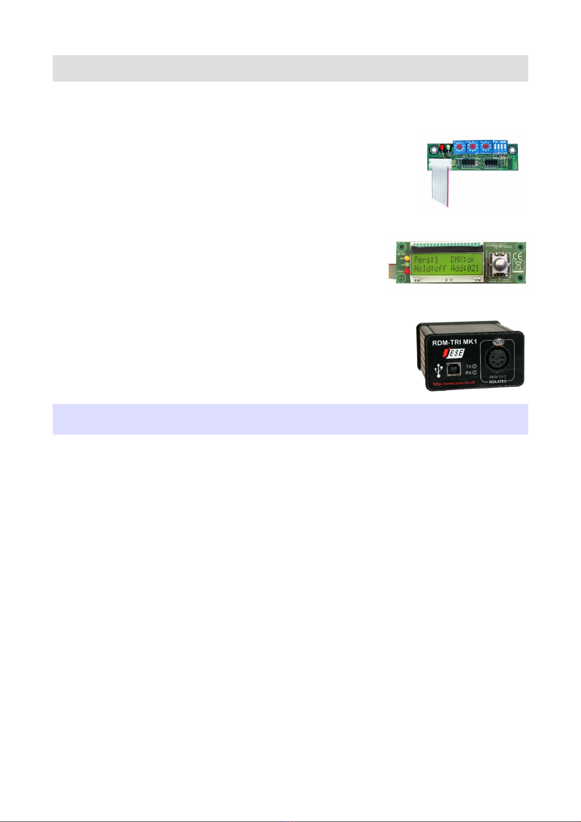
DMX START ADDRESS BOARD 3000P
www.soundlight.de/produkte/3000p
Three address BCD switches and a DIP switch to set operating parame-
ters. This is the standard board which is compatible wil all our decoders
(both pcb and DIN rail mount)
DMX START ADDRESS BOARD 3006P
www.soundlight.de/produkte/3006p
Start address board with LCD display and rotary encoder to set the
DMX start address. Adress is retained in nonvolatile onboard me-
mory.
DMX RDM CONTROLLER GET/SET USBRDM-TRI
www.soundlight.de/produkte/usbrdm-tri
Intelligent controller software for use on Windows machines. Complete
with USB connected interface connecting to DMX responders or introduce
RDM control when working with other DMX control gear.
Start address boards are not contained with DIN rail mount decoders and must always be ordered
separately!
Table of contents
Other SOUNDLIGHT Media Converter manuals


Popular Media Converter manuals by other brands

Asus
Asus Xonar Essence STU quick start guide

Siemens
Siemens SINAMICS G12 Hardware installation manual

Baumer
Baumer Hubner Berlin PMG 10 Proibus DP Installation and operating instructions

Link electronics
Link electronics HDC-925 Specification sheet

Soundfield
Soundfield UPM-1 user guide

Lindy
Lindy 43340 user manual


