Source SEM-CH-EXSIGN User manual

Installation &
Self Test Instructions
EMERGENCY HANGING BLADE
PRODUCT CODE: SEM-CH-EXSIGN
Quality
Assurance
years
Unit 7/8 Ashbourne Business Centre, Ballybin Road, Ashbourne, Co. Meath, Ireland, A84 YP58,
Phone: 00353 1 835 7447
Unit 32 Junction One Business Park, Valley Road, Birkenhead, Merseyside, UK, CH41 7ED,
UK Ph: 0330 551 7000
Website: www.sgd.ie
For more information contact:
Product end of life instruction.
This Lighting product is in the scope of EU 2019/2020 directive on Waste Electrical and Electronic Equipment
(WEEE). This product must be disposed of, according to the legislation. This document is intended for use by
end of life recyclers or treatment facilities. It provides the basic information to assure an appropriate end of life
treatment for the components and materials of the product.
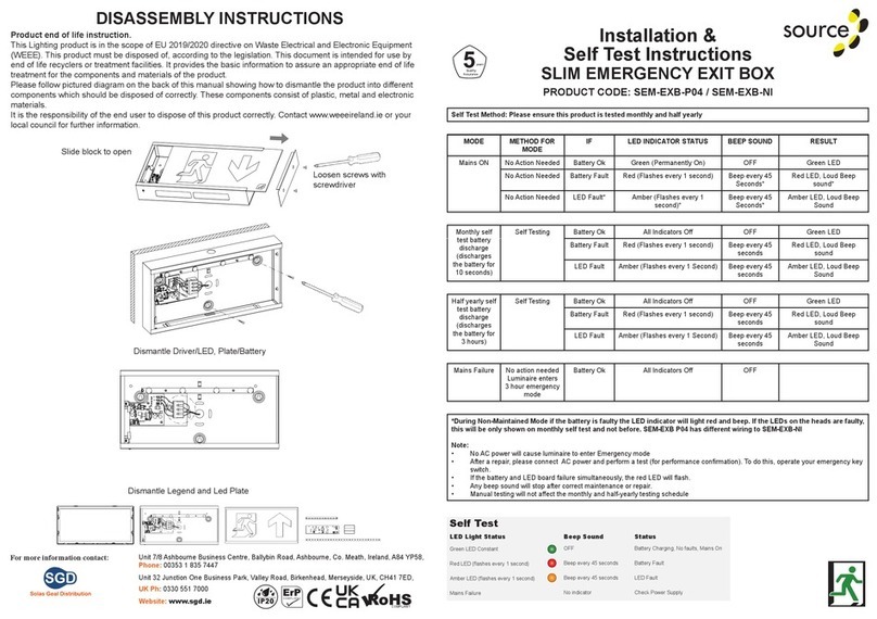
Please follow pictured diagram on the back of this manual showing how to dismantle the product into different
components which should be disposed correctly. These components would consist of plastic, metal and
electronic materials.
It is the responsibility of the end user to dispose of this product correctly. www.weeeireland.ie or contact your
local council for further information.
DISASSEMBLY INSTRUCTIONS
IP20
COMPLIANT
1 21 3
4
5!
Emergency Exit Sign surface suspended
AC 220-240V
x2
x1
x1
x1 x1
45285
300
35
185
160
700
x1
max. 45
1 2
N
L
Test
Please refer to this chart for more complete description / fault indication
Test Button Status
Green LED Constant Mains On / No Fault
Green LED Slow Flash Function for 2 minutes
Green LED Fast Flash 3 hour duration Test
Red LED 1 Flash Battery Fault
Red LED 2 Flash Lamp Fault
Red LED 3 Flash Duration Test Fault
Self-Test
Self-Test ttings perform a self-commissioning test at rst power on. After charging for 24 hours a full duration test (3 hours) is
performed. Initial function and duration tests are randomly generated.
They are then performed in accordance with standard requirements (every 30 days for function tests and every 52 weeks for
duration tests).
A single bi-colour indicator LED is tted in all Self-Test products. This LED is clearly visible for manual inspection. It indicates the
module status.
The LED shows permanent green or ashing green when conditions are normal and ashing red if a fault condition is present.
Function test
A function test is a 2 minutes test that simulates a mains failure and checks the operation of the emergency light source from the
battery supply.
The local indicator LED slow ashes green whilst the 2 minutes function test is in progress.
If there is a failure during a function test the local indicator LED changes to a ashing red.
Duration test
A duration test simulates a mains failure. It also checks the operation of the emergency light source from the battery supply for
the rated duration of the module.
The local indicator LED fast ashes green whilst the duration test is in progress.
If there is a failure during a duration test the local indicator LED either changes to ashing red.
The battery is required to be fully charged before a duration test can be started.
The test button of the unit has the following functions
Test Button Green LED Status
Press for about 1s Off Emergency mode for 1 second
Press for about 5s Slow ash Function for 30 seconds
Press for about 7s Fast ash 3 hour duration test
Press for about 10s End the duration test

Installation Instructions
• Provide power to the required point of installation, suitable IP rated junctions boxes should be used where required
• Mark the location of the xing holes and drill the holes ensuring not to infringe with any joists, gas or water pipes or electrical
cables
• Feed suspension cable through clamp
• Remove 2 screws on top of the tting (see g 1)
• This product can only be used in maintained operation (luminaire constantly on)
• Switch on the power supply and ensure the LED indicator is illuminated green. If it is not illuminated green, there may be a
battery fault
• The height of the sign can be adjusted via the compression clamp on the luminaire (see g 3)
Emergency Installation and Inspection
Serial/ Luminaire Number:
Installation / Test
Installed By: Date:
Record
Commissioned By: Date:
Year 1 Year 3*
*Recommended Battery Change LiFe P04
Year 4
Monthly test Signed Date Signed Date Signed Date Signed Date
1
2
3
4
5
6
7
8
9
10
11
12
Year 2*
*Recommended Battery Change NiCd
1 21 3
4
5!
Emergency Exit Sign surface suspended
AC 220-240V
x2
x1
x1
x1 x1
45285
300
35
185
160
700
x1
max. 45
1 2
N
L
Test
EMERGENCY TESTING
Recommended routine test procedures are in line with BS 5266 & BS EN 50172 & I.S3217:2013-A1:2017.
This product must be disconnected from the circuit if subjected to any high voltage or insulation resistance testing. Irreparable
damage will occur if this instruction is not followed.
Daily check - check that status GREEN LED indicator is illuminated
Monthly functional test - simulate a mains supply failure for approx. 30 seconds by operation of key switch or switching off circuit
breaker. Ensure normal supply is restored after test and ensure indicator status LED is illuminated
Twice yearly conduct a one hour duration test - simulate a mains supply failure for 1 hour continnously by operation of key switch
or switching off a circuit breaker. Ensure normal supply is restored after test and the indicator status LED is illuminated
Annual full 3 hour duration test - conduct a 3 hour duration test - simulate a mains supply failure for 1 hour continnously by
operation of key switch or switching off a circuit breaker. Ensure normal supply is restored after test and the indicator status LED
is illuminated
If the luminaire fails any of the above tests - please contact a qualied electrician.
All Emergency lighting tests must be logged. The Emergency lighting logbook must be provided in order to be covered by any
warranties.
These instructions should be read carefully and retained after installation by the end user for future
reference and maintenance.
These instructions should be used to aid installation of the following product:
EMLSUS
GENERAL INSTRUCTIONS:
SAFETY:
INSTALLATION:
• Installation of this luminaire should only be carried out by a qualified electrician or competent
person to the current IEE Wiring Regulations (BS7671) & current Building Regulations
• Please isolate mains prior to installation/maintenance
• Check the total load on the circuit, including when this luminaire is fitted, does not exceed the
rating of the circuit cable, fuse or circuit breaker
• Please note the IP (Ingress of Protection) rating of this luminaire when deciding the location for
installation
• This product is Class II double insulated
• This product is non-dimmable
• Provide power to the required point of installation, suitable IP rated junctions boxes should be used
where required
• Mark the location of the fixing holes and drill the holes ensuring not to infringe with any joists, gas
or water pipes or electrical cables
• Feed suspension cable through clamp
• Remove 2 screws on top of the fitting (see fig 1)
Remove screws
LED indicator (green)Test button
• Connect the battery to the inverter via the plug and socket provided
• Connect the Live and Neutral to the push fit terminals on the PCB of the inverter (Fig 2)
Fig1
Fig 2
Fig 3
• This product can only be used in maintained operation (luminaire constantly on)
• Switch on the power supply and ensure the LED indicator is illuminated green. If it is not
illuminated green, there may be a battery fault
• The height of the sign can be adjusted via the compression clamp on the luminaire (see fig 3)
Press this part of the clamp
to adjust the length
Can be adjusted to a maximum
length of 800mm.
Live (brown)
Neutral (Blue)
L
N
Suspension Mounting Flush Ceiling Mounting
MOUNTING OPTIONS

Declaration Number:
100-SEM CH EXSIGN
This declaration of conformity is issued under the sole responsibility of the manufacturer.
Products:
Emergency led Exit Hanging Blade 3W, IP20 6500K Maintained & Non-Maintained
Model Number:
SEM CH EXSIGN
The product/model of the declaration described above is in conformity with the relevant
Community harmonisation legislation:
Low Voltage Directive (2014/35/EU)
EMC (2014/30/EU)
The product/model of the declaration described above is in conformity with the standards
and technical specifications listed below:
EN60598-2-22:2014+A1, EN60598-1:2015+A1, EN62471:2008, EN62493:2015,
EN55015:2013+A1, EN61547:2009, EN61000-3-2:2014, EN61000-3-3:2013, BS EN
62034:2012
Signed 07/12/2022
Other Source Lighting Equipment manuals
Popular Lighting Equipment manuals by other brands

Somogyi Elektronic
Somogyi Elektronic home PNL 3/WH instruction manual
Lightolier
Lightolier Lightolier E1 Series Specifications
DTS
DTS DELTA 12 HEAD user manual

Somogyi Elektronic
Somogyi Elektronic home FLP 1600 SOLAR instruction manual
Eaton
Eaton FlexiTech Exit Dual AT L manual
Pilz
Pilz PSEN op4F/H-A Series operating manual
