Sourcetronic ST1778 User manual

SOURCETRONIC −Quality electronics for service, lab and production
0-20A DC BIAS Source ST1778
User Manual

- 2 -
Edition history:
The manual will be continually revised.
In case of errors or omissions, revision of device functions, as well as technological and software
upgrades, there will be corresponding adjustments and modifications of the manual.
February, 2014............................................................................................................ver1.0

- 1 -
Content
Chapter 1 General Information ...................................................................... 2
1.1 Introduction ................................................................................................................................................. 2
1.2 Basic Accuracy ............................................................................................................................................ 2
1.2.1 Accuracy Test Requirements....................................................................................................... 2
1.2.2 Current Accuracy........................................................................................................................... 2
1.3 Accessories .................................................................................................................................................. 2
Chapter 2 Panel Description.......................................................................... 3
2.1 Front Panel Description............................................................................................................................... 3
2.2 Rear Panel Description................................................................................................................................ 5
Chapter 3 Basic Operation ............................................................................ 6
3.1 Instruction of main interface........................................................................................................................ 6
3.1.1 Diagram and instruction............................................................................................................... 6
3.1.2 Tab diagram and function instruction......................................................................................... 8
3.1.3 Keyboard diagram and function.................................................................................................11
3.2 The output command................................................................................................................................. 12
3.2.1 Start............................................................................................................................................... 12
3.2.2 Stop............................................................................................................................................... 12
Chapter 4 Command interface......................................................................13
4.1 ST1778 RS232C........................................................................................................................................ 13
4.2 SCPI commands......................................................................................................................................... 13
4.2.1 General command set................................................................................................................ 13
4.2.2 ST1778 sub-system commands............................................................................................... 13

2
Chapter 1 General Information
1.1 Introduction
ST1778 DC Bias Current Source adopts high-performance MPU and can provide a constant current
ranging from 0A to 20A. The maximum current output can reach 0-120Aby connecting up to five slaves.
ST1778 can be used with most of Sourcetronic’s L meters and LCR meters. ST1778 provides a
convenient and practical DC Bias Current Source for AC+DC overlap inductor measurement and
magnetic material analysis.
1.2 Basic Accuracy
1.2.1 Accuracy Test Requirements
Within two year since factory calibration;
Environment temperature: 255°C;
Relative Humidity: ≤80%;
Power supply is regulated by a line-voltage regulator;
Warm up time: more than 15 mins.
1.2.2 Current Accuracy
Range (A)
Resolution (mA)
Accuracy
0.000~1.000
5
±(1%+5mA)
1.025~5.000
25
±2%
5.1A~20.0*n (n=1~6)
100
±3%
1.3 Accessories
Current output clip
The standard test clip and output line is ET-07-2 and ET-54. (Note: when the current is greater than 40A,
please do not use it as the current output.)
Footswitch
The standard footswitch is ST1801-001.
Link line
Each ST1778S slave is equipped with a SlaverLink.
Test Fixture
The standard high frequency test fixture is ST26004E-1.
3
Chapter 2 Panel Description
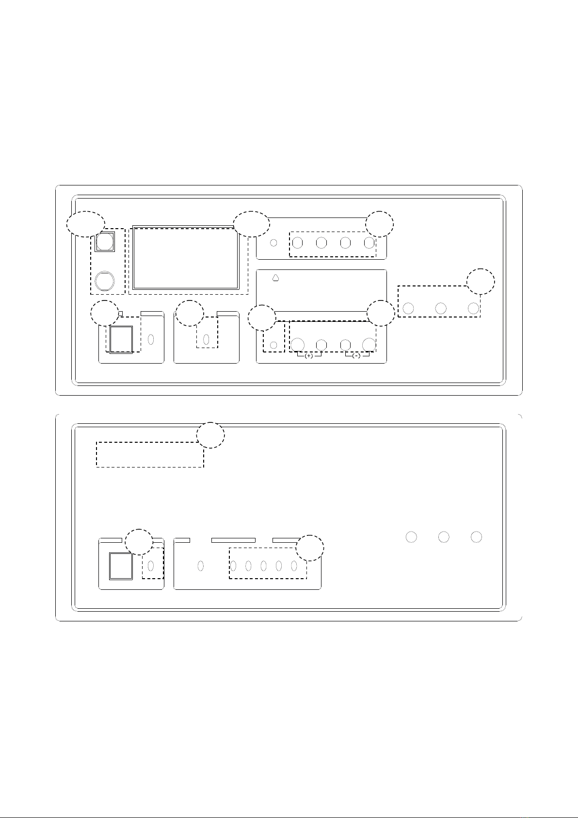
2.1 Front Panel Description
POWER DC BIAS
ON
BIAS CURRENT SOURCEST1778
ON
Achtung:
COM
HD HS LS LD
POTCUR
HPOT
H L CUR
L
GND
Lesen Sie vor Inbetriebnahme die Bedienungsanleitung.
Bei hohen Strömen kann es zu einer Abschaltung
aufgrund von Überhitzung kommen.
!
START
STOP
SINK SOURCE MG
O
_
Front panel of host machine
POWER DC BIAS
0-20A
BIAS CURRENT SOURCE
ST1778S
SLAVE
SINK SOURCE MG
ONON 1 2 3 4 5
O
_
Front panel of slave
1) Power Switch
When the switch is in the “I” position, all operating voltages are applied to the instrument. In the
“0” position, no operating voltages are applied to the instrument.
2) POWER LED
The power led is lightening after power on.
3) OUTPUT LED
When the instrument starts outputting, the output led of the main machine lights up; when the
10
11
7
8
5
6
3
2
1
4
9

4
output current of the slave reaches 20A, the output led of the slave lights up.
4) LOGO/MODEL
Logo and Model
5) OUTPUT PORT
6) GND
The GND terminal is tied to the instrument’s chassis. If using a three-phase socket, this GND
terminal is connected to the ground directly. If a large current fixture is used, this GND terminal
can be connected to that fixture in order to provide protection.
7) TEST INPUT
This port is used for connecting LCR or L meters, supplying the test signal and returning the
test access from the DUT through AC coupling.
8) TEST OUTPUT
This port is used for connecting the DUT, combining the signal load from the upper input port
and the bias current through the DUT.
9) SLAVE NO. LED
This led indicates the number of slave.
10) BUTTON
This button is used for controlling the start and stop of the current output manually.
11) SCREEN
This screen indicates the working condition of the instrument and it includes all the operation
functions via touch screen.
5
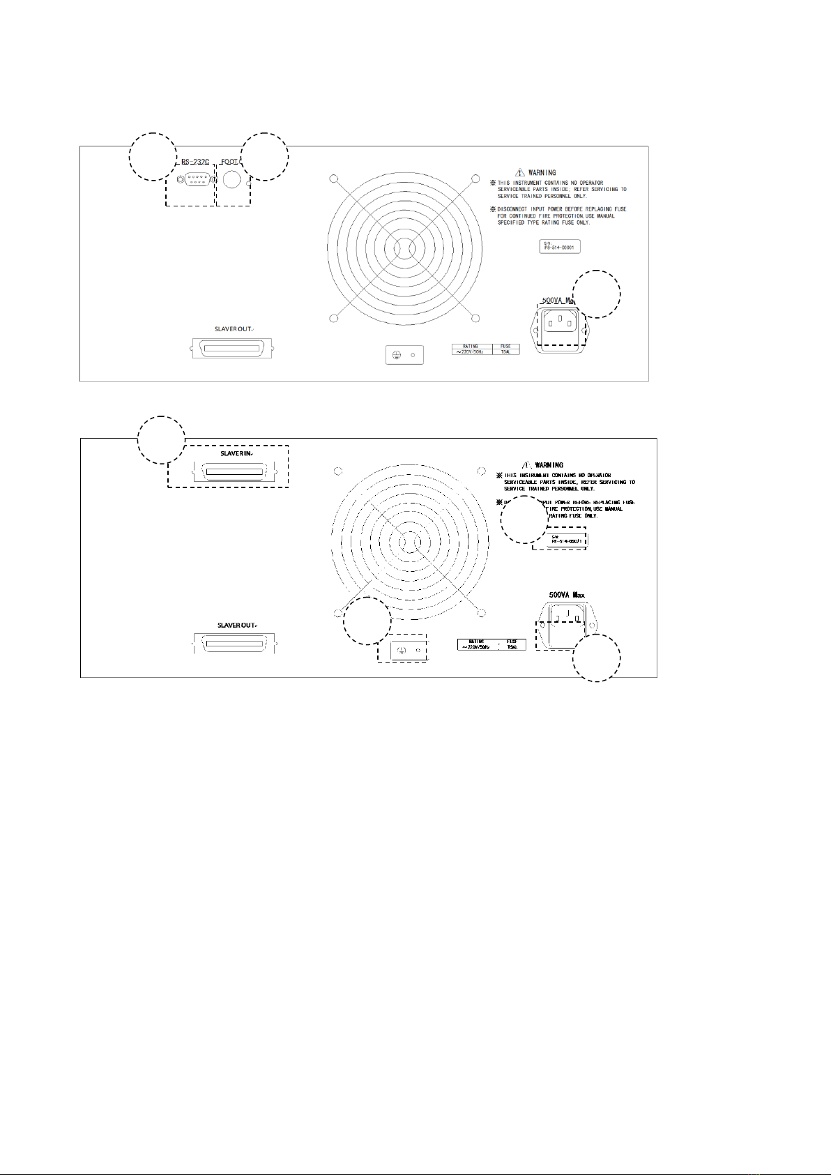
2.2 Rear Panel Description
Rear panel of host machine
Rear panel of slave
1) SERIAL PORT
Following the SCPI instruction set to control the output of the bias current and set its
parameters.
2) LINK PORT
The special link port for daisy-chaining slave devices.
3) FOOT CONTROL INPUT
Foot control input interface.
4) DATA PLATE
Provides the information of Serial number and name of manufacturer.
5) GND
Connect the ground lead.
6) FUSE SOCKET
Used for installing the power fuse to protect the instrument.
This instrument uses a 220V/5A fuse. If using foreign power, please replace the fuse to
110V/8A and change the internal electric source jumper.
7) POWER SOCKET
1
3
2
4
5
6
7
6
It is used for inputing theAC current. Please use the three-phase socket.
Chapter 3 Basic Operation
3.1 Instruction of main interface
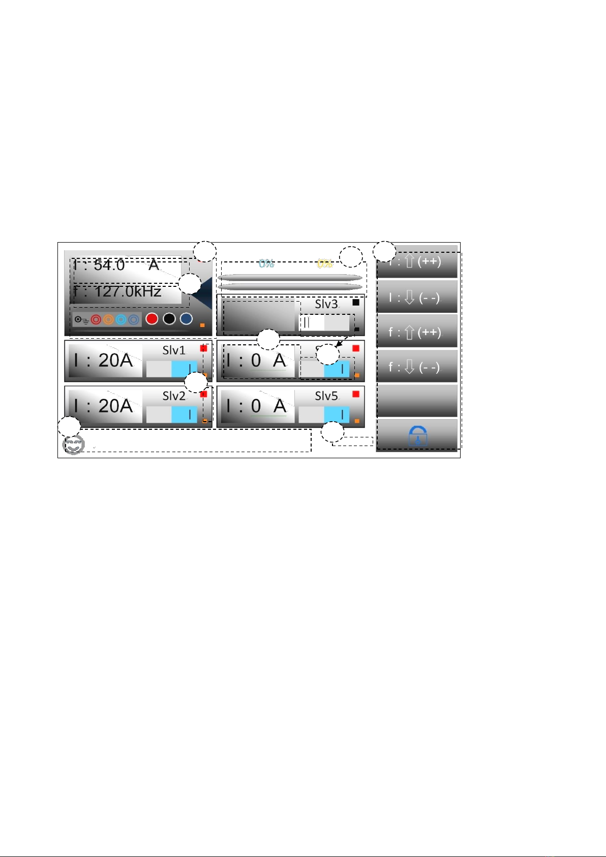
3.1.1 Diagram and instruction
1. In this zone, tap to enter the management windows, the detailed description follows in next part.
2. The primary and secondary parameters are displayed in this zone (Total current and frequency), tap it
to enter the current and frequency setting (The keyboard has calculating function, and supports dual
display and input-protection, which means double-confirm of input parameter). The detailed description
is in the next part.
3. Indication of output adjusting progress, after step-scanning, the light yellow percentage indicator
which is the first progress bar from the top will display the percentage of each adjustment, when the
instrument is operating, the first progress bar is used with light yellow color. When step scanning is off,
the bar will keep the default status, and the percentage will also keep 0%. The water blue indicator which
is the second progress bar from the top will display the percentage of total adjustment. When instrument
is operating, the second progress bar is used with water blue color. In either operating mode, even if the
output is started, the indicator will work.
4. Virtual keyboard, there are 5 functions from top to down: current increase, current decrease;
frequency increase, frequency decrease; blank ; lock and unlock touchscreen. In the page, if touch is
unlocked, all 5 keys can be used to 1 2 3 4 6 5 7 8 9 operate the tester, in any condition, Key 6 can be
used to lock and unlock the touch function
1
2
3
4
6
5
7
8
9

7
5. Sub-frame parameter display, when the slave is not powered or connected or not started up, the zone
is blank; when it is powered and connected, and user starts it up, the zone is lighted, also the value of
output current is displayed. Generally, the current is distributed automatically, if the slave is assigned as
one of the output drivers, then it displays 20A, if not, it is 0A.
6. Virtual switch, click the zone to switch on and off, if sky blue “I” is displayed, it means user has set the
slave as active, and when it is connected and powered, the display is as No. 5 above and LED indication
is as No 7 zone, then it will be included in the driver distribution; if gray “II” is displayed, it means the user
has deactivated this slave and it is not available for current distribution.
7. Virtual display LED displays the status of power supply and running state. The bigger LED indicates
the STATE, the smaller LED indicates the connection and POWER status; if the slave is not connected
or powered, then all LEDs are black; if the slave is connected and powered, but not activated by the user,
then only POWER is lighted; if there is no problem, user can use it as one of the distributed drivers; if all
is finished, then the display is like No.5. and the STATE LED is lighted; if this slave is not distributed or
system is not in output status, the LED is red; if the slave outputs current, the LED is green.
8. Real time clock display (RTC)
9. The zone display real time message; currently only 2 messages are supported to display now, if user
needs, we can add more.

8
3.1.2 Tab diagram and function instruction
Tab—parameter setting
Tab—file management
1
2
3
4
5
6
7
8
9
10
11
13
12
14
15
16

9
Tab—system setting
1. Label function, used to indicate the current label function.
2. Label, used to distinguish the current label and indicate the name, the current label is always on top, if
you want to switch, just click the naked zone to switch.
3. Close button, click to close the tab.
4. Functional icon for the current line, only for indication and click is allowed, after clicking, there is some
menu, like small keyboard or options .etc.
5. Parameter and content in current line, click is allowed, then there is an entity which can fit the
description in Zone No.4, foot control mode is not fit for the current description, so there is no any menu
or options.
6. External control button, the virtual button is only included in the parameter setting in figure 3.1.2.1, all
lines in this page include the buttons, and click any of it to get an external controlled options, the options
is fit as the description in Zone No.7.
7. Virtual external control key, only included in the parameter setting in figure 3.1.2.1, which is used to
control the increase and decrease of the parameter or switch, long press is allowed to fast increase and
decrease or switch.
8. File No. noted box, which can show the file No.
9. File name display, the file name can be revised in this zone.
10. File stored date and time display.
11. File noted box, when click, if there is file in this serial no. then you can make a note, otherwise, can’t.
Then there is a green tick in the noted file.
18
17
19
20
22
21

10
12. In this zone, there are virtual options and keys, the arrow key is used to turn the page or turn to the
front or end page. Other 5 options can be clicked to get the menu or functions. From left to right, there
are file storage, 18 17 19 20 22 21 file load, page no. and page switch, file search and delete functions.
13. Function menu, which will be pointed out in Zone No. 14.,15.,16.
14. In this zone, there is small input keyboard, which is used to obtain the file name, date, file no. After
the input is over, there is some notes whose description will be shown in zone No.15.
15. Click is available here, which contains the information input by user. If the box is green, it means
user has input information, if click this zone, then user’s information will be deleted.
16. The zone is virtual key, which is used to confirm or give up the inputted information.
17. Click is available in this zone, which is used to display the system setting and its status, after click,
there is optional menu, which is fit as Zone No. 18.
18. System setting menu, if click the zone out of the menu, it means user confirm the updated setting.
19. If click this zone, the switch is finished, the zone means virtual page up zone.
20. If click this zone, the switch is finished, the zone means virtual page-down zone.
21. Click there, it will show the date, if click, there is data setting keyboard.
22. Click there, it will show the time, if click, there is time setting keyboard.

11
3.1.3 Keyboard diagram and function
1
2
3
4
5
6
7
8
9
11
10

12
Keyboard—character
Keyboard—calendar setting
3.2 The output command
3.2.1 Start
1. Use START to control the output, long press can generate long pulse beeper.
2. Use foot switch to control the output, there are 5 modes, the mode can be revised in parameter
setting
Edge_U: Rising edge trigger
Edge_D: Falling edge trigger
Level: Level trigger
Hold: Hold the switch, it means output
3.2.2 Stop
1. Use STOP to control the output, long press to generate the long pulse beeper. When instrument is in
output status, press STOP to stop the output, and when the STOP key is pressed, instrument will cut the
internal relay to cut off the current path.
2. Use foot switch to stop the output.
Edge_U: Rising edge cut
Edge_D: Falling edge cut
Level: Level cut
Hold: Hold the switch, it means cut
17:23:45

13
Chapter 4 Command interface
4.1 ST1778 RS232C
As the most serial ports, ST1778 is not strictly based on RS-232, and uses only a minimal subset of the
9 pins. Only three wires are actually used:
Signal
Abbr.
Pin No.
Send data
TXD
3
Receive
data
RXD
2
Ground
GND
5
The connection of instrument and PC:
TXD(2)
PC RXD(3)
GND(5)
(2) RXD
ST1778
(3) TXD
(5) GND
As seen in the figure above, the pin definition of ST1778 is different from the 9-pin configuration in IBM
AT. Connection has to be 1:1, no crossover of Tx/Rx. Users can order a serial port cable from
Sourcetronic.
4.2 SCPI commands
<NR1> :Integer, as: 123。
<NR2> :fixed-point, as: 12.3。
<NR3> :floating point, as: 12.345……。
<LF> :Command terminator (Enter), which is 0x0A as a hexadecimal number or 10 in decimal. The
terminator should be added after all commands, otherwise, the instrument stays in waiting status. When
there is data returned, each data is terminated as <LF>.
4.2.1 General command set
*IDN?
Check the manufacturer, model, edition and firmware revision date. The returned format is as below:
“Sourcetronic,ST1778,V1.0.6,@2013.12”
*STA
Start the output.
*STO
Stop the output
4.2.2 ST1778 sub-system commands
The following is the root command set for the SCPI sub- system
●DEVIce ●MEMOry ●PARAmeter ●REMOte ●STATe ●SWITch ●SYSTem ●WORKing

14
1. DEVIce sub system command set
DEVIce is used to inform if ST1778 follows Sourcetronic standard with the communicated instrument.
Different settings will cause different system action: If Sourcetronic standard is used (TH), there is no
return if a parameter is changed; if switch to common mode (COMMon), all activity will be reported
back to the controller (default is common).
Command tree:
:MODEl control SCPI command
Command:DEVIce:MODEl <SCPI mode><LF>
<SCPI mode>:
COMMon set SCPI system as common mode, any activity from instrument will return
parameters, it is a default mode.
TH set SCPI system as Sourcetronic mode.
E.g :Send_Command(”DEVI:MODE TH”); set instrument to enter Sourcetronic mode
Return command: ”1778”
2. MEMOry sub system command set:
MEMOry sub system command set can realize the remote operation to local file system. The
separator can be any of “,.:-”, it will be expressed as <DELI> in the command tree, please note to
change it to one of the above allowed delimiters in real operation. In command tree, <NR1> should
be in the range of 1~99
Command tree:
:DELEte delete the file
Command: MEMOry:DELEte <number string><LF>
<number string>:
<NR1> 1~99
<DELI> separator“,.:-”
E.g.:Send_Command (”MEMO:DELE 1,5.16,21:34,75,94-97”); delete the file of No.1, 5, 16, 75, 16
to 21 and 94 to 97.
:SAVE save the current setting
Command: MEMOry:SAVE <number string><LF>
MEMOry—— :DELEte —— <NR1><DELI><NR1>…
:SAVE
:READ <NR1>
:LOAD
DEVIce:MODEl COMMon
TH

15
<number string>:
<NR1> 1~99
<DELI> separator“,.:-”
E.g.:Send_Command (”MEMO:SAVE 1,5.16,21:34,75,94-97”); save the file of No.1, 5, 16, 75, 16 to
21 and 94 to 97.
:READ read file
Command: MEMOry:READ <number><LF>
<number>:
<NR1> 1~99
E.g.:Send_Command (”MEMO:READ 5”); read the No.5 file, the description is as:
File head
Description
Format
Content
byte
Valid flag (dirty)
WORD
0 invalid/‘D’valid
2
Serial No. (No.)
WORD
1~99
2
(name)
STRING
‘0’~’9’/’A’~’Z’/’a’~’z’
16
(time)
TIME
‘0’~’9’&’-’&’:’
20
(addr)
DWORD
number
4
Total
44
File body
Description
Format
Content
(byte)
Current setting
MULTIPLE
ASCII
44
Frequency setting
MULTIPLE
ASCII
44
Step setting
MULTIPLE
ASCII
44
Delay setting
MULTIPLE
ASCII
44
Foot control setting
MULTIPLE
ASCII
44
Total
220
The details of each setting:
Single setting
Description
Format
Content
(byte)
Data
FLOAT
NUMBER
4
Name
STRING
’A’~’Z’/’a’~’z’
16
Character string
STRING
‘0’~’9’/’A’~’Z’/’a’~’z’
20
Chinese character addr.
MULTIPLE
ASCII
4
Total
44
:LOAD used to load the existed file
Command: MEMOry:LOAD <number><LF>
<number>:
<NR1> 1~99
E.g.:Send_Command(”MEMO:LOAD 5”); load No.5 file.

16
3. PARAmeter sub system command set
PARAmeter sub system command set is used to remote adjust the parameter.
Command tree:
:CURRent set the output current (unit:A), ”?” can inquire the current.
Command: PARAmeter:CURRent <number><LF>
<number>:
<NR3> 0.0~20.0*(n+1)(n means the quantity of slaves) floating number.
E.g.:Send_Command(”PARA:CURR 17.6”); set the current as 17.6A.
:DELaY set the time interval of scanning step(unit:ms), “?”can inquire the delay
Command: PARAmeter:DELaY <number><LF>
<number>:
<NR3> 0.0~3600000.0
E.g.:Send_Command(”PARA:DELY 100”); set the time interval of scanning step as 100ms。
:FREQuence set the frequency(unit:kHz), “?”can inquire the frequency
Command: PARAmeter:FREQuence <number><LF>
<number>:
<NR3> 0.0~2000.0
E.g.:Send_Command(”PARA:FREQ 300”); set the frequency as 300kHz.
:STEP set the step adjustment(unit:A), “?”can inquire the step
Command: PARAmeter:STEP <number><LF>
<number>:
<NR3> 0.0~20.0*(n+1)(n means the quantity of slaves) floating number.
E.g.:Send_Command(”PARA:STEP 2.1”); set the step as 2.1A。
:FOOT set the foot control mode(there are 5 modes), “?”can inquire the mode
PARAmeter —— :CURRent —— <NR3>
:DELaY
:FREQuence
:STEP
:FOOT EDGeD
EDGeU
HOLD
LOCKed
VOLTage

17
Command: PARAmeter:STEP <string><LF>
<string>:
EDGeD set the valid mode as down edge
EDGeU set the valid mode as up edge
HOLD set the valid mode as hold
LOCKed set the mode as lock, it means turn off
VOLTage set the mode as level
E.g.:Send_Command(”PARA:FOOT EDGD”); set the mode as down edge trigger
4. REMOte sub system command set
REMOte sub system command set is used to remote control the lock and unlock of system
Command tree:
Command: REMOte <string>
<string>:
LOCKed
UnLOCked
E.g.:Send_Command(” REMO ULOC”); unlock the system
5. STATe sub system command set
STATe sub system command set is used to remote inquire the state of host and system.
Command tree:
:HOST inquire the state of host, add“?” at the end.
Command: STATe:HOST?<LF>
E.g.:Send_Command(”STAT:HOST?”); obtain the state of host.
Definition of returned data (include a byte):
When the following bit is 1, it means the state is on or valid
Bit1: if charge
Bit2: if working
Bit3: if over heat
Bit4: if over load
STATe —— :HOST
:WORKing
:SLAVe——<NR1>,<NR1>…
REMOte—— LOCKed
UnLOCked

18
Bit5: if unbalance
Bit6: if set this set
:WORKing obtain the working state, add “?”at the end.
Command: STATe:WORKing?<LF>
E.g.:Send_Command(”STAT:WORK?”); obtain the working state.
Definition of returned data:
“preparing”: the system is in prepare
“stop”: the system is in stop, waiting for trigger or other thing happen
“running”: system is in output state
:SLAVe obtain the state of slave, add“?”at the end.
Command: STATe:SLAVe <string>?<LF>
<string>:
<NR1> 1~5
“,” ID character
E.g.:Send_Command(”STAT:SLAV 1,2,5?”); obtain the state of slave no.1, 2, 5.
Definition of returned data (each slave includes 2 bytes):
When the following bit is 1, it means the state is on or valid (each byte should deduct ASCII
character’0’, then can get the real data)
Bit1: if charge
Bit2: if working
Bit3: if over hear
Bit4: if over load
Bit5: if unbalance
Bit6: if setup the set
6. SWITchsub system command set
SWITchsub system command set is used to check if user has started the setting of slave
Command tree:
:SLAVe control the state of slave
Command: SWITch:SLAVe <string>
<string>:
:TurNOfF turn off the slave
Command: SWITch:SLAVe:TurNOfF <string>
<string>
NR1 1~5
“,” ID Interval
E.g.:Send_Command(”SWIT:SLAV:TNOF 1,2,5?”); turn off the slaves No. 1, 2, 5.
:TurNON turn on the slave
Command: SWITch:SLAVe:TurNON <string>
<string>:
SWITch——:SLAVe——:TurNOfF——<NR1>,<NR1>…
:TurNON
Table of contents
Popular Laboratory Equipment manuals by other brands

SynOptics
SynOptics SYNBIOSIS Protos 3 quick guide

Lightmed
Lightmed TruScan Pro Operator's manual

DENTAURUM
DENTAURUM 090-606-00 Instructions for use

FuturaSun
FuturaSun ZEBRA Pro Series Safety and installation manual

Fisher Scientific
Fisher Scientific fisherbrand 850 user manual

Infors HT
Infors HT Labfors 5 operating manual


