asecos GAP User manual

EN
EP.V.35906.01 | 02/2024
USER MANUAL
Hazardous Materials Work Stations

GAP.140.090.WA
GAP.140.120.WA
GAP.140.090.EX
GAP.140.120.EX
GAP.140.180.EX
GAP.110.090.060
GAP.110.120.060
GAP.110.150.060
GAP.110.180.060
GAP.110.210.060
GAP.110.240.060
GAP.110.090
GAP.110.120
GAP.110.150
GAP.110.180
GAP.110.210
GAP.110.240
GAP.140.090.060
GAP.140.120.060
GAP.140.150.060
GAP.140.180.060
GAP.140.210.060
GAP.140.240.060
GAP.140.090
GAP.140.120
GAP.140.150
GAP.140.180
GAP.140.210
GAP.140.090.EC
GAP.140.120.EC
GAP.140.150.EC
GAP.140.180.EC
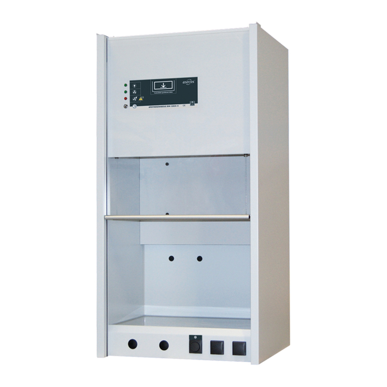
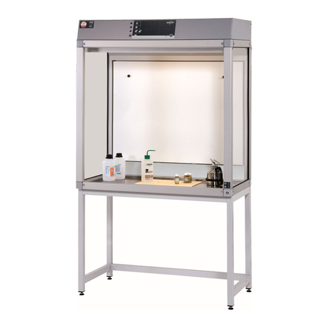
Hazardous materials work stations GAP
Hazardous materials work
stations GAP – Weighing work
station
Hazardous materials work
stations GAP– EX-LINE


4
EN OPERATING INSTRUCTIONS
Dear customer,
These operating instructions are for practical use and should be available to the user where the hazardous
material workplace is to be used.
Please keep these operating instructions close to the unit. An assured, faultless functioning of the hazardous
material workplace is only ensured when these instructions are followed. Do take note of the safety informa-
tion.
Many thanks.
Your asecos team
1. NOTES • GUIDELINES • GUARANTEE ...........................................5
1.1. General safety notes ............................................... 5
1.2. Guarantee........................................................ 5
1.3. Details .......................................................... 5
2. ERECTION • COMMISSIONING ................................................5
2.1. Assembly of the support frame (width up to 1800 mm)................... 5
2.2. Assembly of the support frame (width 1800 mm)........................ 6
2.3. Assembly of front and side panel ..................................... 6
2.4. Alignment of the workplace.......................................... 7
2.5. Commissioning.................................................... 7
2.6. Turn on and turn off................................................ 8
2.7. Installation of the monitoring electronics ............................... 8
2.8. Earthing possibility ................................................. 9
3. POTENTIALFREE SWITCHING CONTACT / POTENTIALFREE ALARM CONTACT OPTIONAL
9
3.1. Connection of the potential-free switching contact ....................... 9
3.2. Connection of the potential-free alarm contact (optional)................. 10
4. FUNCTION................................................................11
4.1. Mode of operation .................................................11
4.2. Optional media duct/media socket................................... 12
5. VENTILATION ADJUSTMENT • MONITORING....................................13
5.1. Ventilation ...................................................... 13
5.2. Monitoring ...................................................... 13
6. MALFUNCTIONS • ACTIONS .................................................14
7. CONNECTION TO A MEDIA SUPPLY ...........................................14
7.1. Connection in the media duct....................................... 14
7.2. Connection in the media socket ..................................... 14
8. FUNCTIONAL CHECK • MAINTENANCE • CARE ..................................14
9. DOKUMENTATION GAP EXLINE KOMPONENTEN ...............................15
10. TECHNICAL DATA ..........................................................16

5
EN
1. NOTES • GUIDELINES • GUARANTEE
1.1. GENERAL SAFETY NOTES
• Observe the notes in these operating instructions!
• Observe applicable statutes and regulations, and the notes in these operating instructions, when handling
hazardous materials
• Observe accident prevention regulations and workplace ordinance
• Ensure that the necessary safety checks are only carried out by authorised sta using original
spare parts
• Only use the hazardous material workplace in a proper condition
• Make sure that there are no air currents above 0.2 m/s when selecting the place of erection as this can aect
the functional apability.
• The users are to be trained on handling of the hazardous material workplace
• The required exhaust air flow is to be provided on site
• Observe the maximum weight with which the cabin may be loaded
• Any hazardous materials that escape must immediately be collected and removed
• Please check the material resistance of all surfaces for the use of aggressive materials.
• The instructions of the supervisory engineering department must be followed.
• Elektroinstallationen bzw. Anschlussarbeiten an elektrische Anlagen und Betriebsmittel dürfen nur durch eine
Elektrofachkraft vorgenommen werden.
1.2. GUARANTEE
The warranty for this product is agreed between you (the customer) and your specialist dealer (the seller).
asecos, as the manufacturer, provides a warranty of 24 months from the date of delivery for the products list-
ed in the operating instructions. As a safety device, all models are subject to an annual inspection by specialist
personnel authorised by the manufacturer. All device connections, including electrical and media connections,
must be made exclusively at the transfer points provided by asecos. Failure to do so will invalidate the custom-
er’s warranty claim against the manufacturer.
1.3. DETAILS
Development: asecos GmbH Sicherheit und Umweltschutz, D-63584 Gründau.
Serial No.: inside the hazardous substance workplace on the air duct
Hazardous material workplace GAP
Complete capture of hazardous vapours, gases or suspended solids at the place where they emerge or where
they are created before they can have eects that are damaging to health or to the environment (see hazard-
ous materialsregulations, workplace regulations and laboratory guidelines)..
Hazardous material workplace GAP
Complete capture of hazardous vapours, gases or suspended solids at the place where they emerge or where
they are created within explosive atmospheres of zone 1, before they can have eects that are damaging
to health or to the environment (see hazardous materials regulations, workplace regulations and laboratory
guidelines).
2. ERECTION • COMMISSIONING
2.1. ASSEMBLY OF THE SUPPORT FRAME WIDTH UP TO 1800 MM
6
4
6
4
4
!3
2

6
EN
3
2
2
4
4
5
2.2. ASSEMBLY OF THE SUPPORT FRAME WIDTH 1800 MM
8
4
8
4
4
!3
2
3
1
1
!
5a
5b
4
5a
5b
3
3
6
4
7
2.3. ASSEMBLY OF FRONT AND SIDE PANEL

7
EN
!
2.1
2.2
8
4
2
x
3
a
b
4
CLICK
5
2.4. ALIGNMENT OF THE WORKPLACE
–10 mm
max.
+30 mm
with support frame
(optional)
23
2.5. COMMISSIONING
Testing before setup:
- Adequate ground loading capacity.
- Point loads on the 4 supports of the frame (technical data)!
- Make on site extraction air connection
250
1
NOTE
The PVC reducing spigot for reducing from 250 mm to 200 mm is
available separately (order number 41046 EP.K.35344). Please contact

8
EN GAP /Weighing work station
230 V 1
2
TEST
3
GAP EX-LINE
230 V
1
TEST
2
3
2.6. TURN ON AND TURN OFF
GAP /Weighing work station
1
GAP EX-LINE
2
1
TEST
2
3
4
2.7. INSTALLATION OF THE MONITORING ELECTRONICS
ATTENTION
The monitoring electronics unit is to be installed outside potentially explosive atmospheres only
All work must be carried out by a qualified electrician!
3
2
1
1
4
B
A
32
1
2
• Connect all components on the headboard of the hazardous materials workplace [Fig 1] with the appropriate
connection on the control unit of the monitoring electronics [Fig 2]
Slot 1 - Dierential pressure switch
This pressure switch must be connected electrically to the external electronics by connecting the blue cable to
the monitoring electronics unit
Slot 2 - Lighting
Connect the other ends to the explosion-proof lamp (black cable).
Slot 3 - Fan
Please, make a connection between the fan and the suitable slot on the monitoring electronics unit using the
black cable.

9
EN
Slot 4 - Mains connection
Insert the mains cable into an available 230 V mains socket
Optional connections
Connection A - Potential-free switching contact
To use the switching contact, e.g. to control on-site exhaust air systems, please refer to point 3.
Connection B - Potential-free alarm contact
If available, use the supplied plug and please note point 3.
2.8. EARTHING POSSIBILITY
12
3. POTENTIALFREE SWITCHING CONTACT / POTENTIALFREE ALARM
CONTACT OPTIONAL
3.1. CONNECTION OF THE POTENTIALFREE SWITCHING CONTACT
Each hazardous substance workstation includes a potential-free switching contact for connecting and con-
trolling on-site consumers such as exhaust air systems, “Operation” indicator light..
Technical data
• Rated voltage: max. 400V
• Rated current: max. 25A
Switching contact position
for operation top view
hazardous materials workstation
and weighing workstation
side view
monitoring electronics
EX-LINE

10
EN Supply voltage incl. on-site
fuse protection
Consumer e.g. fan
Control electronics
3.2. CONNECTION OF THE POTENTIALFREE ALARM CONTACT
OPTIONAL
The alarm contact is used to indicate a fault in the device. The contact is designed for a maximum direct volt-
age of DC 30 V or an alternating voltage of AC 230 V. The maximum current carrying capacity is 10 A.
Alarm contact position
(optional) top view
hazardous materials workstation
and weighing workstation
side view
monitoring electronics
EX-LINE

11
EN
NOTES
Use outside the above parameters is not permitted for safety reasons.
------
The alarm contact must not be confused with other contacts. The installation plug of the corresponding
contact is labelled for this purpose.
------
If the labelling of the alarm contact is not recognisable, it must not be connected or operated. The asecos
GmbH service department must be notified in order to replace the labelling.
------
Only the supplied counterpart to the installation plug (on the device) is to be used for connection.
------
The switching contact / alarm contact must be protected on site with a fuse (see illustration), which limits
the current to the maximum switching current specified above.
(AC) / (DC)
(AC) / (DC)
Connector
Internal
alarm contact
4. FUNCTION
4.1. MODE OF OPERATION
CAUTION
Avoid negative infl uences on the fl ow behaviour in the hazardous material workplace due to:
›Incorrect operation (i.e. no fast movements > 1m/s)
›more aspects:

12
EN
4
72
3
5
6
1
4
Air entering through the front
opening
Radial fan air intake
Aluminium tubular fame
Upper/lower fresh air
curtains: take away any gases,
vapours, suspended solids
towards the deflector
Deflector
Work surface
Exhaust air
4.2. OPTIONAL MEDIA DUCT/MEDIA SOCKET
Earthed sockets
Width 90—150 cm
230 V
Width 180—240 cm
230 V
Position terminal box
Front view
Top view
NOTE:
For on-site connection and fuse protection, please observe the respective country standard.

13
EN
Media supply
5. VENTILATION ADJUSTMENT • MONITORING
5.1. VENTILATION
PLEASE NOTE!
factory setting of the inlet air flow, recommended exhaust air flows and pressure losses: see technical data!
The specified values don’t apply if another setting is selected!
• Ecient, secure retention of the pollutants at the hazardous material workplace is achieved through an opti-
mum combination of inlet and exhaust air.
• The retention capacity of the hazardous material workplace depends on the inlet air speeds of the device.
• An increase in inlet air fl ow is only possible with an increase in exhaust air fl ow, otherwise any pollutants may
be forced out of the hazardous material workplace.
• The appliance has been optimised at the factory.
• In the case of hazardous substance workplaces with more than one exhaust air spigot, each exhaust air spigot
is monitored separately. It is therefore necessary for each spigot to be vented evenly.
• A delay of 20 seconds is set at the factory for exhaust air monitoring so that the on-site exhaust air system can
build up the necessary negative pressure before the test, even if the exhaust air line is longer.
5.2. MONITORING
Monitoring electronics
a
b
c
aPower supply OK – illuminates permanently
bVentilation OK – illuminates when ventilation is turned on
cVentilation ERROR – illuminates in case of malfunction
• Pressure measurement in exhaust and inlet air duct with integrated pressure cell and set point (minimum
nominal air flows X)
Deviation from nominal
values X
X=90%
1
2
3
Nominal values X are
reached
X=100%
1
3
2
NOTE for GAP EX-LINE models
The button for resetting the alarm is located on the monitoring electronics.

14
EN POWER FAILURE:
Operation of the monitoring electronics unit with built-in even battery even in the case of a power failure.
6. MALFUNCTIONS • ACTIONS
a
b
c
MALFUNCTION ACTION
the mains plug is inserted
adoes not illuminate
Check if there is power on the socket in use
the On/O switch had been activated
bdoes not illuminate
LED defective (replace) or
defect in the electronics
The light does not switch on after the self-test. Contact Service
cilluminates during operation of the workplace Check the pressure dierence on the on-site exhaust
air pipe (see point 5) or defect in the integrated
supply air fan.
3 short beeps sound every 60 seconds
cshortly lluminates every 20 seconds
Power failure
CAUTION
If your hazardous material workplace has the above or other defects, then please contact your dealer.
7. CONNECTION TO A MEDIA SUPPLY
7.1. CONNECTION IN THE MEDIA DUCT
Below worktop
4×20 TX20
1
20 cm
2
3
G 1/2
4
7.2. CONNECTION IN THE MEDIA SOCKET
On backpanel
1
G 1/2
2
3
8. FUNCTIONAL CHECK • MAINTENANCE • CARE
Continuous functional testing of the hazardous material workplace
• during operation through the integrated ventilation monitoring unit (item 4)
Annual maintenance and functional test
• by specialised sta authorised by asecos

15
EN
Cleaning
• with normal mild household cleaners
• escaped fluids should be collected /removed immediately
Cleaning of deflector
1
2
3
CONTACT:
In the case of defects or complaints about our products (within and also after the warranty period), and for
requesting safety checks or taking out a service contract, please contact our service hotline on:
Tel: +44 1785 22 70-90 | info@asecos.co.uk (for great Britain and Ireland)
Tel: +49 1805 92 20 92 | service@asecos.com (international)
9. DOKUMENTATION GAP EXLINE KOMPONENTEN
NOTE
All documents relating to the components installed in the GAP EX-LINE can be obtained using this QR code.

16
EN
All hazardous materials work stations have the following electrical connection data:
Rated voltage 230 V 50 Hz.
Power consumption 70-150 W (depending on device size)
10. TECHNICAL DATA
Key for “Technical data” table
1Height (external) 11 Depth usable work surface with media duct
2Height with support frame for sitting work 12 Depth (external)
3Height with support frame for standing work 13 Depth (internal)
4Work height sitting 14 Max. charge of the working surface
5Work height standing 15 Weight
6Clear height 16 Noise level (approx.)
7Width (external) 17 Dierential pressure per air duct
8Width (internal) 18 Amount of air ducts
9Width usable work surface 19 Extraction air
10 Depth usable work surface 20 Nominal volume flow
11 12 13 14 15 16 17 18 19 20
GAP.110.090 530 750 650 3000 66 32.0 82 1 250 550
GAP.110.090.060 380 600 500 3000 60 32.0 82 1 250 550
GAP.110.090.085 630 850 75 0 3000 70 32.0 82 1 250 550
GAP.110.120 530 750 650 3000 75 32.0 60 1 250 550
GAP.110.120.060 380 600 500 3000 69 32.0 60 1 250 550
GAP.110.120.085 630 850 75 0 3000 79 32.0 60 1 250 550
GAP.110.150 530 750 650 3000 84 36.0 77 1 250 660
GAP.110.150.060 380 600 500 3000 77 36.0 60 1 250 660
GAP.110.150.085 630 850 75 0 3000 88 36.0 60 1 250 660
GAP.110.180 530 750 650 3000 93 36.0 70 1 250 770
GAP.110.180.060 380 600 500 3000 85 36.0 70 1 250 770
GAP.110.180.085 630 850 75 0 3000 97 36.0 70 1 250 770
GAP.110.210 530 750 650 3000 116 40.0 55 2 250 880
GAP.110.210.060 380 600 500 3000 108 40.0 50 2 250 880
GAP.110.210.085 630 850 75 0 3000 120 40.0 55 2 250 880
GAP.110.240 530 750 650 3000 116 40.0 50 2 250 990
GAP.110.240.060 380 600 500 3000 107 40.0 50 2 250 990
GAP.110.240.085 630 850 75 0 3000 121 38.0 50 2 250 990
GAP.140.090 530 750 650 3000 76 32.0 140 1 250 720
GAP.140.090.060 380 600 500 3000 70 32.0 140 1 250 720
GAP.140.090.085 630 850 75 0 3000 81 32.0 140 1 250 720
GAP.140.090.EC 530 750 650 3000 78 32.0 82 1 250 550
GAP.140.090.EX 530 750 650 3000 94 55.0 140 1 250 720
GAP.140.090.WA 530 750 650 3000 76 32.0 82 1 250 550
GAP.140.120 530 750 650 3000 86 32.0 103 1 250 720
GAP.140.120.060 380 600 500 3000 80 32.0 103 1 250 720
GAP.140.120.085 630 850 75 0 3000 92 32.0 103 1 250 720
GAP.140.120.EC 530 75 0 650 3000 89 32.0 60 1 250 550
GAP.140.120.EX 530 750 650 3000 104 55.0 10 3 1 250 720
GAP.140.120.WA 530 750 650 3000 86 32.0 60 1 250 550
GAP.140.150 530 750 650 3000 97 32.0 105 1 250 895
GAP.140.150.060 380 600 500 3000 90 32.0 105 1 250 895
GAP.140.150.085 630 850 750 3000 103 32.0 105 1 250 895
GAP.140.150.EC 530 75 0 650 3000 101 32.0 60 1 250 660
GAP.140.180 530 750 650 3000 107 36.0 135 1 250 1070
GAP.140.180.060 380 600 500 3000 99 36.0 135 1 250 1070
GAP.140.180.085 630 850 75 0 3000 113 36.0 135 1 250 1070
GAP.140.180.EC 530 75 0 650 3000 110 36.0 70 1 250 770
GAP.140.180.EX 530 750 650 3000 126 55.0 135 1 250 1070
GAP.140.210 530 750 650 3000 122 40.0 100 2 250 1180
GAP.140.210.060 380 600 500 3000 114 40.0 100 2 250 1180
GAP.140.210.085 630 850 75 0 3000 128 40.0 100 2 250 1180
GAP.140.240 530 750 650 3000 130 40.0 86 2 250 1290
GAP.140.240.060 380 600 500 3000 122 40.0 86 2 250 1290
GAP.140.240.085 630 850 75 0 3000 137 40.0 86 2 250 1290

17
EN
12345678910
GAP.110.090 1100 1785 1965 720 900 810 900 865 790 640
GAP.110.090.060 1100 1785 1965 720 900 810 900 865 790 490
GAP.110.090.085 1100 1785 1965 720 900 810 900 865 790 74 0
GAP.110.120 1100 1785 1965 720 900 810 1200 1165 1090 640
GAP.110.120.060 1100 1785 1965 720 900 810 1200 1165 1090 490
GAP.110.120.085 1100 1785 1965 720 900 810 1200 1165 1090 74 0
GAP.110.150 1100 178 5 1965 720 900 810 1500 1465 1390 640
GAP.110.150.060 1100 178 5 1965 720 900 810 1500 1465 1390 490
GAP.110.150.085 1100 178 5 1965 720 900 810 1500 1465 1390 74 0
GAP.110.180 1100 1785 1965 720 900 810 1800 1765 1690 640
GAP.110.180.060 1100 1785 1965 720 900 810 1800 1765 1690 490
GAP.110.180.085 1100 1785 1965 720 900 810 1800 1765 1690 74 0
GAP.110.210 1100 1785 1965 720 900 810 2100 2065 1990 640
GAP.110.210.060 1100 1785 1965 720 900 810 2100 2065 1990 490
GAP.110.210.085 1100 1785 1965 720 900 810 2100 2065 1990 74 0
GAP.110.240 1100 1785 1965 720 900 810 2400 2365 2290 640
GAP.110.240.060 1100 1785 1965 720 900 810 2400 2365 2290 490
GAP.110.240.085 1100 1785 1965 720 900 810 2400 2365 2290 74 0
GAP.140.090 1400 2085 2265 720 900 1110 900 865 790 640
GAP.140.090.060 1400 2085 2265 720 900 1110 900 865 790 490
GAP.140.090.085 1400 2085 2265 720 900 1110 900 865 790 74 0
GAP.140.090.EC 1400 2085 2265 720 900 1110 900 865 790 640
GAP.140.090.EX 1400 2085 2265 720 900 1110 900 865 790 640
GAP.140.090.WA 1400 2085 2265 720 900 1110 900 865 790 640
GAP.140.120 1400 2085 2265 720 900 1110 1200 1165 1090 640
GAP.140.120.060 1400 2085 2265 720 900 1110 1200 1165 1090 490
GAP.140.120.085 1400 2085 2265 720 900 1110 1200 1165 1090 74 0
GAP.140.120.EC 1400 2085 2265 720 900 1110 1200 1165 1090 640
GAP.140.120.EX 1400 2085 2265 720 900 1110 1200 1165 1090 640
GAP.140.120.WA 1400 2090 2265 720 900 1110 1200 1165 1090 640
GAP.140.150 1400 2085 2265 720 900 1110 1500 1465 1390 640
GAP.140.150.060 1400 2085 2265 720 900 1110 1500 1465 1390 490
GAP.140.150.085 1400 2085 2265 720 900 1110 1500 1465 1390 74 0
GAP.140.150.EC 1400 2085 2265 720 900 1110 1500 1465 1390 640
GAP.140.180 1400 2085 2265 720 900 1110 1800 1765 1690 640
GAP.140.180.060 1400 2085 2265 720 900 1110 1800 1765 1690 490
GAP.140.180.085 1400 2085 2265 720 900 1110 1800 1765 1690 74 0
GAP.140.180.EC 1400 2085 2265 720 900 1110 1800 1765 1690 640
GAP.140.180.EX 1400 2085 2265 720 900 1110 1800 1765 1690 640
GAP.140.210 1400 2085 2265 720 900 1110 2100 2065 1990 640
GAP.140.210.060 1400 2085 2265 720 900 1110 2100 2065 1990 490
GAP.140.210.085 1400 2085 2265 720 900 1110 2100 2065 1990 74 0
GAP.140.240 1400 2085 2265 720 900 1110 2400 2365 2290 640
GAP.140.240.060 1400 2085 2265 720 900 1110 2400 2365 2290 490
GAP.140.240.085 1400 2085 2265 720 900 1110 2400 2365 2290 74 0

asecos GmbH
Sicherheit und Umweltschutz
Weiherfeldsiedlung 16–18
DE-63584 Gründau
+49 6051 92200
+49 6051 922010
asecos Ltd.
Safety and Environmental Protection
Profile House
Stores Road
Derby, Derbyshire
DE21 4BD
+44 1332 415933
asecos S.L.
Seguridad y Protección del
Medio Ambiente
C/ Calderí, s/n – Ed. CIM Vallés, planta 7,
oficinas 75-77
ES-08130 – Santa Perpètua de Mogoda
Barcelona
+34 935 745911
+34 935 745912
Asecos BV
Veiligheid en milieubescherming
Christiaan Huijgensweg 4
NL-2408 AJ Alphen a/d Rijn
+31 172 506476
+31 172 506541
asecos
Safety and Environmental Protection Inc.
c/o Schumann Burghart LLP
1500 Broadway, Suite 1902
NYC 10036, New York, USA
+1 727 251 9491
+49 6051 922010
asecos Schweiz AG
Sicherheit und Umweltschutz
Gewerbe Brunnmatt 5
CH-6264 Pfanau
+41 62 754 04 57
+41 62 754 04 58
asecos SARL
Sécurité et protection de l’environnement
7 rue du Pré Chaudron
FR-57070 Metz
+33 3 87 78 62 80
asecos AB
Säkerhet och miljöskydd
Skyttelgatan 23
753 42 Uppsala
+46 18 34 95 55
This manual suits for next models
32
Table of contents
Other asecos Laboratory Equipment manuals
Popular Laboratory Equipment manuals by other brands

VWR
VWR Basic Melting Point Apparatus instruction manual

Tuttnauer
Tuttnauer 3840 ELVG-D Operation & maintenance manual

Heathrow Scientific
Heathrow Scientific Mini Vortexer instruction manual

Ralco
Ralco R 221 ACS DHHS Series instruction manual

Memmert
Memmert HCP 108 operating instructions

Xylem
Xylem WTW Turb 750 IR/T operating manual