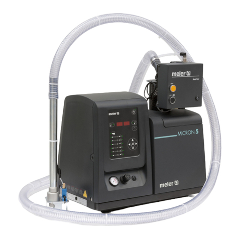
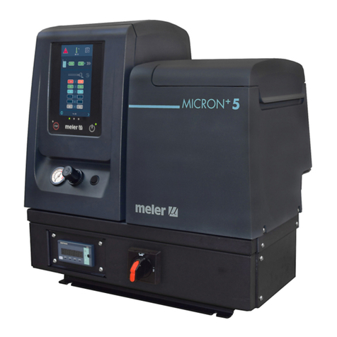
Meler Micron+ Series User manual

APPENDIX
EXTERNAL
DISPLAY
MICRON+
SERIES
INSTRUCTIONS
MANUAL
MA-5180-GBR 091019
GLUING SOLUTIONS

Published by:
Focke Meler Gluing Solutions, S. A.
P.I. Los Agustinos, calle G, nave D-43
E - 31160 Orkoien Navarra (España)
Tel.: + 34 948 351 110
Fax: + 34 948 351 130
e-mail: info@meler.eu
www.meler.eu
A Focke Group Company
Edition October 2019
© Copyright by Focke Meler
All rights reserved. Its reproduction, diffusion or use by electronic or other
means of all or any part of this document without the express authorization of
its owner is strictly prohibited.
The specifications and information contained in this manual may be modified
without prior notice.
This manual is a translation of the original that was written by Focke Meler
Gluing Solutions, S. A. in spanish language. If there is any discrepancy between
the different versions of this manual, the original written in the spanish
language shall prevail. Focke Meler Gluing Solutions, S. A. shall not be liable
in any way for any damages and/or losses that may be directly or indirectly
derived from discrepancies between the original version of the manual and this
translation.

TABLE OF CONTENTS MA-5180-GBR MICRON+APENDIX EXTERNAL DISPLAY
TABLE OF CONTENTS
1. SAFETY GUIDELINES 1-1
General 1-1
Symbols 1-1
Mechanical components 1-2
Electrical components 1-2
Hydraulic components 1-2
Pneumatic components 1-2
Thermal components 1-3
Materials 1-3
Noise emission declaration 1-3
Intended use 1-4
Limited use 1-4
2. INTRODUCCTION 2-1
Description 2-2
Modes of operation 2-2
Hot-melt melter/applicator identification 2-2
Main components of the equipment 2-3
Control panel components 2-4
Optional equipment 2-5
Controller bracket 2-5
3. INSTALLATION 3-1
Introduction 3-1
Installation requirements 3-1
Electrical Consumption 3-2
Compressed air 3-2
Mounting the equipment 3-2

FOCKE MELER GLUING SOLUTIONS TABLE OF CONTENTS
Other factors 3-3
Unpacking 3-3
Contents 3-3
Electrical power connection 3-4
Connection of the external display to the melter. 3-4
Parameter Programming 3-5
Pneumatic connection 3-5
4. TECHNICAL CHARACTERISTICS 4-1
Dimensions 4-1
5. ELECTRICAL DRAWINGS 5-1
6. SPARE PARTS LIST 6-1
A. ELECTRONIC ASSEMBLY 6-2
EC DECLARATION OF CONFORMITY 7-1

SEGURIDAD
1-1
MA-5180-GBR MICRON+APENDIX EXTERNAL DISPLAY
1. SAFETY GUIDELINES
General
The information contained in this section applies not only to everyday
equipment operation, but also to any procedure carried out on it, whether for
preventive maintenance or in the case of repairs and the replacement of worn
out parts.
It is very important to observe the safety warnings in this manual at all times.
Failure to do so may result in personal injury and/or damage to the equipment
or the rest of the installation.
Before beginning work on the equipment, read this manual carefully, and in
case of any doubt, contact our Technical Service Center. We are available for
any clarification that you might need.
Keep manuals in perfect condition and within reach of personnel that use the
equipment and perform maintenance on it.
Also provide necessary safety material: appropriate clothing, footwear, gloves
and safety glasses.
In all cases, observe local regulations regarding risk prevention and safety.
Symbols
The symbols used on both the melter/applicator equipment and in this manual
always represent the type of risk we are exposed to. Failure to abide by a
warning signal may result in personal injury and/or damage to the equipment
or the rest of the installation.
Warning: Risk of electrical shock. Carelessness may produce injury or death.
Warning: Hot zone with high temperatures. Risk of burns. Use thermal
protective equipment.
Warning: System under pressure. Risk of burns or particle projection. Use
thermal protective equipment and glasses.
Warning: Important information for the correct use of the system. May include
one or several of the previous hazards, and therefore must be kept in mind to
avoid damage and injury.
Warning: Dangerous area. Risk of entrapment. Carelessness may produce
injury or death.

FOCKE MELER GLUING SOLUTIONS
1-2
SEGURIDAD
Mechanical components
The hot-melt installation, which is installed to this device, requires moving
parts that can cause damage. Use the equipment correctly, and do not remove
the safety guards while the equipment is in operation; prevent the risk of
possible entrapment due to moving mechanical parts.
Do not use the equipment if the safety devices are not in place or appear to be
inadequately installed.
For maintenance or repair operations, stop the movement of moveable parts
by turning off the main switch.
The device has no moving mechanical parts, so it does not pose risks to
consider in this section.
Electrical components
The system works with single-phase or three-phase current of a certain
power. Never handle the equipment with the power connected, as this may
result in powerful electrical shocks.
The installation must be correctly grounded.
The installation’s power cable conductors must match the required electric
current and voltage.
Periodically inspect the cables to check for crushing, wear and tear, as well as
to prevent tripping and falls as a result of their placement.
Although the system meets EMC requirements, it is inadvisable to use
devices that transmit high levels of radiation, i.e., mobile phones or soldering
equipment in their vecinity.
Hydraulic components
As this is a pressurized system, precautions related to this type of equipment
must be observed.
Before each operation, always make sure that the adhesive circuit is
completely free of pressure. There is a high risk of hot particle projection,
along with the corresponding danger of burns.
Use caution with the residual pressure that may remain in the hoses when the
adhesive cools. When reheated, there is a risk of hot particle projection if the
outputs are left open.
Pneumatic components
Some equipment uses compressed air to 6 bar pressure. Before any
manipulation, please ensure that the circuit has lost fully air pressure. The
risk of projection of particles at high speed can cause injury to a certain
severity.
Extreme precautions with the residual pressure that could be contained in the
circuit, before disconnecting any pneumatic feeding tube.

SEGURIDAD
1-3
MA-5180-GBR MICRON+APENDIX EXTERNAL DISPLAY
Thermal components
The entire system works with temperatures that can exceed 200°C (392°F).
The equipment must be operated using adequate protection (clothing,
footwear, gloves and protective glasses) that completely cover exposed parts
of the body.
Keep in mind that, due to the high temperatures reached, the heat does not
dissipate immediately, even when the power (in this case, electric) source is
disconnected. Therefore, use caution, even with the adhesive itself. It may
remain very hot, even in a solid state.
In case of burns:
1. If the burn is the result of contact with melted adhesive, do not try to
remove the adhesive material from the skin. Do not try to remove it once
it has solidified either.
2. Cool the affected area down immediately with lots of cold and clean water.
3. Seek medical attention as soon as possible either from the company’s
medical service or the nearest hospital. Provide the medical staff with the
Safety Information Sheet of the adhesive.
Materials
Meler systems are designed for use with hot-melt adhesives. They should
not be used with any other type of material, and especially not with solvents,
which may cause personal injury or damage to internal system components.
Some units are specifically designed to use polyurethane reactive (PUR) hot-
melt adhesives. Using PUR on a unit that is not prepared for that purpose may
cause severe damage to the unit.
When using adhesive, follow the corresponding guidelines found in the
Technical and Safety Sheets provided by the manufacturer. Pay special
attention to the advised work temperatures in order to prevent adhesive
burning and degradation.
Ventilate the work area adequately in order to remove the vapors produced.
Avoid the prolonged inhalation of these vapors.
Always use original Meler components and replacement parts, which
guarantee the correct system operation and service.
Noise emission declaration
The A-weighted emission sound pressure level (LpA) of the unit in operation
does not exceed 70 dB(A) under any circumstances.
The maximum C-weighted sound pressure level (LpCpeak) and the A-weighted
sound power level (LWA) do not exceed values worthy of mention and thus do
not represent a specific risk that must be taken into account.

FOCKE MELER GLUING SOLUTIONS
1-4
SEGURIDAD
Intended use
The equipment are designed to be used in the following conditions:
• Hot-melt adhesive fusion and pumping at temperatures up to 200 °C
(392 ºF). Consult with Meler technical service to operate with higher
working temperatures.
• Use of equipment with Meler accessories.
• Installation of equipment according to the security regulations
currently in force and the instructions provided in this manual
(anchoring, electrical connection, hydraulic connection, etc).
• Use of equipment in non-explosive, non-chemically aggressive
environments.
• Use of equipment following the safety instructions indicated in this
manual, as well as on the labels accompanying the equipment, using
adequate means of protection during each mode of operation.
Limited use
The equipment should never be used under the following conditions:
• Use with reactive polyurethane or any other material that might cause
safety or health risks when heated.
• Use of equipment in environments where cleaning is necessary using
water jets.
• Use of equipment to heat or melt food products.
• In potentially explosive atmospheres, aggressive chemical
environments or outdoors.
• Use or operation without adequate safety protection.
• If the person in question does not have the necessary training to use
the unit or to apply all of the necessary safety measures.
Note: Do not modify the equipment or use components that were not supplied
by Meler. For any modification of a component of the equipment or part of the
installation, you must firstly consult the After-Sales Service

INTRODUCCTION
2-1
MA-5180-GBR MICRON+APENDIX EXTERNAL DISPLAY
External HMI
2. INTRODUCCTION
In this manual you will find information about the installation, use and
maintenance of the hot-melt adhesive melter/applicator in meler’s MICRON+
series.
The ‘MICRON+’ series includes the 5, 10, 20 and 35 liter range of hot-melt
adhesive melters/applicators.
Most of the photographs and illustrations that appear in this manual refer
to the 5-liter ‘MICRON+’ melter/applicator. This model has been used as
a reference for writing this manual as its main characteristics, with the
exception of the tank capacity and the connection outputs are the same as
those in the rest of the ‘MICRON+’ series..
This model consists of an external control unit from which you can operate the
equipment.

FOCKE MELER GLUING SOLUTIONS
2-2
INTRODUCCTION
Description
The ‘MICRON+’ are designed for use with ‘meler’ hoses and applicators in hot-
melt adhesive applications. Their different variations – line, coating or swirl-
spray – cover a wide range of applications, being very versatile in all markets
where they are used.
Modes of operation
The ‘MICRON+’ series hot-melt melters/applicators may be used in all of the
following modes:
Work mode_The hot-melt melter/applicator keeps materials hot at the
pre-selected temperature indicated on the display. The pump is kept
activated, waiting for the consumption command when one or more
application applicators are activated.
Standby mode_The hot-melt melter/applicator remains in a resting
state, with the materials kept at (programmable) temperature values
below the pre-selected value. The pump remains deactivated.
Alarm mode_The hot-melt melter/applicator detects a malfunction
and warns the operator of this event. The pump remains deactivated.
OFF mode_The hot-melt melter/applicator remains off, without
heating the materials and with the pump deactivated. The electrical
and pneumatic supply remains activated between the network and the
system, however.
Hot-melt melter/applicator identification
When placing orders for replacement parts or requesting help from our
service center, you should know the model and reference number of your hot

INTRODUCCTION
2-3
MA-5180-GBR MICRON+APENDIX EXTERNAL DISPLAY
Main components of the equipment
1. Front control card
2. Outdoor housing
3. Main switch
4. Connectors to external control device
5. External control board
6. Connection input
7. Characteristics plate
1
6
23
3
5
45

FOCKE MELER GLUING SOLUTIONS
2-4
INTRODUCCTION
Control panel components
1. Touch screen.
2. Status central leds (GREEN, YELOW, RED).
3. RED led ‘pumping OFF’.
4. STOP RED Button ‘Start/Stop Pump’.
5. Touch screen ON/OFF button.
6. GREEN led ‘power ON’.
1
2
3
4 5
6

INTRODUCCTION
2-5
MA-5180-GBR MICRON+APENDIX EXTERNAL DISPLAY
Optional equipment
To increase the functionality of the melter machines, the following optional
elements can be incorporated:
• Low level of melted adhesive detection system. This can be fitted to
all the machines in float switch or capacitive sensor options.
• Adaptation plate for previous models. For adapting ST machines, the
previous 4, 8 and 16l machines and MICRON range 5, 10 20 and 35
liters.
• 4 casters: Only for 20 and 35l machines
Controller bracket
This programmer unit, which is external to the Micron equipment, can be
installed on different brackets.
The bracket must be requested separately and comes in two types: a vertical
bracket (standing) (1) and an articulated wall bracket (2)
1. Vertical bracket 2. Articulated wall bracket

FOCKE MELER GLUING SOLUTIONS
2-6
INTRODUCCTION
This page is intentionally left blank.

INSTALLATION
3-1
MA-5180-GBR MICRON+APENDIX EXTERNAL DISPLAY
3. INSTALLATION
Warning: The melters/applicators are equipment with current technology and
with certain foreseeable risks. Therefore, only allow qualified personnel with
sufficient training and experience to use, install or repair this equipment.
Introduction
The ‘MICRON+’ series melters/applicators are delivered with all the materials
necessary for their installation. However, some components must be provided
by the user himself, according to the location and connections in each
particular installation:
• Anchoring screws for the melter/applicator equipment
• Power cord and plug for electrical power
• Pneumatic pipe and connection to the compressed air system
• Multicore cable for external electrical control
• Optionally, a gas ventilation system
• Another option is fixing systems from the external operator (brackets)
Installation requirements
Before installing ‘MICRON+’ series melter/applicator equipment, we must
make sure that the space assigned to it permits installing, connecting and
using the entire system. Similarly, we must check to see that the electrical
and pneumatic supplies meet the necessary requirements of the melter/
applicator equipment being installed.
Bear in mind that the equipment consists of a controller that is external to
this one, which allows it to be adjusted from different positions and distances..
This device can be installed according to the customer’s wishes.
It can be installed from a fixed or mobile position. Vertical bracket or
articulated wall bracket (the brackets must be requested separately).

FOCKE MELER GLUING SOLUTIONS INSTALLATION
3-2
Electrical Consumption
In order to install a ‘MICRON+’ series melter/applicator, we should take
into consideration the total consumption of the installation, including the
consumption of the installed hoses and applicators.
Before connecting, make sure that the voltage that is being connected to
the melter/applicator is the correct one appearing on the equipment’s
characteristics plate.
Connect the machine and check to see if it is well grounded.
Warning: Risk of electrocution. Even when the equipment is turned off,
voltage remains in the intake terminals, which may be dangerous during
internal equipment manipulations.
Install a power switch for disconnecting the melter/applicator equipment from
the electrical network. It must be protected against overload and short circuits
by circuit breaker and install appropriate personal protection leads to mass by
differential switch.
Consumption figures, according to melter/applicator and output configuration,
are included in the table in the section ‘Electrical power connection’.
Compressed air
To install ‘MICRON+’ series melters/applicators, it is necessary to have a dry,
non-lubricated compressed air system with a maximum pressure of 6 bar.
The applicator’s internal pneumatic equipment is able to work with a
minimum of 0.5 bar, however, pressure lower than this will cause intermittent
operational anomalies.
The air consumption is according to the number of stroke made by the pump
cylinder, which in turn depends on the adhesive consumption during the
application. It is therefore necessary to estimate this consumption in all cases.
Generally speaking, we can provide as a maximum consumption value 40-50
l/min for a pressure of 6 bar at maximum pump speed.
Mounting the equipment
For mounting the ‘MICRON+’ series set the base in the desired location using
the indicated holes M8 screws.
The ‘MICRON+’ series equipments have an optional adaptation plate for fixing
‘MICRON+’ 5, 10, 20, 35 and previous ‘MICRON’ range 4, 8, 16, 32 and ST
machines. To mount the base plate, place it on the machine bench and adjust
its position. Mark and drill the four holes for the base plate’s M8 fastening
screws. The holes may be threaded or non-threaded, depending on the bench
to which they are being attached.
Warning: Make sure that the bench where the base plate is fastened is level,
free from vibrations and is able to support the weight of the equipment in
addition to the full tank load. Once the base plate is fastened in place on the
bench, the melter/applicator should be mounted on top of it.

INSTALLATION
3-3
MA-5180-GBR MICRON+APENDIX EXTERNAL DISPLAY
To fix the external device, it is possible to acquire two bracket models that
allow it to be adjusted according to the operator’s needs.
Two types of bracket, a model that allows the controller to be fitted vertically
with a standing bracket. Another wall bracket that allows the angle and dis-
tance to be adjusted via an articulated system.
Other factors
While installing ‘MICRON+’ series melters/applicators, other practical
considerations should be kept in mind:
• Keep the load opening accessible for comfortable melter/applicator
filling.
• Position the melter/applicator equipment in such a way that you can
easily see the front panel display where temperatures and possible
alarm signals are shown.
• As much as possible, try to avoid unnecessarily long hoses that result
in elevated electrical energy consumption levels and pressure drops.
• Do not install the melter/applicator equipment beside powerful heat or
cooling sources that may have distortional effects upon its operation.
• Avoid melter/applicator vibrations.
• Make sure that the melter/applicator maintenance areas (filter, purging
valve, tank interior, etc.) are easily accessible.
Unpacking
Before proceeding with the installation of the melter/applicator, it should be
removed from its location on a pallet and examined in order to detect any
possible breakage or deterioration. Communicate any defect, even to the outer
packing materials, to your ‘meler’ Representative or to the Main Office.
Contents
The ‘MICRON+’ series packing materials may contain accessories that form
part of the same order. If this is not the case, the following are the standard
components that accompany the melter/applicator:
• Instruction manual.
• Guarantee card.
• Hose couplings.
• Set connectors for Inputs / Outputs.
• Bracket for external programmer

FOCKE MELER GLUING SOLUTIONS INSTALACIÓN
Electrical power connection
‘MICRON+’ series melters/applicators are designed to be connected to the
electrical power supply in three possible ways, depending on the power of
different elements connected:
• 1-phase 230 VAC with neutral
• 3-phases 400 VAC with neutral
• 3-phases 240 VAC without neutral
A good ground connection is required in all cases.
Consumption figures, according to melter/applicator and output configuration,
are included in the table. Due to high power connected ‘meler’ recommends
3-phases 400 VAC with neutral connection.
Warning: Risk of electrical shock. Carelessness may cause injury or death.
Open the electric cabinet door as far as possible. Thread the power cord (max.
Ø18mm) through the electrical wall bushing (P) and fasten it to the inside
anchor, making sure that the cord reaches the power card connector at the
position where it will be installed.
Connect each wire in the power cord to its corresponding place on the power
intake connector on the power card.
Consumption values concerning each equipment can be found in the
characteristics plate.
Connection of the external display to the melter.
The equipment is factory installed. Connect the hose to the back of the equip-
ment.
P
12

INSTALACIÓN
3-5
MA-5180-ESP ANEXO PANTALLA EXTERIOR MICRON+
Parameter Programming
Once the melter/applicator and its components are installed, you will need to
program the operational parameters appropriate for the specific application
that will be performed.
Among the various parameters, it is necessary to program the set point
temperature values for each component connected and the value for
overheating warnings. There are two other parameters (weekly start-up and
shut-down programming and the standby temperature value) left to program
in advanced systems, although the factory default values are perfectly valid for
operational purposes.
Chapter “4. MELTER OPERATION” details the operating modes of the machine
and its configuration (MA-5162)
Pneumatic connection
Before connecting the pneumatic power to the melter/applicator, make
sure the pressure regulator is completely closed. To do this, turn the
regulator located on the front of the equipment next to the pressure gauge
counterclockwise as far as it will go.
Connect the plant air supply (max. 6 bar) to the melter/applicator intake using
flexible tubing with an outside diameter of 8 mm. The equipment is provided
with a quick coupling for this purpose.
Activate the air supply to pass and turn the pressure regulator clockwise.
Adjusting to 1 bar of pressure is enough for checking the pump operation.
The pump will not operate and the pressure gauge will show 0 bar until the
melter/applicator and the hoses-applicators connected to it reach the correct
temperature.
Once the pump operation has been checked, you may adjust the pressure to
the operational value you wish.
In the pressure gauge can be found pneumatic and hydraulic pressure values,
the relation between both are 1:13,6.

FOCKE MELER GLUING SOLUTIONS INSTALLATION
3-6
This page is intentionally left blank.
Other manuals for Micron+ Series
2
This manual suits for next models
1
Table of contents
Other Meler Laboratory Equipment manuals
Popular Laboratory Equipment manuals by other brands

Cantium Scientific
Cantium Scientific P0059 operating manual

Qiagen
Qiagen EZ1 Advanced XL quick start

3M
3M Steri-Vac GSX Series Operator's manual

Thermo Scientific
Thermo Scientific Variomag MAXI DIRECT operating manual

DENTSPLY
DENTSPLY thermaprep plus instruction manual

Klein Tools
Klein Tools TI222 instruction manual

VWR
VWR avantor Homogeniser M instruction manual

EGi
EGi Geoscan user manual

Advanced Instruments
Advanced Instruments ARTEL PCS quick start guide

Hartridge
Hartridge HK853 user manual

Bradley
Bradley S19294HB Installation

Thermo Scientific
Thermo Scientific Thermo Scientific Sorvall Legend Micro... instruction manual