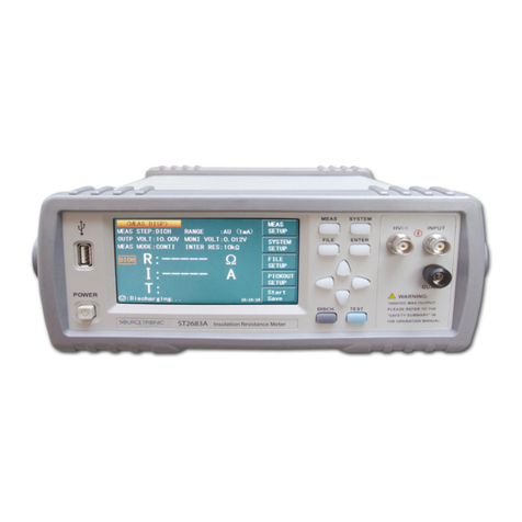
Sourcetronic ST2684A User manual

SOURCETRONIC −Qualitäts-Elektronik für Service, Labor und Produktion
Insulation resistance meter ST2684A
Manual

ST2684/A Operation Manual Ver1.01
Manual Printing History
The manual’s printing date indicates its current edition. The printing date changes when a new edition is printed.
(Minor corrections and updates that are incorporated at reprint do not cause the date to change.) The manual
edition changes when extensive technical changes are incorporated.
March 2011…………………………………….. First edition
First Edition
March 2011
Notice: Descriptions contained in this manual may not cover all information about this instrument.
Introductions to the improvements of the instrument in performance, function, internal structure, outer
appearance, accessories, packing material, etc. are subject to change without notice. If you find any
inconformity of this manual with our instruments, please contact us for further consultation by the address listed
on the cover.

ST2684/A Operation Manual Ver1.01
Safety Cautions:
Ground
The instrument is class I. Make sure that there is a ground
connection in the mains outlet. Failure to do this may cause
personnel injury because of the existence of static or induced
electricity on the instrument cover.
Shock Hazard
At the phases of operating, testing and maintaining the instrument,
electric shock must be avoided. Do not attempt to remove the
instrument cover, replace the fuse or maintain the instrument
unless another person, capable of rendering first aid and
resuscitation, is present and the power plug is unplugged. Even
under this condition, dangerous voltages may also exist on
capacitors. For this reason, all servicing operations mentioned
above must be taken after discharging the circuit and be
performed by professionals.
Shock Damage
For the presence of high voltage in test terminals, it is important to
connect and disconnect the DUT correctly in all test phases. Failure
to do this may cause damage to the instrument and injury to
personnel.
User should be liable for all fees to repair the damages that are
caused by abnormal operations.
See 1.2.4.
Power Supply
Be sure to use a power supply in accordance with the specifications
in this manual. Failure to comply with these specifications may
result in damage to the instrument.
Keep away from
dust and explo-
sive atmosphere
Do not operate the instrument in the presence of explosive and
flammable gases or dust. Operation of any electrical instrument in
such an environment constitutes a definite safety hazard.
Other cautions
Do not apply any voltage or current source in the test terminals.
Note
Important supplement or warning for the stated content.

ST2684/A Operation Manual Contents
- i -
Contents
Chapter 1 Introduction....................................................................................................................1
1.1 Introduction .................................................................................................................................1
1.2 Service conditions........................................................................................................................1
1.2.1 Power ..........................................................................................................................1
1.2.2 Enviromental temperature and humidity...........................................................................1
1.2.3 Warm-up............................................................................................................................1
1.2.4 Cautions
!
.......................................................................................................................2
1.3 Dimension and weight.................................................................................................................2
1.4 Safety...........................................................................................................................................2
1.4.1 Insulation resistance..........................................................................................................2
1.4.2 Insulation intensity............................................................................................................2
1.4.3 Leakage current.................................................................................................................2
1.5 Electromagnetic compatibility.....................................................................................................3
Chapter 2 Introduction to Front and Rear Panels ...........................................................................4
2.1 Instroduction to front panel .........................................................................................................4
2.2 Introduction to rear panel ............................................................................................................6
2.3 Display zone................................................................................................................................7
2.4 Main menu keys and their corresponding display pages.............................................................8
2.4.1 DISP..................................................................................................................................8
2.4.2 SETUP ..............................................................................................................................8
2.4.3 SYSTEM...........................................................................................................................8
2.5 Basic operations...........................................................................................................................8
2.6 Start-up ........................................................................................................................................9
Chapter 3 [DISP] .............................................................................................................................10
3.1 <MEASURE DISP>..................................................................................................................10
3.1.1 HV1.................................................................................................................................11
3.1.2 I1_MAX..........................................................................................................................11
3.1.3 HV2.................................................................................................................................12
3.1.4 I2_MAX..........................................................................................................................13
3.1.5 SPEED ............................................................................................................................13
3.1.6 Average (AVG)................................................................................................................14
3.1.7 RANGE...........................................................................................................................14
3.1.8 Rin_L ..............................................................................................................................14
3.1.9 TRIG ...............................................................................................................................15
3.1.10 MODE...........................................................................................................................16
3.1.11 FILE..............................................................................................................................16
3.2 BIN DISP...................................................................................................................................16
3.2.1 FILE................................................................................................................................17
3.3 BARGRAPH DISP....................................................................................................................17
3.3.1 BAR SCALE...................................................................................................................18
3.3.2 FILE................................................................................................................................19
3.4 SEQUENCE DISP.....................................................................................................................19
3.4.1 FILE................................................................................................................................19
3.5 XY GRAPH...............................................................................................................................20
3.6 SCAN DISP...............................................................................................................................20
3.6.1 FILE................................................................................................................................21

ST2684/A Operation Manual Contents
- ii -
Chapter 4 [SETUP]..........................................................................................................................22
4.1 <MEASURE SETUP> ..............................................................................................................22
4.1.1 RESULT..........................................................................................................................23
4.1.2 HV2 TRACK ..................................................................................................................23
4.1.3 DISCHARGE..................................................................................................................24
4.1.4 MEASURE DELAY .......................................................................................................24
4.1.5 CHARGE TIME .............................................................................................................25
4.1.6 HUM REJECT................................................................................................................26
4.1.7 CONTACT CHECK........................................................................................................26
4.2 LIMIT SETUP...........................................................................................................................26
4.2.1 COMP: ON/OFF.............................................................................................................27
4.2.2 Limit mode of compare function ....................................................................................28
4.2.3 Setting nominal value......................................................................................................29
4.2.4 High and low limits.........................................................................................................29
4.2.5 File manage.....................................................................................................................30
4.2.6 TOOLS............................................................................................................................30
4.3 BARGRAPH SETUP................................................................................................................30
4.3.1 BAR SCALE...................................................................................................................31
4.3.2 FILE................................................................................................................................32
4.4 SEQUENCE SETUP.................................................................................................................32
4.4.1 SELECTED SEQ............................................................................................................33
4.4.2 DEFAULT SEQ...............................................................................................................33
4.4.3 USER SEQ......................................................................................................................34
4.4.4 FILE................................................................................................................................34
4.5 SEQ. CONTENT.......................................................................................................................35
4.5.1 Basic test theory and specifictaions................................................................................35
4.5.2 ITEM...............................................................................................................................37
4.5.3 NO...................................................................................................................................40
4.5.4 HV...................................................................................................................................40
4.5.5 RANG.............................................................................................................................41
4.5.6 AVG.................................................................................................................................41
4.5.7 LOW, HIGH....................................................................................................................42
4.5.8 TIME...............................................................................................................................43
4.5.9 FILE................................................................................................................................43
4.6 XY GRAPH SETUP..................................................................................................................43
4.6.1 X-SCALE........................................................................................................................44
4.6.2 SET TIME.......................................................................................................................44
4.6.3 Y-SCALE ........................................................................................................................45
4.6.4 CUR SCOPE...................................................................................................................45
4.6.10 FILE..............................................................................................................................45
4.7 SCAN SETUP ...........................................................................................................................46
4.7.1 SELECTED SEQ............................................................................................................46
4.7.2 SCAN START NUM.......................................................................................................47
4.7.3 SCAN END NUM ..........................................................................................................47
4.7.4 SCAN RESULT..............................................................................................................47
4.7.5 SCAN CONNECT..........................................................................................................48
4.7.6 FILE................................................................................................................................48
4.8 USER ADJUST .........................................................................................................................48
4.8.1 OPEN CORR:ON/OFF................................................................................................49
4.8.2 OPEN CORR..................................................................................................................49
4.8.3 LOAD CORR: ON/ OFF ................................................................................................50
4.8.4 REFERENCE..................................................................................................................50
4.8.5 FILE................................................................................................................................50
Chapter 5 [SYSTEM]......................................................................................................................51

ST2684/A Operation Manual Contents
- iii -
5.1 <SYSTEM SETUP>..................................................................................................................51
5.1.1 L CD contrast..................................................................................................................51
5.1.2 LCD Style .......................................................................................................................51
5.1.3 Pass beeper......................................................................................................................52
5.1.4 Fail beeper.......................................................................................................................52
5.1.5 Language.........................................................................................................................53
5.1.6 Handler............................................................................................................................53
5.1.7 Password.........................................................................................................................53
5.1.8 Bus mode ........................................................................................................................54
5.1.9 GPIB address ..................................................................................................................54
5.1.10 Baud rate.......................................................................................................................54
5.1.11 Time ..............................................................................................................................55
5.2 <FILE MANAGE>....................................................................................................................55
5.2.1 *.STA ..............................................................................................................................56
5.2.2 Operational steps for file manage ...................................................................................58
Chapter 6 Measurement Procedures and Examples.........................................................................61
6.1 Safety Precautions .....................................................................................................................61
6.2 Installation.................................................................................................................................61
6.3 Example for automatic testing...................................................................................................61
6.4 Insulation Testing of Capacitors................................................................................................63
6.5 Charge Resistors for Automated IR Testing ..............................................................................65
6.6 Insulation resistance measurement............................................................................................69
6.7 Examples for sequence test........................................................................................................72
Chapter 7 Test Performance.............................................................................................................73
7.1 I.R./L.C. TEST ..........................................................................................................................73
7.1.1 Measurement parameters ................................................................................................73
7.1.2 General specifications.....................................................................................................73
7.1.3 Specifications..................................................................................................................74
7.2 Safety summary.........................................................................................................................75
7.2.1 Insulation resistance (IR)................................................................................................75
7.2.2 Insulation intension.........................................................................................................75
7.2.3 Leakage current...............................................................................................................75
7.2.4 The EMC requirement.....................................................................................................75
Chapter 8 Remote Control...............................................................................................................76
8.1 RS232C interface operation....................................................................................................76
8.1.1 RS232C connection.........................................................................................................76
8.1.2 Communicating with PC.................................................................................................77
8.2 GPIB interface operation...........................................................................................................78
8.2.1 GPIB bus.........................................................................................................................78
8.2.2 GPIB interface capability................................................................................................80
8.2.3 GPIB addressing .............................................................................................................80
8.2.4 GPIB bus commands.......................................................................................................80
8.2.5 SCPI(Standard Commands for Programmable Instruments).....................................81
8.3 USB remote control system.......................................................................................................81
8.3.1 System configuration ......................................................................................................81
8.3.2 Install drive .....................................................................................................................81
8.4 USBCDC virtual serial port....................................................................................................82
8.4.1 System configuration ......................................................................................................82

ST2684/A Operation Manual Contents
- iv -
8.4.2 Install drive .....................................................................................................................82
Chapter 9 Command Reference.......................................................................................................83
9.1 GPIB common commands for ST2684......................................................................................83
9.2 Command structure............................................................................................................85
9.3 Command syntax.......................................................................................................................86
9.4 Input format...............................................................................................................................86
9.5 SCPI commands ........................................................................................................................87
9.5.1 System commands...........................................................................................................87
9.5.2 DISPlay subsystem commands.......................................................................................87
9.5.3 MsetSETup subsystem commands..................................................................................89
9.5.4 TRIGger subsystem command........................................................................................92
9.5.5 HTOUtput subsystem commands ...................................................................................93
9.5.6 HUMReject subsystem commands.................................................................................93
9.5.7 CCHEck subsystem commands ......................................................................................93
9.5.8 MESTb subsystem commands........................................................................................94
9.5.9 MEER subsystem commands..........................................................................................94
9.5.10 LIMIt subsystem commands.........................................................................................94
9.5.11 Mass MEMory subsystem commands...........................................................................96
9.5.12 UserADJust subsystem commands...............................................................................96
9.5.13 XYGRaph subsystem commands..................................................................................98
9.5.14 SEQSetup subsystem commands..................................................................................99
9.5.15 SeqCONt subsystem commands.................................................................................102
9.5.16 SCANSetup subsystem commands.............................................................................103
9.5.17 BARSetup subsystem commands ...............................................................................104
9.5.18 FETCh? subsystem commands...................................................................................105
Chapter 10 Handler Interface.........................................................................................................106
10.1 Pins of HANDLER interface.................................................................................................106
10.2 Electrical characteristics........................................................................................................107
10.3 BIN signals............................................................................................................................108
10.3.1 BIN signals in the test display page............................................................................108
10.3.2 BIN signals in the sequence display page...................................................................109
10.4 Examples for HANDLER input/ output ................................................................................109
Chapter 11 Package Contents and Warranty..................................................................................110
11.1 Package contents....................................................................................................................110
11.2 Warranty.................................................................................................................................110

ST2684/A Operation Manual Chapter 1 Introduction
1
Chapter 1 Introduction
Thank you for your purchase and use of our products! Before using the instrument, please locate the items listed on
the package list or in this manual to ensure nothing is missing. If in the case that any item is missing, please contact
us without delay.
1.1 Introduction
ST2684/ST2684A is an insulation resistance meter that is high in speed and accuracy. It bears the advantages of LCD
display, user-friendly menu, simple operations and great conveniences. Interfaces, such as USB, HANDLER
RS232C, scanning and IEEE488 (optional) are available, making it possible for the instrument to be used in an
automatic sorting system and PC remote control operations.
Basic specification:
Test voltage range: ST2684: 10V to 505V
ST2684A: 10V to 1005V
Charging current range: ST2684: 2 mA, 25 mA, 200mA selectable
ST2684A: 2 mA, 25 mA, 100mA selectable
Resistance measurement range: ST2684: 10kΩto 50TΩ
ST2684A: 10kΩto 100TΩ
Measurement accuracy: ±2%(<1TΩ)
Contact check: Check the contact of capacitive materials such as capacitors, cables being good or bad.
Power failure data-store: This function is supported by a lithium battery with a 2-year battery life. If it exceeds 2
years, this function may be disabled.
IEEE-488 interface (optional): this interface provides convenience for instrument and computer or other
instruments to make an automatical test system.
The command of RS-232 and IEEE-488 interface is written by SCPI format.
HANDLER interface: the instrument is synchronized with the machinery processing instrument in automatical
test system, and the result is output to the machinery processing instrument.
1.2 Service conditions
1.2.1 Power
Main voltage: 220V (1±10%)
Frequency: 50Hz/60Hz (1±5%)
Consumption: <120VA
1.2.2 Environmental temperature and humidity
Normal working temperature: 0C~40C, humidity: < 90%RH
Reference working temperature: 20C±8C, humidity: < 80%RH
Transportation temperature: 0C~55C, humidity: 93%RH
1.2.3 Warm-up
Warm up time: ≥30 min.

ST2684/A Operation Manual Chapter 1 Introduction
2
1.2.4 Cautions
!
(1)Please do not operate the instrument in the places where is vibrative, dusty, under direct sunlight, or where
there is corrosive air.
(2)Please store the instrument in an airy room where temperature is between 5℃and 40℃, relative humidity is
less than 85% RH and no corrosive impurities and direct sunlight exists. If the instrument will not be put in use for a
time, please have it properly packed with its original box or a similar box for storing.
(3)Although the instrument has been specially designed for reducing the noise caused by AC power, a place
with low noise is still recommended. If this cannot be arranged, please make sure to use power filter for the
instrument.
(4)ST2684/2684Ahas the cooling fan on the rear panel and cooling holes on both sides. High temperature inside
will decrease the measurement accuracy, so sufficient space must be kept around the instrument to avoid obstructing
the air flow of the cooling fans.
(5)Do not frequently turn on or off the instrument, doing so will lead to the loss of the calibrated data and the
data saved by users.
(6)Correct test methods:
DO NOT connect a capacitor to the instrument when it is outputting a high voltage (>50V). Abnormal
operations may cause damages to the instrument; in this case user should be liable for all maintenance fees.
1.3 Dimension and weight
Dimension (W*H*D): 350mm*120mm*400mm
Weight: approx. 7kg
1.4 Safety
The instrument is in the class I.
1.4.1 Insulation resistance
Under the reference working condition, the insulation resistance between power terminal and shell is no less than
50MΩ.
Under transportation condition, the insulation resistance between power terminal and shell is no less than 2MΩ.
1.4.2 Insulation intensity
Under the reference working condition, the power terminal and shell can withstand a rated AC voltage of 1.5kV,
50Hz for 1Min, and no breakdown and arc phenomenon exists.
1.4.3 Leakage current
Leakage current is no larger than 3.5mA.

ST2684/A Operation Manual Chapter 1 Introduction
3
1.5 Electromagnetic compatibility
Power instantaneous sensitivity is based on GB6833.4.
Transmission sensitivity is base on GB6833.6.
Radiated interference is based on GB6833.10.

ST2684/A Operation Manual Chapter 3 [DISP]
4
Chapter 2 Introduction to Front and Rear
Panels
2.1 Introduction to front panel
Figure 2-1 Front Panel
Introduction to the front panel is as follows:
Table 2-1 Introduction to the front panel
No.
Name
Introduction
1
Brand and model
ST2684 or ST2684A
Insulation Resistance Meter
2
LCD
320*240 dot-matrix LCD displaying all
measurement parameters, status, measurement
results, etc.
3
SOFTKEYs
The five keys have different functions in
different menus.
4
DISPLAY
Enter the measure display page.
5
SETUP
Enter the measure setup page.
6
CURSOR
Control the movement of cursor on the screen,
the selected parameter is displayed with
highlight.
7
SYSTEM
Enter the system setup page.
8
Number/ Letter
keyboard
Input the desired number or character (file
name).
9
BACKSPACE
Delete numbers or letters if desired.
10
ENTER
Confirm input numbers.
11
TEST
Trigger a test or start the test sequence when the

ST2684/A Operation Manual Chapter 3 [DISP]
5
instrument is set in manual trigger mode.
12
HV indicator()
The indicator lights up when the voltage across
the two test terminals is higher than 0.4V;
otherwise it is off.
13
PASS indicator
The indicator lights up when the limit setup
requirements are met; otherwise it is off.
14
FAIL
The indicator lights up when the limit setup
requirements are not met; otherwise it is off.
15
HV
Start or stop the high voltage test. Press this
button one time to start the high voltage test;
press it again to stop the high voltage test or the
test sequence.
16
GUARD
Connect with the DUT shielding layer in the
purpose of isolating external electromagnetic
interference and improving measurement
accuracy and stability.
17
INPUT
INPUT: current sampling terminal
18
HV1
HV1(-): negative voltage output terminal
Provide voltage output for testing.
19
POWER
Switch on or off 220V/110V.
In position of the push-button switch means the
power supply is on.
Out position of the push-button switch means
the power supply is off.
20
USB interface
Communicate with an USB device.
21
PRINT
Print the current displaying page into an USB
device.

ST2684/A Operation Manual Chapter 3 [DISP]
6
2.2 Introduction to rear panel
HANDLER SCANNER DEVICE RS-232C
GPIB
HV2 OUTPUT
RATING FUSE
T2AL
~T5AL
110V / 60Hz
~220V /50Hz
Figure 2-2 Rear Panel
Introduction to the rear panel is as follows:
Table 2-2 Introduction to the rear panel
No.
Name
Introduction
1
HV2 OUTPUT
HV2(-): negative voltage output terminal
Provide voltage output for charging.
2
GPIB interface
(optional)
Provide the universal parallel communication
interface for instrument and external device. All
parameter setup and command are set and
obtained by computer to realize the remote
control.
3
Fan window
Be used to dissipate heat and to maintain a normal
working temperature for the instrument.
4
3-cable power
socket
Choose and connect the 220V/50Hz or
110V/60HzAC power.
5
Fuse socket
Hold the power fuse. Toggle the voltage input
between 110V and 220V by changing the
direction of the inner core.
6
Ground
Connect with the instrument cover to protect or
shield the ground connection.
7
RS232C
Provide the universal serial communication
interface for instrument and external device. All
parameter setup and command are set and
obtained by computer to realize the remote
control.
8
DEVICE
PC can control ST2684 through the USB

ST2684/A Operation Manual Chapter 3 [DISP]
7
DEVICE interface.
9
SCANNER
The instrument can connect with a multi-channel
scanner through this interface to realize a
multi-channel test.
10
HANDLER
An automatic test system can be conveniently
constructed via this interface to fulfill automatic
tests. The instrument outputs bin compare result
signals and handshake signals, meanwhile a
“start-up” signal will also be sent to the
instrument via it.
11
Label plate
Record the date, model, manufacturer, etc.
2.3 Display zone
ST2684 adopts a 320×240 dot-matrix LCD. The display screen is divided into the following
zones, as shown in figure 2-3.
1) Main menu
Indicate the name of the currently displayed page.
2) File
When the cursor is moved to this zone, user can take operations of file manage, such as load, save and
delete.
3) Tool
Some functions not frequently used are listed in this setting zone.
4) Softkeys
This zone displays the function of each softkey in each menu. The five keys have different functions in
different menus.
5) Measurement result/ conditions
Indicate the measurement result and the current conditions.

ST2684/A Operation Manual Chapter 3 [DISP]
8
6) Prompt information
Indicate all prompt information and the user-input data.
2.4 Main menu keys and their corresponding display pages
2.4.1 DISP
Press this key to enter into MEASURE DISP. The following items will be displayed in this page (select
corresponding functions by softkeys, the same as below).
<MEAS DISP>
<BIN DISP>
<SEQ. DISP>
<BAR. DISP>
<XY GRAPH>
<SCAN DISP>
2.4.2 SETUP
Press this key to enter into MEASURE SETUP. The following items will be displayed in the page:
<MEAS. SETUP>
<LIMIT SETUP>
<BAR. SETUP>
<SEQ. SETUP>
<XY SETUP>
<SCAN SETUP>
<USER ADJUST>
2.4.3 SYSTEM
Press this key to enter into SYSTEM SETUP. Functions such as system setup and file list can be started in
this page. The following item will be displayed:
<SYSTEM SETUP>
2.5 Basic operations
Basic operations for ST2684 are as follows:
Press [DISP], [SETUP] or [SYSTEM] and select softkeys to enter into the desired page to display (see
figure 2-5).
Move the cursor to the desired zone to set by pressing [←], [↑], [→] or [↓]. The selected zone will be

ST2684/A Operation Manual Chapter 3 [DISP]
9
displayed with highlight.
Softkey functions corresponding to the currently selected zone will be displayed in the softkey zone.
User can choose the desired function by pressing a softkey. Numerical keys, [BACKSPACE] and
[ENTER] are used to input data.
Once a numerical key is pressed, unit softkeys that can be used will be displayed in the softkey zone.
You can press the unit softkey or [ENTER] to finish inputting. When [ENTER] is pressed to finish
inputting, the unit will be the default unit corresponding to the current parameter, such as S, V orA.
2.6 Start-up
Connect the instrument to a 3-wire power socket.
NOTE: The instrument must be operated at the voltage of 90 V to 130 V AC (60Hz) or 198 V to 260V
AC (50HZ).
Line wire (L), neutral wire (N) and earth ground (E) of the power socket should correspond to that of the
instrument power plug.
Turn on the instrument by pressing the power switch on the bottom left corner of the front panel. The
boot screen will be displayed.
Figure 2-4 shows the boot screen of ST2684 including our trade mark, instrument model (ST2684) and
the software version (Ver. 1.0.0):
If the password protection is enabled, you will be required to input your password. After inputting your
password, press [ENTER] to enter into the main menu page.
——————————————————————————————————————
Note: This series of products have enabled password protection and the default password is 2684. You
can reset the password by yourself. See the password function in the <SYSTEM SETUP> page for
more details.
——————————————————————————————————————

ST2684/A Operation Manual Chapter 3 [DISP]
10
Chapter 3 [DISP]
3.1 <MEASURE DISP>
Press [DISP] to enter into <MEASURE DISP>, as is shown in figure 3-1.
Figure 3-1 Measurement Display Page
The measurement result will be displayed in large character in this page. The following measurement
parameters can be set in this page.
Voltage 1 output (HV1)
Maximum charge current: current 1(I1_MAX)
Voltage 2 output (HV2)
Maximum charge current: current 2(I2_MAX)
Test speed (SPEED)
Average number (AVG)
Measurement range (RANGE)
Test internal impedance (R in_L)
Trigger mode (TRIG)
Test mode (MODE)
File manage (FILE)
12 zones are displayed in this page: MEASURE DISP, HV1, I1_MAX, HV2, I2_MAX, SPEED, AVG,
RANGE, R in_L, TRIG, FILE, and MODE. Their specific descriptions will be dealt with later.
Following test conditions will be displayed in the measurement result/ conditions zone. These conditions can
be set in <MEASURE SETUP> or <LIMIT SETUP>.
R / I
BIN number

ST2684/A Operation Manual Chapter 3 [DISP]
11
HV1
HV2
STEP
TIME
————————————————————————————————————
NOTE: In <MEASURE DISP>, press [TEST] to start or stop the test;
press [HV] to start or stop the high voltage output.
————————————————————————————————————
3.1.1 HV1
This function is used to set the voltage output of HV1.
Voltage setting ranges:
ST2684: 10V –505V
ST2684A: 10V- 1005V
Operational steps for the HV1 setting:
1)Move the cursor to HV1, the following items will be displayed in the softkey zone.
↑(++)
This is a coarse adjustment key to increase the voltage in accordance with the sequence of some
common-used voltage points. Take ST2684A for example, the common-used voltage points are as
follows: 10V,50V,100V,250V,500V,1000V,1005V.
↑(+)
This key is a fine adjustment key used to increase the voltage by 1V.
↓(-)
This key is a fine adjustment key used to decrease the voltage by 1V.
↓(--)
This is a coarse adjustment key to decrease the voltage in accordance with the sequence of some
common-used voltage points. Take ST2684A for example, the common-used voltage points are as
follows: 10V,50V,100V,250V,500V,1000V,1005V.
2)User can use the softkeys to adjust the value of HV1 or the numerical keys to input the desired value of
HV1. Voltage units (V) currently available will be displayed in the softkey zone when the numerical keys
are used to input the voltage. Pressing the corresponding softkey, the voltage unit can be selected and the
data will be confirmed. When [ENTER] is pressed to finish the data input, the default voltage unit is V.
3.1.2 I1_MAX
This function is used to set the maximum charge current allowable by HV1. Three currents are selectable:
2mA, 25mA and 200mA.
Operational steps for the I1_MAX setting:
1) Move the cursor to I1_MAX, the following items will be displayed in the softkey zone:

ST2684/A Operation Manual Chapter 3 [DISP]
12
2 mA
25 mA
200 mA
2) Press one of above softkeys to set the charge current.
3.1.3 HV2
HV2 output is available only on ST2684 but not on ST2684A.
This function is used to set the voltage (preset voltage) output of HV2. There are two voltage settings
available: voltage independent mode (HV2 TRACK: OFF) and voltage track mode (HV2 TRACK: ON).
<1> Voltage setting in voltage independent mode (HV2 TRACK: OFF):
Voltage setting ranges:
ST2684: 10V –505V
HV2 is not available on ST2684A.
Operational steps for the HV2 setting:
1) Move the cursor to HV2, the following items will be displayed in the softkey zone:
↑(++)
This is a coarse adjustment key to increase the voltage in accordance with the sequence of some
common-used voltage points. The common-used voltage points are as follows: 10V,50V,100V,
250V,500V,505V.
↑(+)
This key is a fine adjustment key used to increase the voltage by 1V.
↓(-)
This key is a fine adjustment key used to decrease the voltage by 1V.
↓(--)
This is a coarse adjustment key to decrease the voltage in accordance with the sequence of some
common-used voltage points. The common-used voltage points are as follows: 10V,50V,100V,
250V,500V,505V.
2)User can use the softkeys to adjust the value of HV2 or the numerical keys to input the desired value of
HV2. Voltage units (V) currently available will be displayed in the softkey zone when the numerical keys
are used to input the voltage. Pressing the corresponding softkey, the voltage unit can be selected and the
data will be confirmed. When [ENTER] is pressed to finish the data input, the default voltage unit is V.
<2> Voltage setting in voltage track mode (HV2 TRACK: ON)
Voltage format: HV1 +/- offset voltage.
For example: HV1 + 1V.
Where, HV1 is the voltage of HV1;
+1 V means to add +1V to HV1.
Setting range for offset voltage:
ST2684: -10V ----- +10V, by a resolution of 0.1V.

ST2684/A Operation Manual Chapter 3 [DISP]
13
Operational steps for the HV2 offset voltage setting:
1) Move the cursor to HV2, the following items will be displayed in the softkey zone:
↑(+)
This softkey is used to increase the offset voltage of HV2 by 0.1V.
↓(-)
This softkey is used to decrease the offset voltage of HV2 by 0.1V.
2)User can use the softkeys to adjust the value of HV2 offset voltage or the numerical keys to input the
desired value of HV2 offset voltage. Voltage units (V) currently available will be displayed in the softkey
zone when the numerical keys are used to input the voltage. Pressing the corresponding softkey, the voltage
unit can be selected and the data will be confirmed. When [ENTER] is pressed to finish the data input, the
default voltage unit is V.
3.1.4 I2_MAX
This function is used to set the maximum charge current allowable by HV2. Three currents are selectable:
2mA, 25mA and 200mA.
Operational steps for the I2_MAX setting:
1)Move the cursor to I2_MAX, the following items will be displayed:
2 mA
25 mA
200 mA
2)Press one of the above softkeys to set the charge current.
3.1.5 SPEED
Following factors decide the measurement speed of ST2684/A:
Integration time (A/D conversion)
Average times (Average test times)
Measurement delay time (the time from instrument start-up to test starting)
Display time of test result
At slow speed, the measurement results are generally much more stable and accurate.
Three measurement speeds are selectable: FAST, MED and SLOW.
Operational steps for the measurement speed setting:
1)Move the cursor to SPEED, the following items will be displayed in the softkey zone:
FAST
MED
SLOW
2)Press one of above softkeys to set the measurement speed.
Table of contents
Other Sourcetronic Measuring Instrument manuals

Sourcetronic
Sourcetronic ST2515 User manual

Sourcetronic
Sourcetronic MPK-102e User manual

Sourcetronic
Sourcetronic ST2829A User manual

Sourcetronic
Sourcetronic ST2822D User manual

Sourcetronic
Sourcetronic TH2516 Series User manual

Sourcetronic
Sourcetronic ST1778A User manual

Sourcetronic
Sourcetronic MPK-2000e User manual

Sourcetronic
Sourcetronic ST2822 User manual

Sourcetronic
Sourcetronic ST2683A User manual

Sourcetronic
Sourcetronic ST2516 User manual