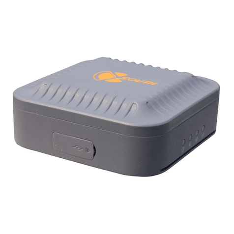
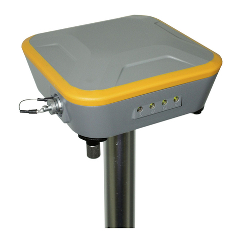
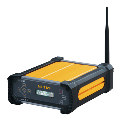
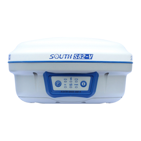
South N1 Installation guide

QUICK MANUALN1 & NAVI STATION Total Station© South Surveying & Mapping Technology CO.,LTD All Rights Reserve

1
N1 & NAVI STATION
Quick Guide
1. Menu
1.1 Menu Explore View
1.Point
2.Dist Offset
3.Plane Offset
4.Column Offset
5.MLM
6.Line &Extend Point
7.Line &Extend Angle
8. REM
1.Angle
2.Distance
3.Coordinate
1.Known Point
2.STN.Ht
3.BS Check
4.Resection
5.Point to Line
6.Free Station
7.STN setup w/o CP
1.Reduction
2.Calc.XYZ
3.Inverse
4.Area & Girth
5.Included Angle
6.Dist. Conversion
7.Angle Conversion
8.Equidistant Point
9.Triangle Calc
10.Calculator
1.Road
2.Middle-Line S.O
1.Point S.O
2.Angle & Distance S.O
3.Reference Line
4.Line
5.Reference Line S.O
6.Arc S.O
1.Free Station
2.STN setup without CP
1.H-Alignment
2.V-Alignment
1.Measure
2.Station
3.Collect
4.Stake Out
5.Job
6.COGO
7.Program
8.Setting

2
1.2 Icon info
Icon
Meaning
Photo
TServer
Star Key for Quick set
Data center
Measure mode
Target mode (Non-Prism/Prism/Sheet)
Tilt sensor
1.Order(NEZ/ENZ)
1.Unit
2.Angle
3.Distance
4.Coordinate
5.Comm.
6.Adjustment
7.Others
8.Function Key
9.Reset to Default
10.Setting
1.Min Reading(1mm/0.1mm)
2.Correction(0.14/0.2/Close)
3.Grid Factor(Scale factor/Ave Elev)
4.T-P set (Temp/Press/PPM)
5.Mode(N times/Continuous/Tracking/Single)
6.Target(Non-Prism/Sheet/Prism)
1.I Angle Set
2.2C Set
3.H-Axis Error
4.E-Bubble Adjust
5.Parameter
6.Error Display
1.Reticle Backlight
2.Soft-Keypad On/OFF
3.EDM beep
4.Measure Beep
5.Quick Code
6.Repeat Name
1.Angle(Degree/Gon/Mil)
2.Distance(Meter/US feet/Int.Feet/US feet-
inch/Int.Feet-Inch)
3.Temp Unit(°C/°F)
4.Press Unit (hPa/mmHg/inHg)
1.Key Fn/-/.
2.Key 0-9
1.Update
2.Software Info
1.Min Reading(0.1”/1”/5”)
2.V angle(V0/H0/±90)
3.Compensator(OFF/X-Axis/XY-ON)

3
2. Measure
In Measure sub menu. There
are 3 basic survey method. Angle,
Distant and Coordinate. Please
note it is not saved any measure
data under this sub menu.
In Angle, you can 0 Set or
input a certain value for
Horizontal angle setting. Also, it
allows switch vertical angle in
regular or slope percentage, right
or left of Horizontal.
In Coordinate, it allows
temporary set reflector height
and instrument height, setup STN
and BS for measurement.
3. Station
3.1 Known point.
There are 3 methods, by 2 two
known point, by angle and
multiple orient. Known point can
be call from existing job file or
manual input.
By Angle, select Azimuth and
input angle value.
In Multiple Orient, select it and
click Setting, Click Meas 1 Pt, then
add another point, press COGO
to check result. If accept it , press
Configure

4
3.2 Station Height
Set Station height by measure a
point with known height.
Input or Call a known point height
and measure it. it will calculate
new height for station, press
setting .
3.3 Back Sight Check
Check current back sight point to
shows delta value for angle or for
coordinate. Press Reset to renew
the backsight.
3.4 Resection
Resection is used for determined
the station in new position from
measure known points.
Select a geometrical graphic with
good structure is important.
After measure achieve condition
requirement, press COGO to
get calculate result.
It will show measure result and
standard deviation. If accept the
result, press STN Setup to save it
as new station point.
3.5 Point to Line
This function calculates the
unknown occupied point from
measure two points to define a
coordinate system. Can be setup
a new occupied point and
measure other points base on this AB coordinate system.

5
3.6 Free Station
An unknown point is used for
orientation. Point data collected
at this station need to be
reduction to the following
calculation to obtain the real
coordinates.
As the figure shows, STN locate in
O point, P is unknown point for
orientation, P1 is real back sight, after reduction, all points
collect in blue gird will turn to real coordinates shows at
green gird. we need to get the P1 real coordinate before
process reduction.
Operation Process:
A. Select Free station, Input STN
name, it can be manual input
or call from file.
B. Aim the backsight and press
setting
C. Then start data collect in data
collect.
D. COGO-Reduction-Free
Station, Select the BS point
No. Input or Call the real BS
coordinate you aim as
temporary before.
E. Press Reduction to finish
process. All real
coordinate will be shown in
data center.
3.7 STN setup without CP
Station setup without control point is using two free station
coordinate system, separate data collect first in each
coordinate system, then using one public point in 2 system
to reduction all points in correctly.

6
Application condition.
1. A. B is known points. But
it is not sighting STN.
2. Two temporary system
has public point C.
Operation Process
A. Station-STN setup without
CP. Input or Call STN.
B. To do data collect. During
data collect, it needs to
collect public point C.
C. Move station to next STN B,
Redo above process to do
data collect. it also needs to
collect public points C
D. COGO-Reduction-STN setup
without CP. Input STN A, B,
and public point C. select C
location and press COGO.
Then press SAVE.
Note: C location need to be select
on AB left side or right side. Wrong choose will cause
coordinate wrong.

7
4. Collect
There are 8 method to do data collect.
4.1 by Points
Input Pt Name, Code, and
reflector height first, aim target
and press Meas & Save, or directly
press Save. Press Data to check all
measure result and press Graph
to view location.
4.2 Distance Offset
Input the offset value as figure
shows, then measure offset point,
to get the final correct coordinate.
Note: All directions are
correspondent to the visual side
of operator. It can input first, also can be measure first.
4.3 Plane Offset
Measure 3 points to define a
plane. Then aim on target point. It
will calculate the coordinate
automatically. Press Data to view
and press Save.
4.4 Column Offset
Aim column left and right edge to
measure angle. Then aim column
center to measure distance to get
result, press DATA to view and
press Save.

8
4.5 MLM
MLM function is mainly used to
compute the HD/VD/SD/Azimuth
between two points.
Turn on LOCK, result will be
calculated by P1-P2, P1-P3.
Turn off LOCK, result will be
calculated by P1-P2, P2-P3.
Aim Point, Press Meas, Ang.&Dist.
Save. When measurement finish,
press COGO to check result.
4.6 Line & Extend Point
The extension function computes
extend point from the base line,
calculate the unknown coordinate
from two measure points and the
extend distance to get the
coordinate.
Measure P1 then measure P2 to
define line P1-P2, Press Dist Set to
input extend distance. + and –is
define the forward. + is P1>P2,
- is P2>P1 forward.
Press Data to view coordinate and press SAVE.
4.7 Line & Extend Angle
Computes extend point from
azimuth change.
Measure P1 and P2 to define base
line. rotate housing to correct
azimuth you want, press Save.
Note, Forward only P1>P2 direction in this method.

9
5. Stake Out
5.1 Point Stake Out
Set a coordinate for stake out, it
can be called or inputted.
Follow the guide on screen, move
prism far/near, right /left, up
/down, till to all values close to 0,
then press SAVE
5.2 Angle & Distance Stake Out
Stake out by input value of the
HA, HD or Z.
After input value, others
operation same as Point S.O.
5.3 Reference Line
Pt can be called or input.
Input the azimuth, HD, and VD.
Others operation same as Pt, S.O
5.4 Line
Define a line by call, input or
measure the start point and end
point. Then input offset distance
and stake out.
5.5 Reference Line Stake Out
Define a base Line first by call,
input or measure the start point
and end point. Then input line
offset value and rotate angle.

10
After defined base line, input
stake out point offset value and
press NEXT for stake out.
5.6 Arc Stake Out
It needs to define an Arc first.
there are 3 method to defined
Arc.
By CENTER/Start Point
By Start Pt, End Pt and Radius
By Start Pt, Arc Pt and Ent Pt
After defined Arc, Select stake out
parameter. Stake Out Point/ Arc
S.O/ String S.O/ Central Angle
S.O, input relate value such as Arc
Distance, Radius Distance, Arc
Length, String etc. then Press Next
to stake out.
6. Job
Press + icon to create a new job.
Press View info to check job
attribute.
Long press job name to open,
Delete and view job info.

11
7. COGO
7.1 Reduction
Refer to 3.6 & 3.7
7.2 Calculate XYZ
Calculate with a known point base
on direction and distance offset.
Press COGO to calculate and
Save.
7.3 Inverse
Calculate relationship between
two points. Points can be called,
input or measure.
7.4 Area & Girth
Calculate the area and girth by
points. Points can be called, Input
or measure, also it allows insert,
delete point, also allow move up
or move down points order. Press
COGO to calculate.
7.5 Included Angle
Calculate Angle by 3 points.
Points can be called, input and
measure, Press COGO to get
result.

12
7.6 Distance & Ange Conversion
Convert the unit of distance and Angle.
7.7 Average
Calculate the average value of
know points. Points can be called,
input or measure, press COGO to
get result.
7.8 Equidistance Point
Defined a line by 2 points and
input interval point, all interval
points will be calculated and save.
7.8 Triangle Calculate
Calculate triangle base on input
Angle or length.

13
8. Program
It includes Road design and Middle line stake out.
8.1 Road Design
It can be manual input H-
Alignment and V-Alignment. also,
it supports import road elements
by different file type. Such as
excel.
for H-Alignment, it needs to input
elements such as intersection
point NE. 1ST Trans Curve, 2nd Trans
Curve, Radius of Curve. Start
radius of 1st trans curve and end
radius of 2nd trans curve.
For V-Alignment, it needs to input
elements such as Mile, Height and
Radius
Import from file
Support file format: *.rd-EG Star,
*.ip-EG Star, *.xlsx-Road Elements
Form, *.rod-EG Star, *.pm and
*.jd.
Example by xlsx format:

14
8.2 Middle Line Stake Out
Finish road design first, then open
a road file, input Start Mile,
interval and offset value. Start to
Stake out ,
9. Setting
Unit
Angle
Degree/Gon/Mil/DDM
MSS
Distance
Meter/US ft/Int ft/US ft-
inch / Int.ft-inch
Temperature
°C / F °
Press Unit
hPa/mmHg/inHg
Angle
Min reading
0.1”/1”/5”
V0
V0/H0/±90°
Compensator
OFF/X-axis/Y-Axis
Distance
Min Reading
0.1mm/1mm
Correction
Close/0.14/0.2
Scale factor
Input value
Average Elev.
Input value
Grid Factor
Auto calculate base on
Scale factor and
average elevation
Temperature
Input value
Press
Input value
PPM
Auto calculate base on
temperature and press
Mode
N times/Continuous/
Tracking/ Single
Target
Non-prism/sheet/Prism
Coordinate
Order
NEZ/ENZ

15
Adjustment
I angle Set
2C Set
H-Axis Error
E-Bubble
Parameter-Constant set
Error Display
Others
Reticle backlight ON/OFF
Soft keypad ON/OFF
EDM beep ON/OFF
Measure Beep ON/OFF
Quick code ON/OFF
Repeat Name ON/OFF
Function Key
Define keys function
Reset to default
YES/NO
Setting
Update
Software Info
Star Key
Press Star key for quick set.
1. Laser Pointer ON/OFF, long press can be set auto off
time 30sec/1min On/5min On/always On.
2. Reticle Backlight ON/OFF, long press can be set level
from 1 to 4.
3. Laser Plummet ON/OFF, long press can be set level from
1 to 4.
4. Temp& Press. Manual input to reading from sensor.

16
10. Data
Press to data center, it can
manual input, edit or delete data.
Press to export or import
data.
10.1 Data export
Click “Export”, select data type
and format.
Coordinate: support TXT,DXF,DAT
and CSV format. For coordinate
order, click gear icon on right top
corner to define it.
Raw data and SA data only support export TXT format.
Select the destination folder path. Then press OK.
Export code file, Click CODE, then same as data operation.
10.2 Data Import
only support 2 format for
coordinate, TXT and DAT. The
default file folder is /Storage/
emulated/0/com_southgnss/
surveystarExpand/input. Select
the correct folder and click file you want to import. It will
ask defined import coordinate order.
Code import only support TXT file and same folder as
coordinate data.
Graph Import.
N1 and NAVI STATION support
loading graph as background.
In Data center, Graph, Click layer
icon, press + to load graph file.
It support MAP, MBTILES, KML,
KMZ,SHP,DWG,TIF,TIFF,DXF format. The graph file should be
locatein /Storage/emulated/0
/Com_Southgnss_surveystarExpand/Map folder.

17
11.GNSS Collect
For Navi Station, it allows collect data by GNSS for station
setup and data collect. It will ask OPEN GNSS or not when
enter relate menu.
for GNSS data collect, it needs to
setup GNSS parameter first. Press
Setting.
Setup Coordinate system, Press
Revise Coord.Sys to define local
system
Select datalink source. From
external mode (by CORS) or UHF
For connect CORS setting, input
IP, Port, Account, password and
access points, click CONNECT.
For UHF setting. Input match
channel, baud rate and protocol.
Press for view satellite status,
slide right side window to check
base info, point info and accuracy
factor.
In GNSS info page, press right top
corner to check satellite list
In GNSS info page, press right top
corner, press data to get the
debug data send out from COM. .
after GNSS setting, back to data
collect or station setup menu.
Check the status on right side,
when the status in FIXED, Press
ALL or DONE to save it.

18
12.Tserver
TServer is an individual application, which function is a data
dispatch platform. It read all data from hardware platform
and distribute to data collect software such as SurveyStar or
others 3rd party software.
Model: South TS Series
Connect Type: Serial Port
Device List: ttyMT3:115200
Click CONNET.
In Tserver, all setting change will
relate to Survey Star.
when connect to internet, Tserver
can be download update file to
update.
Register: Tserver need to register
so that the data collect software
can read data. If it is expired
, no hardware data send to data
collect software.
Click Register and input 36 Digits
register code to register.

SOUTH SURVEYING & MAPPING TECHNOLOGY CO., LTD.
Add: South Geo-information Industrial Park, No.39 Si Cheng Rd, Guangzhou, Chinahttp://www.southinstrument.com
This manual suits for next models
1
Table of contents
Other South Receiver manuals
