Southwest Windpower Whisper 100 User manual

WHISPER 100/WHISPER 200 24 Foot Tower Manual Document #0026 REV E
SOUTHWEST WINDPOWER 5/20/05 1
24 FOOT (7.5 m) LAND TOWER KIT
For WHISPER 100 AND WHISPER 200
WIND TURBINES
Made in the USA by:
Southwest Windpower
1801 W. Route 66
Flagstaff, AZ 86001
(928) 779-9463
Whisper is a trademark of Southwest Windpower Inc.

WHISPER 100/WHISPER 200 24 Foot Tower Manual Document #0026 REV E
SOUTHWEST WINDPOWER 5/20/05 2
24 FOOT WHISPER LAND TOWER KIT
CONGRATULATIONS! You have just received the simplest, most economical tower kit available
for your WHISPER 100 or WHISPER 200 wind turbine. This kit is designed to be very easy to
assemble and erect, however it is important that you read this manual thoroughly before beginning
assembly. If you have any questions on proper installation or usage please call either Southwest
Windpower or your dealer for more information.
Notice: This information is believed to be accurate, however, Southwest Windpower assumes no
responsibility for inaccuracies or omissions. The user of this information and product assumes full
responsibility and risk. All specifications are subject to change without notice.
CONTENTS Page
Introduction 3
Safety 3
Parts List 4
Tools Needed 5
Step 1: Site Selection 5
Step 2: Tower Pipe Selection 6
Step 3: Tower, Base and Anchor Layout 7
Step 4: Tower Base Assembly 8
Step 5: Guy Wire Anchor Installation 9
Step 6: Assembly of Tower and Turbine 12
Step 7: Attachment of Guy Wires 13
Step 8: Raising the Tower 14
Step 9: Final Adjustment of Guy Wires 17
Step 10: Lowering the Tower 17

WHISPER 100/WHISPER 200 24 Foot Tower Manual Document #0026 REV E
SOUTHWEST WINDPOWER 5/20/05 3
Introduction
This tower kit is designed specifically for the Southwest Windpower WHISPER 100 and
WHISPER 200 wind turbines. To our knowledge this is the most economical and user-friendly
tower kit available for the Whisper wind turbines. One level, guy wire supported construction
allows the use of lightweight tubing while providing plenty of strength, even in high wind
conditions. With the help of a winch, beast of burden or vehicle, two people can easily erect the
tower in a few hours. All that is required is the necessary tubing and the proper anchors for your
type of soil. At least two people should be present to safely raise the tower.
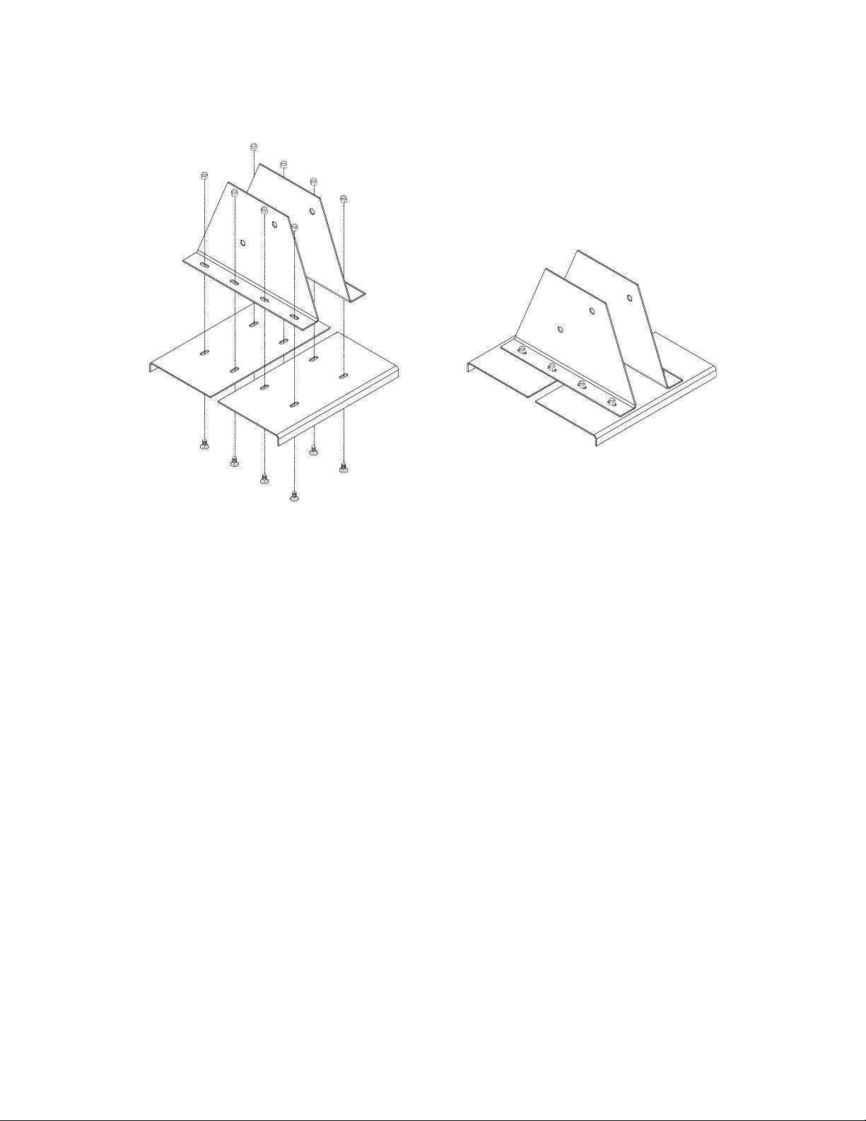
This Whisper tower kit includes a custom made galvanized base with separate pivots for both the
tower and gin pole (not used on 24 foot tower). The tower base has a footprint of 16 inches square.
In most cases a concrete pad for the tower base is not necessary.
A simple extruded aluminum coupling clamp allows the use of different wall thickness of tubing,
depending on site requirements. Threaded coupling points are eliminated, allowing lighter
materials to be used with the same or greater strength than a threaded pipe tower. The guy wire
attachment clamps onto the upper mast section. This reduces the number of pieces of tubing used
to construct the tower and reduces the stresses concentrated at this point. Pre-cut and swaged guy
wires eliminate wire measuring and cutting. We believe this kit and assembly method is the easiest
way possible to put the WHISPER 100 or WHISPER 200 up in the air.
Thank you for purchasing our products and for your interest in renewable energy. We are confident
that you will enjoy the benefits of your wind powered electrical system for many years to come. If,
after reading this manual, you have any further questions please contact your local dealer or
Southwest Windpower and we will do our best to assist you.
Safe Installation
Safety is the most important consideration to take into account when installing a tower and
wind turbine. It is very important to remember that any wind turbine has high speed spinning
parts and can be very dangerous if not installed properly! Be sure the tubing or pipe used for the
tower is of adequate strength, all bolted connections are tightened to the proper torque and the guy
wire anchors are suitable for your conditions, terrain and size of tower. All of these elements are
explained in further detail later in this manual. Important! Choose a very calm day to do your
installation. A gust of wind at the wrong moment could cause VERY SERIOUS
PROBLEMS!
PLEASE…. READ THIS ENTIRE MANUAL BEFORE DOING ANYTHING!

WHISPER 100/WHISPER 200 24 Foot Tower Manual Document #0026 REV E
SOUTHWEST WINDPOWER 5/20/05 4
24 Foot (7.5 m) Whisper Tower Kit
Parts List
Your tower kit includes: Quantity
Tower Base 1
Guy Wire set 1
3/8” x 2” Bolts 2
3/8” x 3 ½” Bolts 2
3/8” Lock-nuts 12
Cable Thimbles 4
Cable Clamps 12
Pivot Bolt and Nut 1
Tower Insert (included with turbine) 1
Tower Base Coupler 1
3/8” Carriage Bolts 8
Please inspect the contents to see that all parts are present and to familiarize yourself with the
pieces before beginning assembly.
(included with turbine)

WHISPER 100/WHISPER 200 24 Foot Tower Manual Document #0026 REV E
SOUTHWEST WINDPOWER 5/20/05 5
Necessary items not included in this kit:
Earth Anchors (explained further in the “Anchors” section of this manual, pp. 9-12)
Tubing or Pipe for Tower (p. 6)
Ground Rod and Clamp
Lightning Arrestor*
Electrical Wire
Wire Connectors (preferably copper split bolts)
Pipe Insulation (to prevent wire “rattle” inside pole) *
Electrical tape
* Optional items (these are explained in more detail in their relevant assembly sections)
Tools Needed:
Round or Half Round File Pliers
Carpenters Level (optional) (2) 9/16” (15mm) Wrenches /Sockets
Torque Wrench Sledge Hammer
15/16” (24mm) Wrench Large Adjustable wrench
Sawhorse Ladder or 10 foot (3 m) 2x6 or 2x8
Lifting Rope 3/8” or 10mm Corded or Cordless Drill Motor
3/8” or 10mm Metal Cutting Drill Bit
Step 1: Site Selection
Site selection is the most important factor affecting the performance of your wind turbine!
The energy in the wind is the kinetic energy of the moving air mass. What a wind turbine does is
convert some of that kinetic energy into rotational energy that can then be converted to electricity.
The formula for the amount of power in the wind is a cube function of the wind speed. This means
basically that an increase in wind speed of 10% (say from 9 mph to 10 mph) will result in
approximately a 37% increase in the power available from the wind and a similar increase in
turbine performance. In almost all locations the wind speed increases as you get higher off the
ground. This is why a tall tower is very important at most wind sites. As a rule, the turbine should
be mounted as high in the air and as far away from obstructions as is possible.
To find the best location to erect your tower and wind turbine, study the available area and take
note of how the prevailing (most common) winds blow through it. If there are trees, buildings, hills
or other obstructions take note of how high they are and where they are in relation to the prevailing
wind direction. The best site for your tower and turbine will be upwind and above any obstructions
that may exist. If there are houses or trees in the surrounding area a good rule of thumb is to mount
the turbine at least 15 feet above any obstructions within 500 feet (150 m) of it.
The next consideration in siting your tower and turbine is the distance from the turbine to your
batteries. The shortest distance will require the least amount of wire, allow use of the most
economical (smallest) wire and reduce the amount of power lost through the wiring. If a long

WHISPER 100/WHISPER 200 24 Foot Tower Manual Document #0026 REV E
SOUTHWEST WINDPOWER 5/20/05 6
distance is required between your tower and the batteries it will be necessary to use heavy gage
wire to reduce the resistance of the wire. The power consumed buy the wires can be calculated
using the formula:
Power = Current xCurrent x Resistance
Since the resistance of the wire is directly proportional to its length, making the run shorter will
dramatically reduce the amount of power “lost” in the wires. See your turbine owner’s manual for
wire sizing charts.
Please refer to the section on “Tower, Base and Anchor Layout”. The amount of space available to
assemble and raise the tower may also affect where your tower can be placed
Step 2: Mast and Hardware Selection
Because of the high cost of shipping and the widespread availability of the tubing or pipe used for
our towers, these materials are not provided by Southwest Windpower. These materials are readily
available through most chain link fence suppliers or plumbing companies and will cost much less
when purchased locally than if we were to try to ship them from our factory.
The “Whisper” land tower kit is designed to use a 2.875 in. (73 mm) outside diameter pipe. This is
the same outside diameter as 2 ½ in. steel water pipe where the “2 ½” is a nominal size indicating
an outside diameter that is actually 2.875 in. Whether the pipe is “schedule 20”, or “schedule 40”,
the outside diameter will be the same and the schedule number determines the wall thickness of the
pipe. Use only structural steel for this tower! Never use electrical conduit!
The design of this tower kit allows steel pipe (or tubing) of various different wall thickness to be
used depending on its availability and on the severity of the wind at your site location. Use the
following table to determine the acceptable pipe size(s) for your tower and wind severity. In most
locations structural pipe with a wall thickness of .090 inches (3 mm) is sufficient for the conditions
and preferable in terms of cost and ease of assembly. We recommend either “CQ-40” or “S-40”
fence pipe available from any chain link fence supplier. Electrical conduit or plastic tubing should
never be used in your tower assembly, since it is designed to be bent easily, not for strength.
Use the following table for Pipe / Tubing wall thickness guidelines:
Maximum
Wind Speed
80 mph. (135 kph)
100 mph. (160 kph)
120 mph. (190 kph)
Recommended
Wall Thickness
.090 inch (2.3 mm)
.120 inch (3 mm)
.140 inch (3.6 mm)
Pipe
Schedule
CQ-20
CQ-40
S-40
Pieces of Pipe Needed:
(1) 24 foot (7.3 M) length of pipe for tower (wall thickness selected for local conditions)

WHISPER 100/WHISPER 200 24 Foot Tower Manual Document #0026 REV E
SOUTHWEST WINDPOWER 5/20/05 7
***In some areas there are subsidies and grants available for installing renewable energy systems.
If you live in one of these areas and need an engineering analysis for this tower assembly to satisfy
your local authorities please contact us. We have an engineering analysis available for this tower
kit.
Step 3: Tower, Base and Anchor Layout
This tower kit should only be assembled on a calm a day (no wind). The tower base and anchors
should be laid out as described in the drawing below.
The tower will be assembled laying on the ground and then tilted up into position.
If the tower is being erected on a slope it will be much easier to raise the tower if it is assembled to
the uphill side of the base as it will already be part way up as it is erected. In this case the two
“side” anchors should be at the same height or elevation on the hill as the tower base. The two
remaining anchors should be directly uphill and downhill from the tower base.
Be sure that the anchor points and base position are in a line when sighted from anchor to anchor.
This will insure that the forces on the guy wires are balanced properly, make final guy wire
adjustments simpler and will help a great deal during the actual raising of the tower. The side
anchors and tower base should also be at the same elevation. If either of these requirements are not
met, the guy wires will either tighten excessively or go slack as the tower is raised. If the guy
wires tighten excessively the tower may buckle and collapse, causing possible injury or even
death and at the very least, damage to both the tower and the turbine. Carefully read the section
on raising the tower for further instructions on making the proper adjustments in these
situations.

WHISPER 100/WHISPER 200 24 Foot Tower Manual Document #0026 REV E
SOUTHWEST WINDPOWER 5/20/05 8
Step 4: Tower Base Assembly
To assemble the tower base:
1) Start by matching the two “upright” pieces together as shown above.
2) Insert the large pivot bolt through the holes to assure proper alignment and install its nut
finger tight. The two uprights should be assembled 4” apart. The tower base coupler can be
used to help set this distance.
3) Bolt the two uprights to the two base plates using the carriage bolts provided (install the
bolts from below, nuts from above).
4) Torque the nuts to 30-35 ft-lb (40-47 N-m)
5) Set tower base at desired location with lower pivot holes toward tower assembly direction.
6) Secure base with stakes or steel re-bar driven into the ground or bolts in concrete.

WHISPER 100/WHISPER 200 24 Foot Tower Manual Document #0026 REV E
SOUTHWEST WINDPOWER 5/20/05 9
Step 5: Guy Wire Anchor Installation
There are four types of anchors that are most commonly used with our towers; screw in “Auger”
type anchors, hammer driven “duckbill” anchors, cast concrete anchors and expansion bolts (for use
only in solid rock). What anchor should be used depends on the soil type that the anchors will
be placed in. See the following table for our suggestions:
Soil Type
Sand
Loose Gravel
Loam
Clay
Rocky Soil
Gravely Soil
Solid (Soft) Rock
Solid (Hard) Rock
Recommended Anchor
Concrete
Concrete
Auger
Duckbill
Duckbill
Auger or Duckbill
Large, Long Expansion Bolt
Smaller Expansion Bolt
Alternatives
None
None
Duckbill, Concrete
Auger, Concrete
Concrete
Concrete
Large Eye Bolt + Cement
None
The loads on a single anchor can exceed 1,500 lb. in a 100-mph gale. Make sure that the anchors
chosen can withstand at least this much force or the tower will have to be lowered during storms.
Augers and Duckbill anchors are frequently available at mobile home supply stores. Augers are
also available the dealer where your turbine was purchased or from SWWP. Expansion bolts for
anchoring in solid rock can be purchased at most hardware stores.
Augers: If the soil conditions make their use feasible, augers are the simplest anchors to install.
Augers screw into the ground using either a piece of wood, pipe or rod as a “cheater bar”. If a
mistake is made or if the tower must be removed an auger can be “unscrewed” out of the ground
and reused. They depend on the soil holding together for their strength are not suitable for sand or
loose gravel. If the soil is rocky or clay-like you may have difficulty screwing them in.
An auger is usually installed by screwing it straight into the ground a few turns to get it started and
then tilting it to the desired angle once it is into the ground a few inches. A substantial downward
pressure is usually necessary to get an auger started. Screw the augers in as far as possible for the
greatest strength.

WHISPER 100/WHISPER 200 24 Foot Tower Manual Document #0026 REV E
SOUTHWEST WINDPOWER 5/20/05 10
Augers depend on the ability of the soil to hold together for their strength. If augers cannot be
screwed in, simply digging a hole and burying them will not work. We recommend buying augers,
and if they cannot be screwed in properly, a hole can be dug and the auger can then be cast in the
concrete. This will provide a good loop for guy wire attachment and make an excellent anchor in
the concrete.
Duckbill Anchors: Duckbill anchors consist of an anchor attached to a cable with a loop on the
end. They are driven into the ground using an anchor driver, which is a steel rod with either an
enlarged striking surface (for a large hammer) or an attachment for a jackhammer or impact driver.
The anchor driver fits into the anchor and holds it straight while it is being driven into the ground.
Once the anchor is sufficiently deep in the ground, the driver is withdrawn and the anchor cable is
pulled a short distance to “set” the anchor. As the anchor is being set it will rotate perpendicular to
the hole made as it was driven in, making it very difficult to move any further.
Please note that once a duckbill anchor is set in place it cannot be removed without digging it out.
Buried Concrete: A buried concrete anchor may be the only solution if the ground is loose gravel
or sand or if it is too rocky for an auger or duckbill to be driven in. Buried concrete anchors work
well in any situation other than solid rock. A hole must be dug in the ground at the desired anchor
point. One good tactic is to purchase either augers or duckbills and if they cannot be used as
intended, then dig holes and cast them in concrete. Otherwise some other means of attachment
must be created for the guy wires, such as a loop of steel reinforcing bar (re-bar) or chain.

WHISPER 100/WHISPER 200 24 Foot Tower Manual Document #0026 REV E
SOUTHWEST WINDPOWER 5/20/05 11
Holes for concrete anchors should be at least 24 in. (60 cm) in diameter and at least 36 in. deep.
The attachment should be placed in the hole and concrete or cement poured around it to a depth of
at least 12 in. (30 cm). Once the concrete has cured (see instructions on supplied with your
concrete for curing times) it should be buried before use.
Anchoring in Rock: If your tower site has large rocks around it or is located on solid rock,
expansion bolts in the rock may be the best means of anchoring your guy wires and base tube. A
hole is drilled into the rock and the bolt is placed in the hole with an attachment hanger, a piece of
chain or other loop to connect to the guy wires.
For expansion bolts to work properly the rock must be of good quality and not fracture easily. If the
rock quality is poor a larger deeper hole must be drilled and a large eye-bolt cemented into it. For very
hard rock such as granite and basalt, a ¼ inch (6 mm) diameter bolt 1 ½ inch (4 cm) deep can be used.
For slightly softer rock such as dacite, welded tufts and some denser varieties of sandstone, a 3/8-inch
(10 mm) diameter bolt 3 to 4 inches (7-10 cm) deep should be used.

WHISPER 100/WHISPER 200 24 Foot Tower Manual Document #0026 REV E
SOUTHWEST WINDPOWER 5/20/05 12
For softer types of rock, such as sandstone or limestone, a hole 1-inch (25 mm) diameter and 8 inches
(20 cm) deep can be drilled and an eye-bolt 5/8 inch (16 mm) in diameter cemented into it. The cement
should be mixed just thin enough to pour and poured into the hole before the bolt is installed (a straw
inserted to the bottom of the hole before pouring will help prevent a bubble from forming). This will
help to insure that the cement goes to the bottom of the hole and help prevent bubbles that may
compromise the strength of the attachment. If expansion bolts are to be used, follow the instructions
supplied with the bolts. There are several different types of expansion bolts that are installed using
different methods.
Step 6: Assembly of Tower and Turbine
The tower is assembled laying on the ground and then lifted onto a sawhorse or large box so that
the turbine can be mounted to it.
1) Remove pivot bolt from tower base and insert it through the pivot holes in the tower base
coupler.
2) Install the tower base coupler onto the tower pipe so that the pivot bolt just touches the end
of the tower pipe. Torque the two pinch bolts to 45-50 ft-lb. (60-68 N-m) and withdraw
pivot bolt
3) Lay the tower pipe on the ground and locate the base coupler into the tower base.
4) Install the pivot bolt and nut through the base and coupler. Tighten so they are just barely
snug, not tight, against the tower base.
5) Raise the turbine end of the tower pipe and set it on a saw horse or other supporting object.
The end of the tower should be at least 3-4 feet (1 m) off the ground. Drill holes in tower
pipe using supplied template. A tower drilling template is included as the last page of this
manual.
6) Install the round tower insert onto the turbine’s yaw shaft. Tighten the two set screws to 4-5
ft-lb. (5-7 N-m)

WHISPER 100/WHISPER 200 24 Foot Tower Manual Document #0026 REV E
SOUTHWEST WINDPOWER 5/20/05 13
7) Install the turbine (electrical) wires to the turbine using split bolts or solder. Insulate well
with electrical tape or heat shrink tubing.
8) Install the guy wire set onto the tower pipe. The center of the clamping piece should be
located 5 feet (1.52 m) from tower top. Torque the two bolts to 40-45 ft-lb. (54-60 N-m)
9) Run the turbine wires through the tower pipe. Taping the ends of all three wires together
makes this easier. Lift the turbine into position and install the tower insert on the turbine
into the end of the tower. It will help to have someone pull the slack out of the turbine
electrical wires as the turbine is being moved into position.
10) Make sure the bottom of the tower insert is touching the top end of the tower pipe. Insert
and torque all four insert mounting bolts (M8 x 20mm) to 10-11 ft-lb. (12-14 N-m)
repeating any tightening sequence used at least four times to insure the lock washer is
flattened.
Step 7: Attaching Guy Wires to Anchors
With the assembled tower laying on the ground the guy wires at the sides and rear of the tower
should now be attached. Leave about 3 in. (7.5 cm) of slack in the wires to allow for any
misalignment or unnoted elevation differences (the wires will be adjusted more precisely later).
The side wires can be pulled to their anchors and attached using the wire rope thimbles provided
with your tower kit.

WHISPER 100/WHISPER 200 24 Foot Tower Manual Document #0026 REV E
SOUTHWEST WINDPOWER 5/20/05 14
Note: The thimbles may need to be spread open to install them on your anchors. This can be done
with a pair of pliers and the end of one of the tower tubes. Be sure to press the open end of the
thimbles back together (with pliers) before attaching the guy wires.
The rear guy wire length can be estimated by pulling it to a side anchor and placing a piece of tape
on the wire at the distance of the side anchor. The rear wire will then be attached to its respective
anchor at the point marked by the tape. This should make their length approximately correct when
the tower is up (again these will be readjusted, so don’t worry about a couple of inches (5cm) one
way or the other). Make sure that none of the guy wires are crossed and that the side wires are
straight with no rear wires on top of them. Run the tail of each guy wire through the second clamp
twice, forming a safety loop. Attach all of the side and rear wires securely as shown in the drawing
with two clamps on each wire. Use 15-16 ft.-lb. (20-21 N-m) of torque on each nut. It is important
(for good strength) that the saddle part of each clamp is on the loaded (tower) side of the guy wire.
MAKE SURE THAT ALL GUY WIRES ARE SECURE BEFORE PROCEEDING!
At this point the turbine should be propped up on a box, chair, stool or milk crate so that the blades
are not damaged when they are installed. Mount the blades onto the turbine at this time.
Step 8: Raising the Tower
Before attempting to raise the tower make sure that all side and rear guy wires are attached
and that all cable clamps are tight. Also be sure that the two bolts on the guy wire hanger are
tight.

WHISPER 100/WHISPER 200 24 Foot Tower Manual Document #0026 REV E
SOUTHWEST WINDPOWER 5/20/05 15
1) Once the rear and side guy wires are attached. Attach the “lifting” guy wire to a pulling
rope, chain or cable attached to a vehicle, winch or work animal. (pulling rope should test
to at least 1,000 lb or 450 kg for safety). At least fifty feet (16 m) of rope will be needed to
erect this tower.
2) Run the rope and lifting wire over the end of the 2x6 or 2x8 or ladder as shown on the
following page to form a crude, but effective gin pole (see drawings on following page).
3) At this time all persons nearby should move to a safe distance (at least 30 feet (10 m)) from
the tower while it is being raised.
4) Move the vehicle forward slowly to take the slack out of the lifting wire. Slowly proceed
until the tower lifts off of the sawhorse. Pull and stop every 15 degrees (towers angle to
horizontal) or so and observe the side guy wires. If they start getting too tight, stop the
vehicle and slowly reverse to set the tower back down. This is usually caused by the ground
at the base being slightly higher than the ground at the side guy wire anchors, or if the
anchors and the base are not in a straight line. If this occurs immediately lower the tower
back to the ground and adjust the side guy wires a few inches looser.
Failure to adjust the guy wires properly before raising the tower may cause the tower to
buckle and collapse, seriously damaging the turbine and tower and possibly causing serious
personal injury or death!

WHISPER 100/WHISPER 200 24 Foot Tower Manual Document #0026 REV E
SOUTHWEST WINDPOWER 5/20/05 16
5) The board or ladder will fall out of the way after it has done its job. This is ok, just
remember to put it back in position when lowering the tower.
6) Continue forward until tower is vertical, stop vehicle, set brake, leave in gear and shut off
engine. Be sure not to pull too far or the tower may buckle and collapse.
7) Remove lifting wire from rope and vehicle and attach to lifting side anchor as described in
step 7 (attaching cables to anchors). Maintain some tension on the lifting wire while the
cable is being attached to prevent tower from falling back down.
8) At this point the tower should be checked for guy wires that are slightly too tight or too
loose. Guy wires that are too tight will cause the tower to bow. If they are too loose the
tower will usually sway back and forth a bit. The proper tension is where there is no tension
and no slack. This is easily achieved by hand without turnbuckles. Correct any obviously
mis-adjusted wires by loosening their cable clamps one at a time, adjusting the wire and re-
tightening the clamps.

WHISPER 100/WHISPER 200 24 Foot Tower Manual Document #0026 REV E
SOUTHWEST WINDPOWER 5/20/05 17
Step 9: Final Adjustment of Guy Wires
Check to see if any of the guy wires are too tight and are causing the tower to bow. A tower with
slightly loose wires is safer than a tower with wires that are too tight. If there are, determine which
wire(s) are too tight (the wires act in pairs) and release the tension on one of the wires. To relieve
tension on a wire, loosen the two cable clamps until the cable can be slid through them and feed in
just enough slack to relieve the tension.
The tension on the wires should be very light and can be set by pulling the wire by hand. It is easy
to over tighten the guy wires, even by hand. Once adjusted, be sure to re-tighten the cable clamp
nuts. Repeat this until the tower is no longer bowed.
Now walk a short distance from the tower and look to evaluate whether the tower is straight or
leaning to one side (a carpenter’s level held against the tower can be helpful for this). You will
need to loosen one wire and tighten the wire opposite to it. Check the tower straightness and repeat
the process until the tower is straight.
When you are finished, make sure that all the cable clamps are tight. If the tower is to be lowered,
only unclamp the cable on the lifting wire side so that when the tower is re-erected only that cable
will need to be readjusted.
Grounding
To properly ground the tower to the earth a ground rod (usually copper plated steel) should be
installed as close to the tower base as possible. A #10 AWG or larger wire should be attached to
the tower pipe or base coupler near the bottom of the tower with its other end clamped to the
ground rod.
Maintenance
Periodically check to see that the guy wire tension is set properly. Typically there is no other
maintenance required for this tower. Keep your setup kit in a safe place in case the tower needs to
be moved or the turbine requires service.
Step 10: Lowering the Tower
If it is necessary to lower your tower for any reason, follow these steps:
1) Disconnect your turbine wires at the controller.
2) “Short” the wires together to stop the turbine from spinning
3) Disconnect the guy wire on the lifting wire side only. Attach it to the winch or vehicle.

WHISPER 100/WHISPER 200 24 Foot Tower Manual Document #0026 REV E
SOUTHWEST WINDPOWER 5/20/05 18
4) Position a sawhorse where the tower is expected to come to the ground to protect the turbine
blades from damage.
5) Tip the tower by hand until the lifting wire is taut and supporting the tower.
6) Position a ladder under the lifting wire to act as a gin pole while lowering.
7) Slowly lower the tower until it is resting on the saw horse.
Other manuals for Whisper 100
1
This manual suits for next models
1
Table of contents
Other Southwest Windpower Wind Turbine manuals