7 8
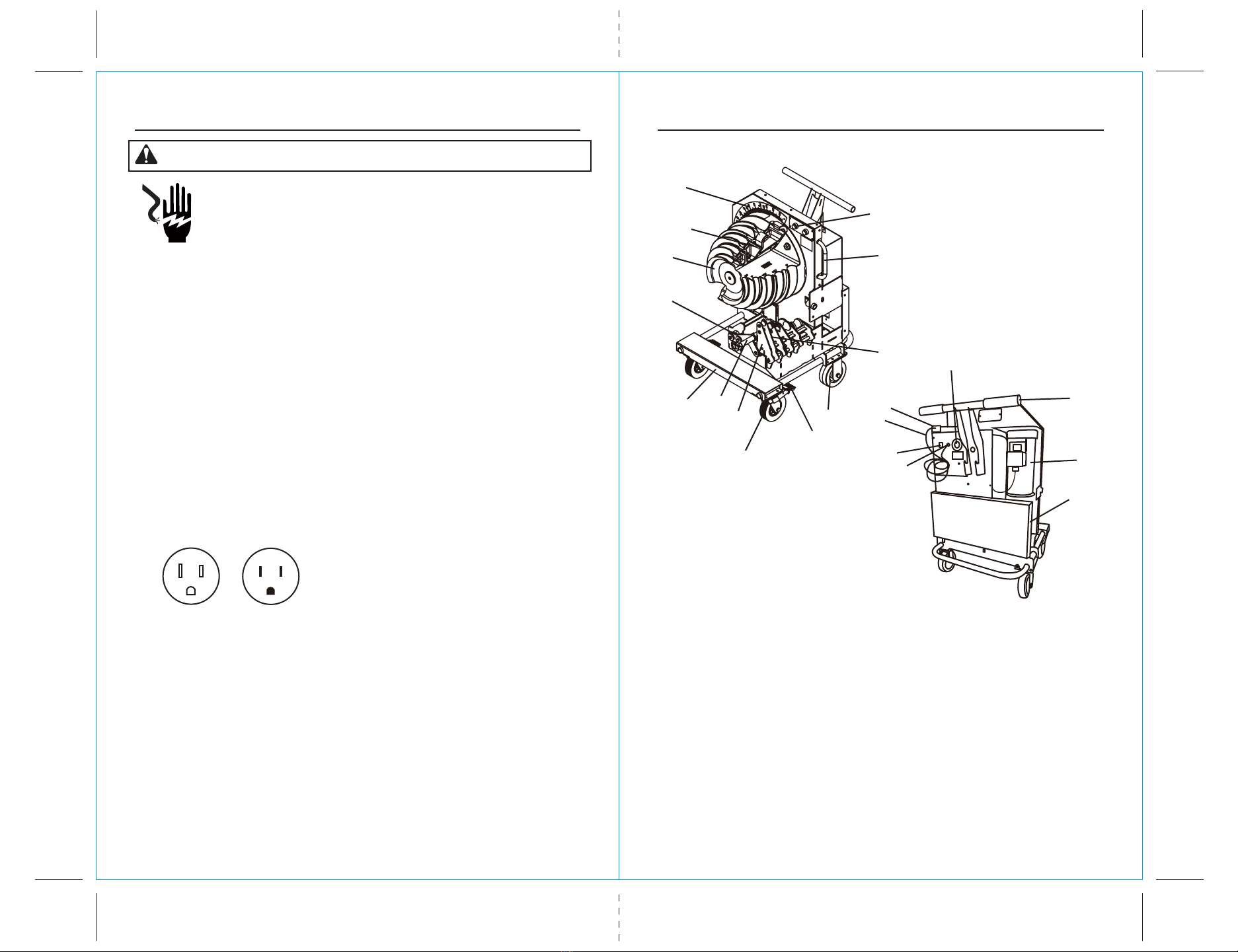
• Use only three-wire, 12 AWG extension cords that have three-
prong grounding-type plugs and three-hole receptacles that
accept the tool`s plug.
• Do not use extension cords that are longer than 30m(100``).
• Repair or replace damaged extension cords.
IMPORTANT SAFETY INFORMATION IMPORTANT SAFETY INFORMATION
FAILURE TO OBSERVE THIS WARNING COULD RESULT
IN SEVERE INJURY OR DEATH.
WARNING:
• Select the appropriate shoe groove and support roller for the
type and size of conduit before bending.
• Do not bend conduit over 96 degrees. Overbending could result
in the other shoe hook colliding with the conduit.
FAILURE TO OBSERVE THIS WARNING COULD RESULT
IN SEVERE INJURY OR DEATH.
CAUTION
• Inspect the bender before use. Replace worn, damaged, or
missing parts with Southwire replacement parts. A damaged or
improperly assembled component could break and strike nearby
personnel.
CAUTION
• Adjust fork spacing to match fork tubes on bender. Ensure
front wheel brakes are engaged before inserting forks into fork
tubes.
FAILURE TO OBSERVE THESE WARNINGS COULD
RESULT IN SEVERE INJURY OR DEATH.
WARNING
• Conduit moves rapidly as it is bent. The path of the conduit must
be clear of obstructions. Be sure clearance is adequate before
starting the bend.
• Wear proper apparel. Do not wear loose clothing, gloves, neckties,
rings, bracelets, or other jewelry which may get caught in moving
parts. Nonslip footwear is recommended. Wear protectice hair
covering to contain long hair.
• Do not force rollers or alter tool. It will do the job better and sager
at the rate for which it was designed.
• Use the right tool. Do not force tool or attachment to do a job for
which it was not designed.
• Use this tool for the manufacturer`s intended purpose only. Use
other than that which is instructed in this manual can result in
injury or property damage.
FAILURE TO OBSERVE THESE PRECAUTIONS MAY
RESULT IN INJURY OR PROPERTY DAMAGE.
CAUTION
• Maintain tools with care. Keep tool clean for best and safest
performance. Follow instructions for lubricating and changing
accessories.
• Check damaged parts. Before further use of the tool, a guard or
other part that is damaged should be carefully checked to
determine that it will operate properly and perform its intended
function. Check for alignment of moving parts, binding of moving
parts, breakage of parts, mounting, and any other conditions that
may affect its operation. A guard or other part that is damaged
should be properly repaired or replaced.
FAILURE TO OBSERVE THESE PRECAUTIONS MAY
RESULT IN INJURY OR PROPERTY DAMAGE.
Extension Cords