Southwire Sumner GH3/4T-15 User manual

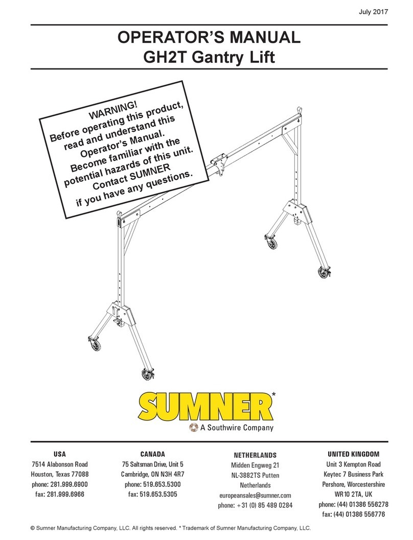
OPERATOR’S MANUAL
GH3/4T Gantry Lift
July 2017
WARNING!
Before operating this product,
read and understand this
Operator’s Manual.
Become familiar with the
potential hazards of this unit.
Contact SUMNER
if you have any questions.
*
USA
7514 Alabonson Road
Houston, Texas 77088
phone: 281.999.6900
fax: 281.999.6966
UNITED KINGDOM
Unit 3 Kempton Road
Keytec 7 Business Park
Pershore, Worcestershire
WR10 2TA, UK
phone: (44) 01386 556278
fax: (44) 01386 556776
NETHERLANDS
Midden Engweg 21
NL-3882TS Putten
Netherlands
europeansales@sumner.com
phone: +31 (0) 85 489 0284
CANADA
75 Saltsman Drive, Unit 5
Cambridge, ON N3H 4R7
phone: 519.653.5300
fax: 519.653.5305
© Sumner Manufacturing Company, LLC. All rights reserved. * Trademark of Sumner Manufacturing Company, LLC.

2
OWNER’S RESPONSIBILITIES
Throughout this publication, the words WARNING, CAUTION
and IMPORTANT will be used to alert the user to special in-
structions concerning a particular operation that may be
hazardous if performed incorrectly or carelessly.
OBSERVE THEM CAREFULLY !!
WARNING Hazards or unsafe practices which could
result in severe personal injury or death.
CAUTION Hazards or unsafe practices which could
result in minor personal injury, product
or property damage.
IMPORTANT Indicates information or instructions that
are necessary for proper operation and/
or maintenance.
Index
Introduction.........................................................................................3
Gantry Components ...........................................................................3
Operator Safety Instructions...............................................................3
GH3/4T Gantry Lift Assembly......................................................... 3-6
1. Erect A-Frame..........................................................................4
2. Assemble Components........................................................ 5-6
Gantry Height Adjustment............................................................... 6-7
1. Unlock casters .........................................................................6
2. Adjust lifting handle location.....................................................6
3. Remove locking pins............................................................ 6-7
Gantry Span Adjustment.....................................................................7
Moving Gantry Lift ..............................................................................7
GH3/4T Gantry Specications............................................................8

3
Introduction
Thank you for choosing Sumner’s GH3/4T Gantry Lift
to meet your material lifting needs. The GH3/4T Gantry
Lift has a load capacity of 3/4 metric tons (750 kg) or
1,650 lbs. Following proper procedures for use and
maintenance of Sumner’s GH3/4T Gantry Lift de-
scribed in this manual will provide you with years of
dependable service.
Gantry Components
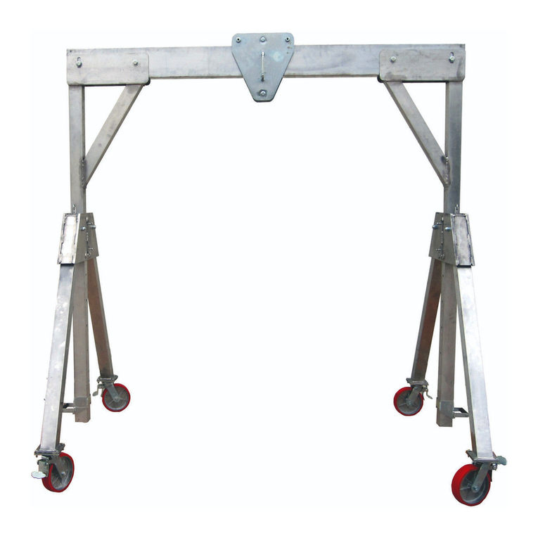
Sumner’s GH3/4T Gantry Lift consists of the below
components. Before attempting to assemble Gantry
Lift be certain that all components are available.
• 2 - A-frames
• Cross Beam (3m, 4m, 5m, 8', 10', 12' or 15')
• Trolley
• Attaching hardware (4 bolts, 4 nuts & 8 washers)
Operator Safety Instructions
IMPORTANT
Read and understand this manual
prior to operating or performing main-
tenance on this lift.
1. ALWAYS Inspect all equipment prior to use to
make certain it is in proper working order.
2. NEVER use unit If any part of equipment appears
damaged or does not assemble properly.
3. ALWAYS use only Sumner replacement parts. Any
replacement parts not supplied by Sumner
Manufacturing will severely compromise the
quality and safety designed into this unit as well as
invalidate the warranty.
4. As a precaution, ALWAYS wear proper
clothing when operating unit, including hard hat,
work gloves and safety shoes.
5. ALWAYS avoid horseplay around equipment, and
keep bystanders at a safe distance. Do not allow
children to operate this unit and always keep them
out of work areas.
6. NEVER misuse the unit. Perform only the
functions for which the unit is designed. Never at-
tempt to operate the equipment at more than the
recommended capacity.
7. No riders on unit. This unit was designed for
material lifting purposes ONLY and is not designed
to function as a personnel lift or carrier.
8. NEVER stand under an elevated load.
9. NEVER exceed rated load capacity.
10. NEVER operate during high winds or electrical
storms.
11. NEVER use Gantry lift to support ladders or other
climbing devices.
12. When possible ALWAYS move loads by moving
the trolley on the Gantry cross beam while the lift
is stationary with all casters locked.
13. It is not recommended to move the Gantry lift with
a load. When moving the Gantry lift with a load
be sure to secure trolley in center of cross beam
to evenly distribute the weight across the unit and
lower load as close to the ground as possible.
Move lift by pushing the Gantry, not the load.
14. NEVER leave a load on the Gantry lift
unattended.
15. ALWAYS adjust A-frame heights prior to attaching
a load and make certain cross beam is level prior
to attaching a load. See instructions in this manual
on how to adjust A-frame heights.
16. NEVER adjust A-frame heights without rst
securing trolley to center of cross beam.
17. ALWAYS use Gantry lift on a hard, level, smooth
surface that is free of debris and obstructions. Be
certain the surface the Gantry is on can support
the full weight of the intended load.
18. NEVER move a fully assembled Gantry lift using a
fork lift or other lifting device.
19. NEVER use Gantry lift as an electrical ground.
20. ALWAYS ensure load is not secured to the ground
before attempting to lift it.
GH3/4T Gantry Lift Assembly
The following tools are required to properly assemble
the GH3/4T Gantry Lift:
• 1" wrench
• 1" socket wrench
• Ladder

4
1. Erect A-Frame
Begin with the A-frames lying at on the ground.
Assemble Gantry following instructions below.
1. To extend one leg push the red leg locking button.
The leg is now free to extend.
2. Extend each leg until the button clicks in place
locking the leg in the open position.
Repeat process for second A-frame.
3. Lock all casters on both A-frames by pushing down
on caster brake mechanism.
4. Casters can be locked at 90 degree angles to make
transport easier. To lock caster at a 90 degree
angle, flip the caster lock lever as indicated in
above illustration.
5. Position A-frames as necessary at either end of
cross beam.

5
2. Assemble Components
1. Lay out cross beam in a cleared area. Place one A-
frame at either end of the cross beam as shown.
2. Lift one side of cross beam onto A-frame and line
up outside bolt hole on A-frame with desired bolt
hole on cross beam. Place bolt through bolt hole on
A-frame and cross beam with washers on either
side of the bolt. Loosely tighten so A-frame can
swivel when A-frame is erected.
3. Place trolley at the opposite end of the cross beam.
Center trolley on cross beam and tighten with set
screw.
4. Lift cross beam end without bolt inserted and
position on A-frame lining up outside bolt hole on
A-frame with desired bolt hole on cross beam.
5. Place bolt through bolt hole on A-frame and cross
beam with washers on either side of the bolt.
Loosely tighten so A-frame can swivel when A-
frame is erected.
6. Erect one A-frame and line up inside bolt hole on
the A-frame with corresponding bolt hole on the
cross beam. Using a ladder, place bolt through bolt
hole on A-frame and cross beam. Tighten both sets
of bolts.
CAUTION
Be certain both casters on both A-
frames are locked before erecting
A-frames.

6
7. Erect second A-frame and line up inside bolt hole
on the A-frame with corresponding bolt hole on the
cross beam. Place bolt through bolt hole on A-
frame and cross beam with washers on either side
of the bolt. Fully tighten both sets of bolts.
Gantry Height Adjustment
1. Unlock casters
Unlock both casters on the A-frame for which you will
be adjusting the height.
CAUTION
NEVER attempt to adjust the height
while the lift is holding a load.
CAUTION
Be certain trolley is centered and held
in place with set screw before
attempting to adjust A-frame height.
2. Adjust lifting handle location
Release the plunger pin on the lifting handle and slide
handle to desired position most convenient for lifting or
lowering A-frame height. Release plunger pin and be
certain it locks into place through pre-set holes before
attempting to make height adjustment.
3. Remove locking pin
1. With one hand lift on lifting handle. Remove locking
pin with other hand.

7
2. Once locking pin is removed, lift or lower A-frame to
desired height. Replace locking pin.
3. Repeat above steps on other A-frame.
CAUTION
It may be necessary to replace
locking pin and readjust lifting
handle location in order to properly
lift or lower A-frame to desired height
comfortably. Failure to adjust lifting
handle to a comfortable location for
lifting may result in injury.
CAUTION
Be certain to check that lift is level
after adjusting A-frame heights before
attempting to add a load.
Gantry Span Adjustment
5m and 15 ft GH3/4T Gantry beams have two inner
span adjustments on each end of the beam. 3m, 4m,
10 ft and 12 ft Gantry beams have one inner span
adjustment. Span adjustments are by increments of
13" (33 cm). 8 ft Gantry beams have no span
adjustments.
To make span adjustments during assembly, simply
place the outermost bolt on the A-Frame in the second
or third inside bolt hole on the beam. It is not neces-
sary to adjust the span symmetrically on either end of
the beam.
Moving Gantry Lift
CAUTION
It is not recommended to move
Gantry lift with a load. When
moving Gantry lift with a load be sure
to secure trolley in center of cross
beam and lower load as close to the
ground as possible prior to moving.
Move lift by pushing the Gantry, not
the load. Use caution to avoid the
load swinging, possibly hitting the
support structure.
CAUTION
Never move assembled Gantry lift
with or without a load with a forklift or
other lifting mechanism.
1. Adjust A-frame heights to lowest possible position
prior to moving.
2. Unlock all casters on both A-frames.
3. Gantry should be moved with at least two people,
one on each end. Move by pushing or pulling on the
Gantry, not the load.

8
F
A
C
D
B
E
G
H
GH3/4T GANTRY SPECIFICATIONS
*15 ft & 5m Gantry lifts have 2 span adjustments. 3m, 4m, 12 ft and 10 ft models have 1 span adjustment. 8 ft models have no span adjustment.
A B C D E F G H
Part No. Gantry Model
Max/Min
Height To
Lifting Eye
Max
Height
To Top Of
Trolley Max
Working Span Span Between
Wheels
Height
Adjust-
ment
Span
Adjust-
ment*
Max
Width
Of "A"
Frame
Stored
Height
of "A"
Frame
785301 GH3/4T-15 (15' / 8"casters)
116"
(294.6 cm)
86"
(218.4 cm)
128.75"
(327.0 cm)
154" (391.2 cm) 172" (436.9 cm)
6"
(15.2 cm) 9"
(22 cm) 60.625"
(154 cm) 100"
(254 cm)
785303 GH3/4T-12 (12' / 8" casters) 118" (299.7 cm) 136” (345.4 cm)
785305 GH3/4T-10 (10' / 8" casters) 94" (238.8 cm) 112” (284.5 cm)
785307 GH3/4T-8 (8' / 8" casters) 70" (177.8 cm) 88” (223.5 cm)
785311 GH3/4T-3 (3m / 8” casters) 92” (233.7 cm) 110” (279.4 cm)
785313 GH3/4T-4 (4m / 8” casters) 131.5 (334.0 cm) 149.5” (379.7 cm)
785315 GH3/4T-5 (5m / 8” casters) 166” (421.6 cm) 184” (467.4 cm)
785300 GH3/4T-15 (15' / 10" wheels)
118"
(299.7 cm)
88"
(223.5 cm)
130.5"
(331.5 cm)
154" (391.2 cm) 167.5" (425.5 cm)
785302 GH3/4T-12 (12' / 10" wheels) 118" (299.7 cm) 131.5” (334.0 cm)
785304 GH3/4T-10 (10' / 10" wheels) 94" (238.8 cm) 107.5” (273.1 cm)
785306 GH3/4T-8 (8' / 10" wheels) 70" (177.8 cm) 83.5” (212.1 cm)
785310 GH3/4T-3 (3m / 10” wheels) 92” (233.7 cm) 105.5” (268.0 cm)
785312 GH3/4T-4 (4m / 10” wheels) 131.5 (334.0 cm) 145” (368.3 cm)
785314 GH3/4T-5 (5m / 10” wheels) 166” (421.6 cm) 179.5” (455.9 cm)
This manual suits for next models
20
Table of contents
Other Southwire Lifting System manuals
Popular Lifting System manuals by other brands

Dino lift
Dino lift DINO 185XTS operating instructions

ARJO HUNTLEIGH
ARJO HUNTLEIGH Sara Plus Instructions for use

Bend-Pak
Bend-Pak Clearfloor 10AP-168 Service manual

RIGHT ANGLE
RIGHT ANGLE 4 HV Series Assembly instructions

Bend-Pak
Bend-Pak HD-9STX Installation and operation manual

Mec
Mec 4069RT Operator's manual

Draper
Draper SLX17 Installation and operation guide

Varimixer
Varimixer Flexlift Operating instructions and spare parts

tellefsdal
tellefsdal AUTO WRAP 1200 EH user manual

Britec
Britec GENERATOR HOIST V22 user guide

Atlas Equipment
Atlas Equipment PV-15PX manual

Stalwart
Stalwart ATV/UTV Trailer Ramp instruction manual