Southwire 15190TMaintenancePRO User manual

UL61010-1
Instrucciones de Uso
Operating Instructions
15190T MaintenancePROTM
Color Screen Multimeter with MAppTM Mobile App
Multímetro con Pantalla de Color 15190T MaintenancePRO™
con aplicación móvil MApp™
1/16 Rev. 1
15190T manual
Contents Made in China
Product distributed by Southwire Company, LLC.
One Southwire Drive, Carrollton, GA 30119
©2016 Southwire Company, LLC. All rights reserved.
southwiretools.com
1-855-SW-T00LS
Toll Free Technical Help
Línea de Ayuda Técnica Gratuita
Scan for warranty informaon
and to access our mobile site.
Escanea para información de garana
y acceso a nuestro sio móvil.

1
Introduction............................................................................................ 2
Warnings/Input Limits............................................................................. 2
General Specifications............................................................................ 3
Safety Symbols/Safety Category Ratings................................................4
Maintenance/Meter Description.............................................................. 5
Soft Key Buttons (F1, F2, F3, F4)............................................................ 6
RANGE Button........................................................................................6
HOLD/REL Button...................................................................................6
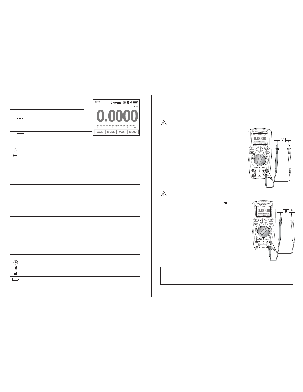
Display Symbols and Annunciators.........................................................7
Operation
AC Voltage..............................................................................................8
DC Voltage..............................................................................................8
AC + DC Voltage.....................................................................................8
mV Voltage..............................................................................................9
AC and DC Current................................................................................. 9
Frequency and Duty Cycle......................................................................10
Frequency: AC Voltage/Current Function................................................11
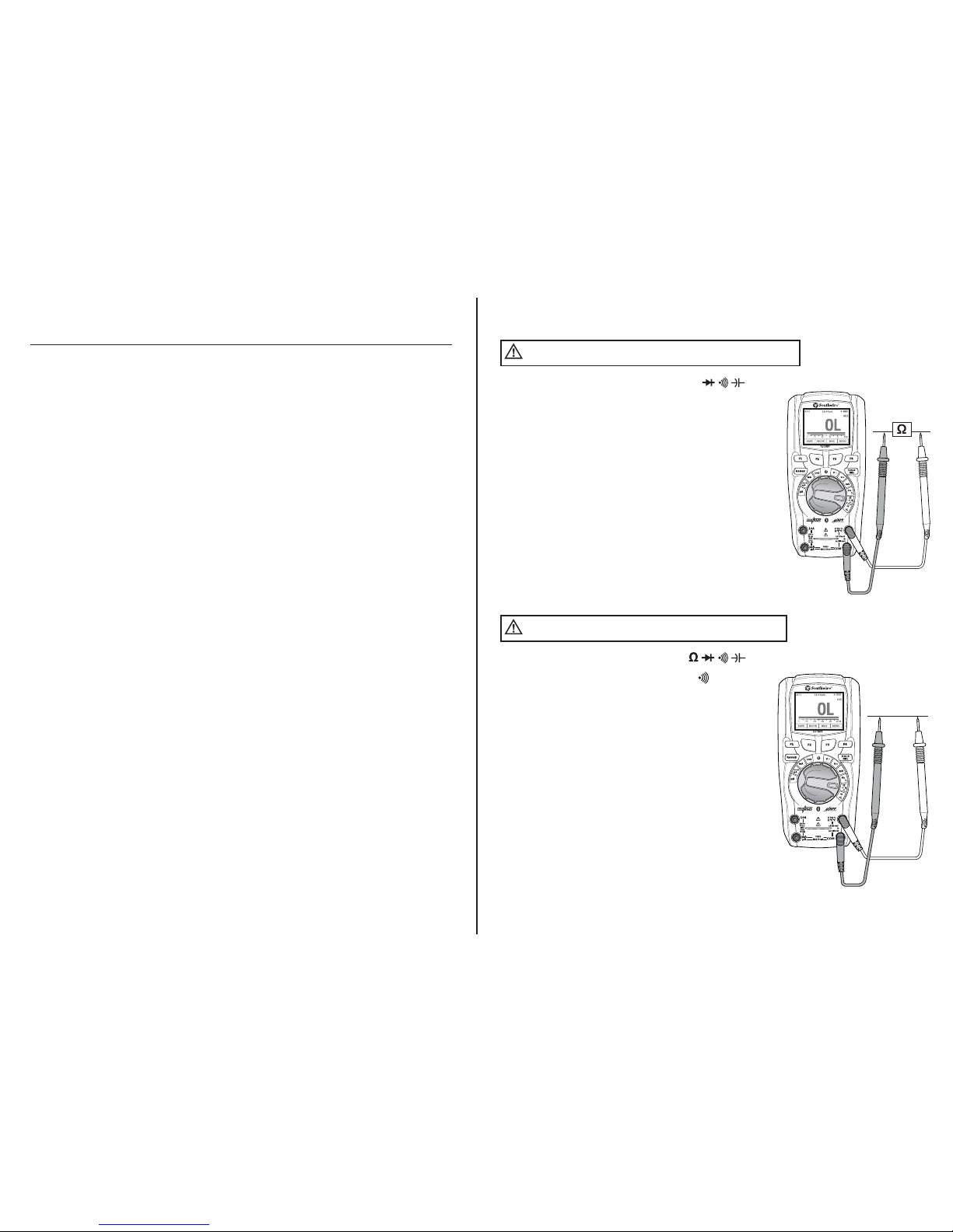
Resistance..............................................................................................12
Continuity...............................................................................................12
Capacitance...........................................................................................13
Diode Test..............................................................................................13
Temperature............................................................................................14
SAVE Function........................................................................................14
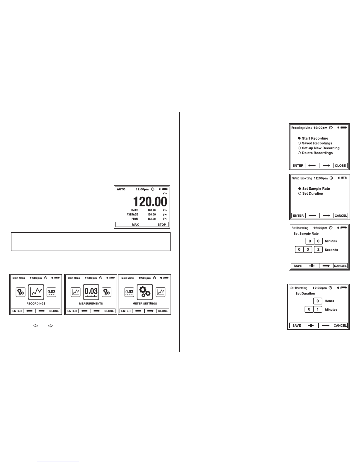
MAX/MIN/AVERAGE Mode......................................................................14
PEAK Mode.............................................................................................15
MENU Functions
RECORDINGS
Set-up New Recording.......................................................16
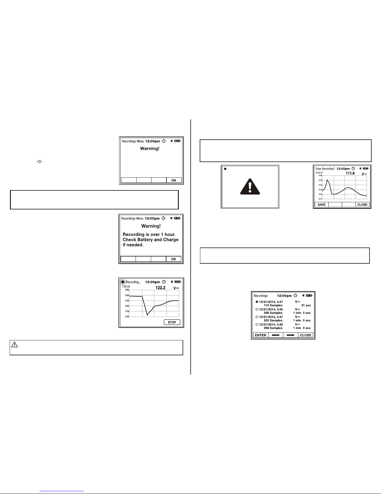
Start Recording..................................................................17
Access Saved Recordings..................................................18
Delete Recordings..............................................................20
MEASUREMENTS
Access Saved Measurements............................................21
Delete Measurements.........................................................22
METER SETTINGS
Bluetooth........................................................................... 23
APO (Auto Power Off).........................................................24
Beeper On/Off....................................................................24
Date/Time..........................................................................25
Meter Info..........................................................................27
Recharging Battery........................................................................... .......28
Accessing Battery and Changing Fuse....................................................29
Specifications.....................................................................................30
Warranty..................................................................................................32
Table of Contents
2
WARNINGS
• Read, understand and follow Safety Rules and Operating Instructions in
this manual before using this meter.
• The meter’s safety features may not protect the user if not used in accordance
to the manufacturer’s instructions.
• Ensure that the test leads are fully seated in the input jacks and keep
fingers away from the metal probe tips when taking measurements.
• Before changing functions using the selector switch, always disconnect the
test leads from the circuit under test.
• Use only UL listed test leads with the proper safety category rating.
• Comply with all applicable safety codes. Use approved personal protective
equipment when working near live electrical circuits - particularly with regard
to arc-flash potential.
• Use caution on live circuits. Voltages above 30 V AC rms, 42 V ac peak,
or 60 V dc pose a shock hazard.
• Do not use meter or test leads if they appear damaged.
• Verify operation before using meter by measuring a known live voltage.
• Do not use the meter in wet or damp environments or during electrical storms.
• Do not use the meter near explosive vapors, dust or gasses.
• Do not use the meter if it operates incorrectly. Protection may be compromised.
• Do not operate meter while Low Battery warning is on.
(Battery Indicator will flash). Recharge the battery before using.
• Do not apply voltage or current that exceeds the meter’s maximum rated
input limits.
Introduction
The Southwire 15190T MaintenancePROTM Color Screen Multimeter with
MAppTM Mobile App features a high resolution color display with graphing
capabilities, rechargeable Lithium Ion battery, rugged double molded housing,
CAT IV 600V/CAT III 1000V safety rating and an intuitive menu driven operating
system. Advanced functions include Frequency, Duty Cycle, Capacitance,
Temperature, Max/Min/Average, and Peak Hold. A recording mode with a trend
chart is provided for detailed circuit analysis. The 15190T wirelessly transmits
data to the MAppTM mobile app via Bluetooth®allowing you to view, save,
organize and share datalogs as well as take measurements from a safe distance.
Visit nextgenmeters.southwiretools.com for mobile app download information.
This meter is fully tested and calibrated and, with proper use, will provide many
years of service.

3
Function
Voltage AC/DC
µA/mA Current AC or DC
10A Current AC or DC
Frequency, Resistance,
Capacitance, Diode Test,
Continuity
Temperature
Maximum Input 15190T
1000VAC rms, 1000VDC
800mA 1000V fast acting fuse
10A 1000V fast acting fuse
(10A for 30 seconds max. every 15 minutes)
1000VAC rms, 1000VDC
General Specifications
Insulation
Diode Test
Continuity Test
PEAK
Low Battery Indication
Display
Polarity
Overrange Indication
Measurement Rate
Auto Power Off
Input Impedance
AC Response
ACV Bandwidth
Operating Temperature
Storage Temperature
Operating Humidity
Storage Humidity
Operating Altitude
Battery
Fuses
Dimensions/Weight
Safety
Input Limits
Class 2, Double insulation
Test current of 0.9mA maximum, open circuit voltage 3.2V DC typical
Audible signal will sound if the resistance is less than 30Ω(approx.)
test current <0.35mA
Captures peaks >1ms
Battery indicator will flash
TFT LCD color display
Automatic (-) negative polarity indication
“OL” is displayed
20 times per second, nominal
5 to 30 minutes (approx.) with disable
>10MΩVDC & >9MΩVAC
TrueRMS
50Hz to 20kHz
41°F to 104°F (5°C to 40°C)
-4°F to 140°F (-20°C to 60°C)
Max 80% up to 87°F (31°C) decreasing linearly to 50% at 104°F (40°C)
<80%
7000ft. (2000 meters) maximum
One 7.4 volt rechargeable Lithium Ion battery
mA, µA ranges: 800mA/1000V ceramic fast blow
10A range: 10A/1000V ceramic fast blow
6.6” x 3.1” x 2” (168 x 79 x 51mm)/0.90lb (408g)
Complies with UL 61010-1 3rd edition for measurement CAT IV 600V,
CAT lll 1000V, Pollution Degree 2
4
Potential danger. Indicates the user must refer to the manual for important safety information
Indicates hazardous voltages may be present
Equipment is protected by double or reinforced insulation
Indicates the terminal(s) so marked must not be connected to a circuit where the
voltage with respect to earth ground exceeds the maximum safety rating of the meter
Indicates the terminal(s) so marked may be subjected to hazardous voltages
MAX
1000V
International Safety Symbols
Brief Description Typical Applications
Category Rating
Single phase
receptacles and
connected loads
Three phase circuits
and single phase
lighting circuits in
commercial buildings
- Household appliances, power tools
- Outlets more than 30ft (10m) from a CAT III source
- Outlets more than 60ft (20m) from a CAT IV source
- Equipment in fixed installations such as 3-phase motors, switchgear and distribution panels
- Lighting circuits in commercial buildings
- Feeder lines in industrial plants
- Any device or branch circuit that is close to a CAT III source
CAT II
CAT III
The measurement category (CAT) rating and voltage rating is determined by a combination of the meter, test probes and any
accessories connected to the meter and test probes. The combination rating is the LOWEST of any individual component.
CAT IV
Connection point to
utility power and
outdoor conductors
- Primary distribution panels
- Overhead or underground lines to detached buildings
- Incoming service entrance from utility
- Outdoor pumps
FCC Statement
Warning: Changes or modifications to this unit not expressly approved by the Southwire Company, LLC. could void the user’s authority
to operate the equipment.
NOTE: This equipment has been tested and found to comply with the limits for a Class B digital device, pursuant to Part 15 of the
FCC Rules. These limits are designed to provide reasonable protection against harmful interference in a residential installation.
This equipment generates, uses and can radiate radio frequency energy and, if not installed and used in accordance with the
instructions, may cause harmful interference to radio communications.
However, there is no guarantee that interference will not occur in a particular installation.
If this equipment does cause harmful interference to radio or television reception, which can be determined by turning the equipment
off and on, the user is encouraged to try to correct the interference by one or more of the following measures:
• Reorient or relocate the receiving antenna.
• Increase the separation between the equipment and receiver.
• Connect the equipment into an outlet on a circuit different from that to which the receiver is connected.
• Consult the dealer or an experienced radio/TV technician for help.
The device must not be co-located or operating in conjunction with any other antenna or transmitter.
This device complies with Part 15 of the FCC Rules. Operation is subject to the following two conditions:
(1) this device may not cause harmful interference, and
(2) this device must accept any interference received, including interference that may cause undesired operation.
IC Statement
This device complies with RSS247 of Industry Canada. This device complies with Industry Canada license-exempt RSS standard(s).
Operation is subject to the following two conditions: (1) this device may not cause interference, and (2) this device must accept any
interference, including interference that may cause undesired operation of the device.
Radiation Exposure Statement:The product comply with the Canada portable RF exposure limit set
forth for an uncontrolled environment and are safe for intended operation as described in this manual.
The further RF exposure reduction can be achieved if the product can be kept as far as possible from
the user body or set the device to lower output power if such function is available.
Complies with
IDA Standards
DA107392

5
Maintenance
This Multimeter is designed to provide years of dependable service,
if the following care instructions are performed:
1. KEEP THE METER DRY. If it gets wet, wipe it off.
2. USE AND STORE THE METER IN MODERATE TEMPERATURES.
Temperature extremes can damage the battery and electronic devices and
distort or melt the plastic parts.
3. HANDLE THE METER GENTLY AND CAREFULLY. Dropping it can damage the
electronic parts or the case.
4. KEEP THE METER CLEAN. Wipe the case occasionally with a damp cloth.
DO NOT use chemicals, cleaning solvents, or detergents.
5. KEEP THE BATTERY CHARGED: Keep the battery partially charged when not in use. Charge
the battery in moderate temperatures. Temperature extremes can damage the battery.
Meter Description
1. Color display
2. F1 – F4 soft key buttons
3. RANGE button
4. HOLD/REL button
5. Rotary function switch
6. 10A input jack
7. V Hz % Ω°F°Cinput jack
8. mA/µA input jack
9. COM input jack
1.
5.
6.
3.
2.
8.
4.
7.
9.
WARNING:
Operation is limited to CAT II applications when the insulated tips are removed
from one or both test probes. Refer to Input Limits section of this manual for maximum voltage ratings.
CAT IV 600V
CAT III 1000V
CAT II
1000V
Insulated Tip On
Insulated Tip Removed
Test Leads
6
RANGE Button
The meter is in the Autoranging mode when initially tuned on. The Autorange mode
automatically selects the proper range for the measurement being made and is
generally the best mode for most applications. For measurement situations
requiring that a range be manually selected, perform the following:
1. Momentarily press the RANGE button. The “AUTO” indicator on the display
will change to “Manual”.
2. Momentarily press the RANGE button to step through the available ranges
until the desired range is selected.
3. To exit the Manual Ranging mode, press and hold the RANGE button until
the “AUTO” indicator reappears.
Soft Key Buttons (F1, F2, F3, F4)
The soft key buttons are programmed to perform multiple functions.
A description of each function is shown on the display above each button.
Momentarily press the soft key to execute the function as described on the display.
Operation
NOTE : The 15190T does not Autorrange when the Relative mode is active.
“OL”will appear on the display if the difference exceeds the range.
HOLD/REL Button
HOLD will freeze the reading on the display, momentarily press the HOLD/REL
button. The “Hold” indicator will appear on the display while the reading is being
held. Momentarily press the HOLD/REL button again to return to normal operation.
REL (relative mode) is used to zero the reading on the display and set a
reference point for subsequent readings. (Relative does not work for Duty Cycle.)
1. To activate, press and hold the HOLD/REL button until the “REL” indicator
appears on the display.
2. The meter will zero the reading and store it as a reference value.
The display will now show three readings: The main display will show the
difference between the stored Reference value and the actual measurement.
The sub-displays will show the stored Reference value and the actual value
the meter is measuring.
3. To exit the Relative mode, press and hold the HOLD/REL button until the
“AUTO” indicator appears on the display.
NOTE : Pressing the F3 soft key will restart the meter after Auto Power Off
turns the meter off.

7
Display Symbols and Annunciators
V~ AC Volts
V DC Volts
V
~
AC + DC Voltage
A~ AC Amperes
A DC Amperes
-
Display minus sign
ΩOhms
Continuity
Diode test
F Farad (capacitance)
Hz Hertz (frequency)
% Percent (duty cycle)
°F Degrees Fahrenheit
°C Degrees Celsius
n nano (10
-9
)
µ micro (10
-6
)
m milli (10
-3
)
k kilo (10
3
)
M mega (10
6
)
OL Overload
AUTO Autoranging
MAX MIN Maximum/Minimum reading
AVERAGE Average reading
PEAK Peak capture
PMAX Positive Peak on AC waveform
PMIN Negative Peak on AC waveform
HOLD Display hold
REL Relative
APO (Auto Power Off)
Bluetooth®
Beeper Indicator
Battery Charge Indicator
8
Operation
AC Voltage
1. Set the rotary function switch to the
V~ position.
2. Insert the black test lead into the COM input
jack and the red test lead into the Vinput jack.
3. Touch the test lead probes to the circuit under
test.
4. Read the voltage on the display.
DC and AC+DC Voltage Measurements
Observe all safety precautions when working on live voltages.
WARNING:
Observe all safety precautions when working on live voltages.
WARNING:
When set to AC + DC Voltage, the meter measures both the AC and DC components
to derive the effective RMS (AC + DC) value. The meter will display the AC + DC voltage
reading on the main display and the AC and DC components on the sub-displays.
The AC + DC mode is typically used when measuring voltage on unfiltered rectifier circuits.
NOTE
:
1. Set the rotary function switch to the Vposition.
2. Insert the black test lead into the COM input jack and
the red test lead into the Vinput jack.
3. Touch the test lead probes to the circuit under test.
Connect the red probe to the positive side of the circuit
and the black probe to the negative side of the circuit.
4. Read the voltage on the display.
5. To measure AC+DC voltage, press the F2 MODE soft key.
6. The meter will display the AC+DC voltage on the main
display and AC voltage and DC voltage on the sub displays.
7. Press the F2 MODE soft key to return to DC Voltage
measurements.

9
Operation cont.
mV Voltage Measurements
Observe all safety precautions when working on live voltages.
WARNING:
1. Set the rotary function switch to the mV position.
2. Use the F2 MODE soft key to select AC or DC mV.
mV~ will appear on the display for AC voltage and
mV for DC voltage.
3. Insert the black test lead into the COM input jack and
the red test lead into the Vinput jack.
4. Touch the test lead probes to the circuit under test.
For DC, connect the red probe to the positive side of
the circuit and the black probe to the negative side
of the circuit.
5. Read the voltage on the display.
1. Insert the black test lead into the COM input jack.
2. For current measurements up to 10A, set the function
switch to the 10A position and insert the red test lead
into the positive 10A input jack.
3. For mA measurements up to 500mA, set the function
switch to the mA position and insert the red test lead
into the mA µA input jack.
4. For µA measurements up to 5000µA, set the function
switch to the µA position and insert the red test lead
into the mA µA input jack.
5. Use the F2 MODE soft key button to select
AC or DC current. A~ will appear on the display for
AC current and A will appear for DC current.
AC and DC Current Measurements
Observe all safety precautions when working on live circuits.
Measurements in the 10A range should be limited to 30 seconds max. every 15 minutes.
WARNING:
10
Operation cont.
NOTES:
The 4~20mA range is used to measure current loops that are commonly
used in instrumentation and process controllers. The reading is expressed as a
percentage of the linear scale (Example: 4mA = 0%, 12mA = 50%, 20mA = 100%).
6. Remove power from the circuit under test, then open up the circuit at the point
where you want to measure current.
7. Touch the test lead probes in series with the circuit under test.
For DC measurements, touch the red probe to the positive side of the circuit
and the black probe to the negative side of the circuit.
8. Apply power to the circuit.
9. Read the current on the display.
AC and DC Current Measurements cont.
1. Set the rotary function switch to the Hz % position.
2. Insert the black test lead into the COM input jack and
the red test lead into the Hz % input jack.
3. Touch the test lead probes to the circuit under test.
4. Read the frequency on the display.
5. To measure % Duty Cycle, press the F2 MODE soft
key button.
6. The meter will display Frequency (Hz) on the main
display and Time Period (ms) and Duty Cycle (%)
on the sub displays.
7. Press the F2 MODE soft key to return to Frequency
measurements.
Frequency, % Duty Cycle Measurements
Observe all safety precautions when working on live voltages.
WARNING:

11
1. Follow the instructions for operation on AC Voltage Measurements.
2. Press the F2 MODE soft key to switch to frequency.
The “Hz” symbol will appear on the display.
3. The meter will display Frequency Hz on the main display and
Voltage (V~) and Duty Cycle (%) on sub displays.
4. The meter can be set to trigger on the negative or positive slope of the
frequency waveform. Use the F4 TRIG soft key to select a positive (+)
or negative (-) trigger. The “+” or “-“ symbol is displayed next to the
Duty Cycle (%) reading.
5. Press the F2 MODE soft key to return to AC Voltage measurements.
Measuring Frequency when in the AC Voltage Function
1. Follow the instructions for operation on AC Current Measurements.
2. Press the F2 MODE soft key to switch to frequency.
The “Hz” symbol will appear on the display.
3. The meter will display Frequency Hz on the main display and
Current (A~) and Duty Cycle (%) on sub displays.
4. The meter can be set to trigger on the negative or positive slope of the
frequency waveform. Use the F4 TRIG soft key to select a positive (+)
or negative (-) trigger. The “+” or “-“ symbol is displayed next to the
Duty Cycle (%) reading.
5. Press the F2 MODE soft key to return to AC Current measurements.
Measuring Frequency when in the AC Current Function
Operation cont.
12
1. Set the rotary function switch to the Ωposition.
The “MΩ” symbol will appear on display.
2. Insert the black test lead into the COM input jack and
the red test lead into the
Ω
input jack.
3. Touch the test lead probes to the component under test.
If the component is installed in a circuit, it is best to
disconnect one side before testing to eliminate
interference from other devices.
4. Read the resistance on the display.
Resistance Measurements
Never test resistance on a live circuit.
WARNING:
1. Set the rotary function switch to the position.
2. Press the F2 MODE soft key until the “
Ω
” symbol
appears on the display.
3. Insert the black test lead into the COM input jack and
the red test lead into the
Ω
input jack.
4. Touch the test lead probes to the device or wire
under test.
5. A beeper will sound if the resistance is
approximately 30 ohms or less and the resistance
value will be shown on the display.
Continuity Test
Never test continuity on a live circuit.
WARNING:

13
Capacitance Test
Never test capacitors on a live circuit. Safely
discharge capacitors before taking capacitance measurements.
WARNING:
NOTE:
When testing small value capacitors <50nF press the
HOLD/REL button to Zero out the offset before connecting to the
capacitor under test. The measurement will be displayed on
the main display.
1. Set the rotary function switch to the position.
2. Press the F2 MODE soft key until the “nF” symbol
appears on the display.
3. Insert the black test lead into the COM input jack and
the red test lead into the
Ω
input jack.
4. Touch the test lead probes to the capacitor under test.
5. Read the capacitance value on the display. It may take
up to a minute to get a stable reading on large
capacitors.
Diode Test
Never test diodes in a live circuit.
WARNING:
1. Set the rotary function switch to the
position.
2. Press the F2 MODE soft key until the “V” symbol
appears on the display.
3. Insert the black test lead into the COM input jack and
the red test lead into the
Ω
input jack.
4. Touch the test lead probes to the diode under test.
5. Forward voltage will indicate 0.4 to 0.7 on the display.
Reverse voltage will indicate “OL”. Shorted devices will
indicate near 0 and an open device will indicate “OL”
in both polarities.
Red Black Black Red
Probe Probe Probe Probe
Forward test Reverse test
14
1. Set the rotary function switch to the °F °C position.
2. Connect the Temperature Probe to the Banana Plug Adapter.
Note the –and +markings on the adapter. Connect the
adapter to the meter, making sure the –side is inserted
into the COM input jack and the +side is inserted into the
°F °C input jack.
3. Press the F2 MODE soft key to select readings in °F or °C.
4. Touch the tip of the Temperature Probe to the object
being measured. Maintain contact with the object until
the reading stabilizes (about 30 sec).
5. Read the temperature on the display.
Temperature Measurements
SAVE Function
The SAVE function allows a screenshot to be captured and saved in internal memory.
1. Refer to the manual for proper operation on the measuring function being used.
2. From any measurement function, press the F1 SAVE soft key to take a screenshot
of the measurement shown on the display. SAVED will momentarily appear on the
display as the measurement is being saved.
3. Refer to MENU Function to access saved measurements.
Do not touch the temperature probe to live circuits.
WARNING:
1. Refer to the manual for proper operation on
the measuring function being used.
2. From any measurement function, press the F3 MAX
soft key to start the MAX/MIN/AVERAGE mode.
The meter will display real time measurements
on the main display and the MAX, AVERAGE and
MIN readings on the sub displays.
3. Press the F4 STOP soft key to freeze the
readings on the display.
a. To take a screenshot of the frozen display and
save it in internal memory, press the F1 SAVE soft key.
After saving, the meter will start a new set of MAX/MIN/AVERAGE readings.
b. To restart without saving, press the F2 START soft key.
The meter will start a new set of MAX/MIN/AVERAGE readings.
c. Press the F4 soft key CLOSE button to exit the MAX/MIN/AVERAGE mode.
MAX/MIN/AVERAGE Mode
In the MAX/MIN/AVERAGE mode,the meter captures and displays the maximum (MAX) and
minimum (MIN) readings and calculates and displays the running AVERAGE of all readings.
If enabled, the beeper will annunciate every time a new maximum or minimum reading is displayed.

15
PEAK Mode
The PEAK mode is accessible when measuring AC Voltage or Current. In the PEAK mode, the meter
captures and displays the highest positive peak (PMAX) and the highest negative peak (PMIN) of the
AC waveform. The meter also calculates and displays the running AVERAGE of all readings. If enabled,
the beeper will annunciate every time a higher peak is displayed.
Main Menu Functions
From any measurement function, press the F4 MENU soft key to enter the Main Menu.
NOTE:
The meter does not autorange when in the PEAK mode, The meter will display OL
if the reading exceeds the range. Use the RANGE button to manually set the meter to the
proper range before entering the PEAK mode.
1. Refer to the manual for proper operation on the measuring function being used
(AC Voltage or AC Current).
2. When measuring AC Voltage or Current, press the F3 MAX soft key. PEAK will appear above
the F2 soft key.
3. Press the F2 PEAK soft key. The meter will display the real time Voltage or Current reading
on the main display and the PMAX, AVERAGE and PMIN readings on the sub displays.
4. Press the F4 STOP soft key to freeze the readings on the display.
a) To take a screenshot of the frozen display and save
it in internal memory, press the F1 SAVE soft key.
After saving, the meter will start a new set of
PMAX/PMIN/Average readings.
b) To restart without saving, press the F2 START soft
key. The meter will start a new set of
PMAX/PMIN/Average readings.
c) Press the F4 CLOSE soft key to exit the PEAK mode.
Follow steps below to select functions from the Main Menu and sub-menus.
1. Use the F2 or F3 soft key to select desired function.
2. Press the F1 ENTER soft key to access selected function.
3. Press the F4 CLOSE soft key to exit function.
Fig. 1 Fig. 2 Fig. 3
16
RECORDINGS
From the Main Menu,
select and ENTER RECORDINGS (Fig. 1).
Set-up New Recording
1. From Recordings Menu,
select and ENTER Set-up New Recording (Fig. 4).
2. Use the soft keys to select
and ENTER Set Sample Rate or Set
Duration (Fig. 5).
The Sample Rate can be set from 0.2 seconds to 19 minutes 59 seconds.
Fig. 4
Fig. 5
Fig. 6
The Recording Duration can be set from 1 minute to 9 hours 59 minutes.
Fig. 7

17
Start Recording
3. Set Sample Rate (Fig. 6) and Set Duration (Fig. 7)
following the steps below:
a) Use the F2 + soft key to set the numeric value
(highlighted in red).
b) Use the F3 soft key to advance to the next time unit.
c) Press the F1 SAVE soft key to save the settings and
return to Recordings Menu.
d) Press the F4 CANCEL soft key to return to
Recordings Menu without changing setting.
1. From the Recordings Menu,
select and ENTER Start Recording (Fig. 4).
2. Press the F4 OK soft key to start recording if battery is fully charged (Fig. 9).
3. To end the recording before the preset duration, press the F4 STOP soft key (Fig. 10).
Recording and a flashing Red dot will appear to
indicate the meter is in the recording mode.
A countdown timer located below the Recording
indicator displays the time left in the recording
session. The meter will display the actual
measurement and graph a series of readings.
Readings will update according to the sample rate.
On long recordings, a reminder will appear to
check battery before starting recording
NOTE: A warning will appear if the combination of the recording duration and sample rate
exceeds the capacity of the meter. If this warning appears, Press OK and decrease the
sample rate or decrease the recording duration. (Fig. 8)
Fig. 8
Fig. 9
Fig. 10
Use caution on live circuits. When recording, the measurement shown on
the display will only update as fast as the sample rate setting.
WARNING:
Set-up New Recording cont.
Duration/Sample Rate
Exceeds Available Memory.
Please Reduce Sample Rate
Or Duration.
18
Start Recording cont.
Access Saved Recordings
Fig. 12
Fig. 13
4. Press the F1 SAVE soft key to exit and save the recording (Fig. 12).
5. Press the F4 CLOSE soft key to exit without saving (Fig. 12).
1. From Recordings Menu (Fig. 4), select and ENTER Saved Recordings (Fig. 13).
The Save Recording screen will appear when the recording is done or when the
recording is stopped.
The recordings are listed in order from last to first: The last saved recording will appear first.
Each recording will indicate the date and time the recoding was started, the number of
recorded samples, and the measurement unit.
On long recordings, the display will turn off to conserve battery power.
A flashing Red dot and warning symbol will appear to indicate that a recording
session is in progress. Pressing any button will reactivate the display. (Fig. 11)
NOTE:
The Save Recording screen stays on for several seconds. If neither SAVE
or CLOSE is selected, the meter will automatically save and exit recording.
NOTE:
Fig. 11

19
2. Use the F2 and F3 soft keys (Fig. 13) to the select Recorded File as shown below:
3. Press the F1 soft key to OPEN Recording (Fig. 13).
6. Press the F4 CLOSE soft key to exit Saved File (Fig. 14).
The date and time the Recorded File was started is displayed above the graph. The reading
at the top of the display corresponds to the measurement point indicated by the vertical
cursor line on graph.
Fig. 14
Access Saved Recordings cont.
1st Saved File 2nd Saved File 3rd Saved File ,
F2 soft key:
Last Saved File ............…3rd Saved File 2nd Saved File
1st Saved File
F3 soft key:
4. Momentarily press the F2 or F3 soft key to move the cursor to the next measurement
point or press and hold the soft key until reaching the desired point along the graph.
The time line shown on the bottom of the graph indicates the time each measurement
was recorded relative to the start of the recording (Fig. 14).
5. For greater resolution, momentarily press the F1 ZOOM soft key (Fig. 14) to expand the
graph as shown below (the graph will expand up to 64 times depending on the number
of measurement points):
1x 2x 4x 8x 16x 32x 64x
...........................Last Saved File
20
7. Use the soft keys to DELETE recording or CANCEL and return to Saved Recordings
without deleting (Fig. 15).
Access Saved Recordings cont.
Fig. 15
1. From Recordings Menu, select and ENTER Delete Recordings (Fig. 4).
2. Press the F1 soft key to DELETE ALL RECORDINGS (Fig. 16).
3. Press the F4 soft key to CANCEL and return to Recordings Menu without deleting (Fig. 16).
Delete Recordings
Fig. 16

21
MEASUREMENTS
Fig. 17
From the Main Menu, select and ENTER MEASUREMENTS (Fig. 2).
Access Saved Measurements
1. Use the soft keys to access Saved Measurements (Fig. 17).
The measurements are listed in order from last to first: The last saved measurement will
appear first. Each measurement will indicate the measurement unit and date and time
the measurement was saved. (Fig. 18)
Fig. 18
2. Use the F2 and F3 soft keys (Fig.18) to the select Measurement File as shown below:
1st Saved File 2nd Saved File 3rd Saved File ,
F2 soft key:
F3 soft key: Last Saved File ..........…3rd Saved File 2nd Saved File
1st Saved File
3. Press the F1 soft key to OPEN the Measurement File (Fig. 18).
..........................Last Saved File
22
Access Saved Measurements cont.
Fig. 19
4. Use the F2 and F3 soft keys (Fig. 19) to select other Saved Files as shown
in Step 2.
5. Press the F1 DELETE soft key to delete Saved File (Fig. 19).
6. Press the F4 CANCEL soft key to return to Measurements without deleting (Fig. 19).
Delete Measurements
1. Use the soft keys to select and ENTER Delete Measurements (Fig. 17).
Fig. 20
2. Press the F1 DELETE soft key to delete ALL SAVED MEASUREMENTS (Fig. 20).
3. Press the F4 CANCEL soft key to return to Measurements without deleting (Fig. 20).

23
METER SETTINGS
1. From the Main Menu, select and ENTER METER SETTINGS (Fig. 3).
Fig. 21
2. Use the soft keys to select and ENTER desired setting (Fig. 21).
Bluetooth®
1. From Meter Settings, select and ENTER Bluetooth (Fig. 21).
Fig. 22
2. Use the F1 OK soft key to turn Bluetooth
®
on or off and return to Meter Settings (Fig. 22).
The symbol will appear on the display when Bluetooth
®
is on.
NOTE: Turn Bluetooth
®
off when not in use to maximize battery life.
The Bluetooth® word mark and logos are registered trademarks owned by Bluetooth SIG, Inc.
and any use of such marks by Southwire Company, LLC. is under license.
Other trademarks and trade names are those of their respective owners.
24
APO (Auto Power Off)
1. From Meter Settings, select and ENTER APO (Fig. 21).
Fig. 23
2. Use the F3 soft key to select APO or APO TIME (highlighted in red), (Fig. 23).
3. Use the F2 + soft key to turn APO ON or OFF or adjust APO timer (Max. 30 min), (Fig. 23).
4. Press the F1 OK soft key to save setting and return to Meter Settings (Fig. 23).
Beeper On/Off
1. From Meter Settings, select and ENTER Beeper (Fig. 21).
Fig. 24
2. Use the F1 OK soft key to turn the beeper on or off and return to Meter Settings (Fig. 24).
The symbol will appear on the display when the beeper is on.
NOTE: The beeper will continue to work on Continuity if the beeper is turned off.

25
Date/Time Menu
1. From Meter Settings, select and ENTER Date/Time (Fig. 21).
Fig. 25
2. Use the soft keys to select and ENTER desired Date or Time setting (Fig. 25).
Date Format
1. From the Date/Time Menu, select and ENTER Date Format (Fig. 25).
Fig. 26
2. Use the F2 and F3 soft keys to select Month/Day/Year or Day/Month/Year (Fig. 26).
3. Press the F1 OK soft key to save setting and return to Date/Time Menu (Fig. 26).
26
Set Date
1. From the Date/Time Menu, select and ENTER Set Date (Fig. 25).
Fig. 27
2. Use the F2 + soft key to set numeric value (highlighted in red), (Fig. 27).
3. Use the F3 soft key to select Month, Day or Year (Fig. 27).
4. Press the F1 OK soft key to save setting and return to Date/Time Menu (Fig. 27).
Time Format
1. From the Date/Time Menu, select and ENTER Time Format (Fig. 25).
Fig. 28
2. Use the F2 and F3 soft keys to select a 12 hour or 24 hour clock (Fig. 28).
3. Press the F1 OK soft key to save setting and return to Date/Time Menu (Fig. 28).

27
Set Time
1. From the Date/Time Menu, select and ENTER Set Time (Fig. 25).
Fig. 28
2. Use the F2 + soft key to set numeric value (highlighted in red), (Fig. 28).
3. Use the F3 soft key to select Hours or Minutes (Fig. 28).
4. Press the F1 OK soft key to save setting and return to Date/Time Menu (Fig. 28).
Meter Info
From Meter Settings, select and ENTER Meter Info (Fig. 21).
Displays user interface and firmware version (Fig. 29).
Fig. 29
28
Recharging the Battery
Technical Measures/Precautions
1. Do not short (+) or (-) battery terminals with conductors.
2. Do not open the battery module.
3. Do not expose the battery to water or humidity (avoid water condensation).
4. Do not expose to heat, solder or throw into fire.
5. Immediately disconnect the batteries if, during operation, it emits an unusual smell, develops heat,
changes shape/geometry, or behaves abnormally. Contact the manufacturer if any of these problems
are observed.
6. Keep away from children.
Environmental Protection
• Do not mix these batteries with the solid waste stream.
• When the battery reaches the end of its useful life, the spent battery should be disposed of by a
qualified recycler or hazardous materials handler. If you are unsure of how to properly dispose of this
battery, contact your local Southwire or distribution office for disposal information.
NOTE: Battery will not charge if fuse is blown. If battery charge indicator does not appear when
connecting charger, check the 800mA fuse.Refer to Page 29 in the manual for proper fuse replacement.
Charger
Rotary switch must be in off ( ) position during charging or damage to meter
may occur.
WARNING:
Use only Southwire 60155R or 60157R charger to recharge the battery.
Recharging the battery with any other charger could result in damage to the battery.
WARNING:
Charging Fully Charged
1. Turn the rotary function switch to the position.
2. Insert the charger into the meter input jacks.
3. Plug the charger into an AC outlet
(Charger will operate on AC voltage from 100 to 240V 50/60Hz).
4. The meter will display an image of a charging battery.
When the battery is fully charged,
the image will be frozen. (See illustrations below.)
Fully recharge the battery before starting a long recording.
The battery symbol will flash when the battery is too low for
reliable operation. Recharge the battery as soon as this occurs.
Fully charge the battery prior to using it for the first time.
Charging time is 4 hours, but note that charging time will vary
depending on temperature and battery condition.

29
1. Lift up tilt stand to access battery door.
2. Use small coin to unlock battery door.
3. Lift up on tab below lock to remove battery door.
4. Lift up on battery to remove.
5. Use an exact replacement when replacing
battery.
6. When replacing fuse, remove the old fuse by
gently pulling it out from its holder.
7. Install new fuse into holder.
8. Always use an exact replacement UL rated fuse of the proper size and value.
800mA/1000V (6.3 x 32mm) fast blow for the µA and mA ranges.
and 10A/1000V (10 x 38mm) fast blow for the 10A range.
Accessing Battery and Changing Fuse
To avoid electric shock, remove test leads from the meter before removing
the battery door. ONLY use an exact replacement UL rated fuse when replacing fuses.
WARNING:
To avoid electric shock, do not operate meter until the battery door is in place and
fastened securely.
WARNING:
NOTE: 800mA fuse can be accessed by carefully removing rubber cover. Reinsert cover after replacing
fuse.
When replacing battery, follow local waste management regulations for disposal
of old battery.
WARNING:
POLYMER-LI-IONBATTERY
Tilt Stand
Battery
Fuse
Cover LOCKED UNLOCKED
30
Specifications
500.00mV
5.0000V
50.000V
500.00V
1000.0V
0.01mV
0.1mV
1mV
10mV
0.1V
±(1.0% + 5)
±(1.5% + 10)
±(3.0% + 5)
±(3.5% + 10)
±(5.5% + 20
unspecified
unspecifiedunspecified
±(0.5% +5)
AC Voltage
Function
Accuracy ±(% of reading + digits)
15190T Specifications
Range Resolution 50/60Hz <1kHz <5kHz < 20kHz (1)
Input Protection: 1000V AC rms or 1000V DC AC voltage ranges are specified from 5% to 100% of range
500.00mV
5.0000V
50.000V
500.00V
1000.0V
±(0.1% + 5)
±(0.5% + 5)
±(0.1% + 5)
0.01mV
0.1mV
1mV
10mV
0.1V
DC Voltage
Function Range Resolution
Input Protection: 1000V AC rms or 1000V DC
Accuracy ±(% of reading + digits)
500.00µA
5000.0µA
50.000mA
500.00mA
10.000A
±(0.2% + 5)
±(0.3% + 8)
±(0.5% + 8)
0.01µA
0.1µA
1µA
10µA
1mA
DC Current
Function Range Resolution
Overload Protection: 800mA/1000V and 10A/1000V Fuses
Accuracy ±(% of reading + digits)
5.0000V
50.000V
500.00V
1000.0V
0.1mV
1mV
10mV
0.1V
±(1.2% + 20) ±(3.00% + 20)
AC + DC
Voltage
Function Range Resolution
Input Protection: 1000V AC rms or 1000V DC
<1kHz <5kHz
Accuracy ±(% of reading + digits)
500.00µA
5000.0µA
50.000mA
500.00mA
10.000A
0.01µA
0.1µA
1µA
10µA
1mA
± (0.8% + 5) ± (3% + 5)
AC Current
Function Range Resolution
Overload Protection: 800mA /100V and 10A/1000V Fuses
AC current ranges are specified from 5% to 100% of range
<1kHz <5kHz
Accuracy ±(% of reading + digits)

31
Specifications
500.00Ω
5.0000kΩ
50.000kΩ
500.00kΩ
5.0000MΩ
50.000MΩ
±(0.2% + 10)
±(0.2% + 5)
±(2.0% + 10)
0.01Ω
0.1Ω
1Ω
10Ω
100Ω
1kΩ
Resistance
Resistance Range Resolution
Input Protection: 1000V AC rms or 1000V DC
Accuracy ±(% of reading + digits)
-328 to 2462
-200 to 1350°C
±(1.0% + 5.4°F)
±(1.0% + 3.0°C)
0.1°F
0.1°C
Temp
(type-K)
Resistance Range Resolution
Input Protection: 1000V AC rms or 1000V DC
* Does not include error of the thermocouple probe.
* Accuracy specification assumes ambient temperature stable to ±1 °C.
Accuracy ±(% of reading + °F/°C) *
50.00Hz
500.00Hz
5.0000kHz
50.000kHz
500.00kHz
5.0000MHz
10.000MHz
Sensitivity: 2V rms min. @ 20% to 80% duty cycle and <100kHz; 5Vrms min @ 20% to 80% duty cycle and > 100kHz.
Sensitivity:2Vrms.
Pulse width: 100µs - 100ms, Frequency: 5Hz to 150kHz
0.001Hz
0.01Hz
0.1Hz
1Hz
10Hz
100Hz
1kHz
40.00Hz-10KHz
0.1 to 99.90%
0.01Hz - 0.001KHz
0.01% ± (1.2% + 2)
± (0.01% + 5)
± (0.5% reading)
Unspecified
Frequency
(electronic)
Frequency
(electrical)
Duty Cycle
Resistance Range Resolution
Input Protection: 1000V AC rms or 1000V DC
Accuracy ±(% of reading + digits)
1pF
10pF
100pF
0.001µF
0.01µF
0.1µF
1.0uF
± (1.5% + 20)
± (1.5% + 8)
± (1.0% + 8)
± (1.5% + 8)
± (1.0% + 8)
± (1.5% + 8)
± (2.5% + 20)
Capacitance
Resistance Range Resolution
Input Protection: 1000V AC rms or 1000V DC * When using the relative mode to compensate for offsets.
Accuracy ±(% of reading + digits)
5.000nF *
50.000nF *
500.00nF
5.000µF
50.00µF
500.00µF
5000µF
32
REGISTER YOUR PRODUCT
Register your product purchase at www.southwiretools.com or by scanning
the QR code on this manual. At Southwire, we are dedicated to providing you
with the best customer experience. By following a few quick steps to register,
you can experience quicker service, more efficient support, and receive
information on our future products. Simply provide your model number,
serial number, and just a few pieces of information about yourself –
it is that quick and easy.
LIMITED WARRANTY AND LIMITATION OF LIABILITY ON
SOUTHWIRE METERS & TESTERS
Southwire Company, LLC. warrants this product to be free from defects in
material and workmanship for two years from the date of purchase. This
warranty does not cover fuses, disposable batteries, or damage arising from
an
accident, neglect, misapplication, contamination, modification, improper
maintenance or repair, operation outside of specifications, or abnormal
handling of the product.
Southwire’s sole liability, and the purchaser’s exclusive
remedy, for any breach of this warranty is expressly limited to Southwire’s repair
or replacement of the product. Whether Southwire repairs or replaces the
product will be a determination that Southwire makes at its sole discretion.
SOUTHWIRE MAKES NO WARRANTY THAT THE PRODUCT WILL
BE MERCHANTABLE OR FIT FOR ANY PARTICULAR PURPOSE.
SOUTHWIRE MAKES NO OTHER WARRANTY, EXPRESSED OR
IMPLIED, OTHER THAN THE WARRANTY SPECIFICALLY SET FORTH
HEREIN.
SOUTHWIRE WILL NOT BE LIABLE FOR ANY INCIDENTAL,
CONSEQUENTIAL, INDIRECT, SPECIAL, OR PUNITIVE DAMAGES FOR
ANY BREACH OF THIS WARRANTY.
This warranty is void if this product is used for rental purposes. No product
reseller is authorized to extend any other warranty on Southwire’s behalf
relating to this product, and no such reseller warranty will be binding on
Southwire. If you have a warranty claim, or if the product needs to be
serviced during or after the warranty period set forth above, please contact
the Customer Service Department at 855-SWTOOLS (855-798-6657).
The sender is responsible for all shipping, freight, insurance, and packaging
costs associated with sending a product to Southwire. Southwire will not be
responsible for lost or damaged products returned pursuant to this warranty.
All products returned to Southwire under this warranty should be mailed to:
Southwire Company, LLC.
Attention: Tool Warranty Return
840 Old Bremen Road
Carrollton, GA 30117

2
1
Introducción............................................................................................2
Advertencias / Límites de Entrada ..........................................................2
Especificaciones Generales.....................................................................3
Símbolos de Seguridad / Calificaciones Categorías de Seguridad...........4
Mantenimiento/Descripción del Medidor ................................................5
Botones Programables (F1, F2, F3, F4) ...................................................6
Botón RANGE ........................................................................................6
Botón HOLD/REL ...................................................................................6
Símbolos y Anunciadores en la Pantalla .................................................7
Operación
Voltaje AC...............................................................................................8
Voltaje DC...............................................................................................8
Voltaje AC + DC ......................................................................................8
Voltaje mV................................................................................................9
Corriente AC y DC ..................................................................................9
Frecuencia y Ciclo de Trabajo ................................................................10
Frecuencia: Función de Voltaje y Corriente AC........................................11
Resistencia..............................................................................................12
Continuidad............................................................................................12
Capacitancia...........................................................................................13
Prueba de Diodo ....................................................................................13
Temperatura............................................................................................14
Función SAVE ........................................................................................14
Modo MAX/MIN/AVERAGE......................................................................14
Modo PEAK ...........................................................................................15
Funciones del MENÚ
GRABACIONES
Iniciar una Nueva Grabación .............................................16
Iniciar una Grabación.........................................................17
Acceso a Grabaciones Guardadas ....................................18
Borrar Grabaciones............................................................20
MEDICIONES
Acceso a Mediciones Guardadas.......................................21
Borrar Mediciones...............................................……........22
AJUSTES DEL MEDIDOR
Bluetooth...........................................................................23
APO (Apagado Automático) ...............................................24
Encendido/Apagado del Bíper............................................24
Fecha/Hora........................................................................25
Información del Medidor.....................................................27
Recargar la Batería..................................................................................28
Acceso a la Batería y Cambio de Fusibles...............................................29
Especificaciones....................................................................................30
Garantía .................................................................................................32
Tabla de Contenidos
ADVERTENCIAS
• Leer, comprender y seguir las Reglas de Seguridad e Instrucciones de Operación
en este manual antes de usar este medidor.
• Las características de seguridad del medidor pueden no proteger al usuario si no
se utiliza de acuerdo con las instrucciones del fabricante.
• Asegúrese de que los cables de prueba están completamente insertados en
las tomas de entrada y mantenga los dedos alejados de las puntas de las sondas
de metal al tomar mediciones.
• Antes de cambiar de funciones utilizando el interruptor, desconecte siempre
los cables de prueba del circuito bajo prueba.
• Utilice únicamente cables de prueba de la lista de UL con la calificación
adecuada en la categoría de seguridad.
• Cumpla con todas las normas de seguridad aplicables. Use equipo aprobado
para protección personal cuando trabaje cerca de circuitos eléctricos activos -
en particular respecto al potencial de arco eléctrico
• Tenga cuidado en circuitos activos. Los voltajes mayores de 30 V CA RMS,
42 V AC peak, o 60 V DC suponen un riesgo de descarga eléctrica.
• No utilice si los cables del probador o los cables de prueba parecen estar dañados.
• Verifique el funcionamiento del medidor midiendo tensión conocida.
• No utilice el medidor en ambientes húmedos o mojados o durante
tormentas eléctricas.
• No utilice el medidor cerca de vapores explosivos, polvo o gases.
• No utilice el medidor si funciona incorrectamente. La protección puede
verse comprometida.
• No utilice el medidor, mientras la advertencia de batería baja esté encendida
(El indicador de la batería parpadeará). Recargue la batería antes de usar.
• No aplique un voltaje que exceda los límites máximos de entrada nominal
del probador.
Introducción
El Multímetro con Pantalla de Color 15190T MaintenancePRO™ con aplicación móvil
MApp™ cuenta con una pantalla a color de alta resolución con capacidades gráficas,
batería recargable de iones de litio, robusta carcasa de doble moldeado, calificación de
seguridad CAT IV 600 V/ CAT III 1000V y un sistema operativo impulsado por un menú
intuitivo. Funciones avanzadas incluyen Frecuencia, Ciclo de Trabajo, Capacitancia,
Temperatura, Max/Min/Average, y Peak Hold. Incluye un modo de grabación con un
gráfico de tendencia para el análisis de circuitos detallado. El 15190T transmite de forma
inalámbrica los datos a la aplicación móvil MAppTM vía Bluetooth® permitiéndole ver,
guardar, organizar y compartir registros de datos, así como tomar medidas desde una
distancia segura. Visita nextgenmeters.southwiretools.com para más información sobre
como descargar las aplicaciones móviles. Este medidor está totalmente probado y
calibrado y, con el uso adecuado, le proveerá muchos años de servicio.

3
Función
Voltaje AC/DC
Corriente µA/mA AC o DC
Corriente 10A AC o DC
Frecuencia, Resistencia,
Capacitancia, Prueba de Diodo,
Continuidad
Temperatura
Entrada Maxima 15190T
1000VAC rms, 1000VDC
800mA 1000V fusible de acción rápida
10A 1000V fusible de acción rápida
(10A durante 30 segundos máx. cada 15 minutos)
1000VAC rms, 1000VDC
Especificaciones Generales
Aislamiento
Prueba de Diodo
Prueba de Continuidad
PEAK
Indicador de Batería Baja
Pantalla
Polaridad
Indicador Sobre el Rango
Intérvalo de Medición
Apagado Automático
Impedancia de Entrada
Respuesta AC
Ancho de Banda ACV
Temperatura de Funcionamiento
Temperatura de Almacenamiento
Humedad de Operación
Humedad de Almacenamiento
Altitud de Funcionamiento
Batería
Fusibles
Dimensiones / Peso
Seguridad
Límites de Entrada
Aislamiento Clase 2, Doble aislamiento
Prueba corriente 0.9mA máxima; voltaje de circuito abierto 3.2 DC típico
Emitirá una señal audible si la resistencia es menor a 30Ω(apróx.),
corriente de prueba <0.35mA
Captura picos> 1ms
El indicador de la batería parpadeará
Pantalla a color TFT LCD
Indicación de polaridad negativa (-) automática
“OL” se muestra
20 veces por segundo, nominal
5 a 30 minutos (apróx.) con desactivación
> 10M VDC y > 9MΩVAC
True rms
50Hz a 20kHz
41° a 104°F (5°C a 40°C)
-4° a 140°F (-20° a 60°C)
Máx. 80% hasta 87°F (31°C) con disminución lineal hasta 50% a 104°F (40°C)
<80%
7000 pies (2000 metros) máximo
Una batería de iones de litio de 7.4 voltios recargable
rangos mA, µA: 800mA 1000V cerámica de quemado rápido
rango 10A: 10A/1000V cerámica de quemado rápido
6.6” x 3.1” x 2” (168 x 79 x 51mm)/0.90lb (408g)
Cumple con UL 61010-1 tercera edición de medición CAT IV 600V,
1000V CAT III, Grado de contaminación 2
4
Peligro potencial. Indica que el usuario debe referirse al manual para obtener información
de seguridad importante.
Indica que puede haber voltajes peligrosos presentes.
Equipment is protected by double or reinforced insulation
El equipo está protegido por aislamiento doble o reforzado. Indica que el terminal(es) con esa
marca no debe estar conectado a un circuito donde el voltaje con contacto a tierra exceda la
clasificación máxima de seguridad del metro.
Indica que el terminal(es) con esa marca puede ser sometido a tensiones peligrosas.
MAX
1000V
Símbolos de Seguridad Internacional
Breve descripción Aplicaciones Típicas
Calificación de
Categoría
Receptáculos monofásicos
y cargas conectadas
Tres circuitos de fase y
circuitos de iluminación
monofásicos en edificios
comerciales
– Electrodomésticos, herramientas eléctricas
– Salidas de más de 30 pies (10m) de una fuente Cat III
– Salidas de más de 60 pies (20m) de una fuente Cat IV
– El equipo en instalaciones fijas como motores de 3 fases,
interruptores y paneles de distribución
– Los circuitos de iluminación en edificios comerciales
– Líneas de alimentación en plantas industriales
– Cualquier dispositivo o circuito derivado que está cerca de una fuente de Cat III
CAT II
CAT III
La calificación de medición (CAT) y la calificación de voltaje están determinadas por una combinación del metro, sondas de prueba y los
accesorios conectados a las sondas del medidor y los cables de prueba. La calificación combinada es la más BAJA de cualquier componente individual.
CAT IV
Punto de conexión
a la red eléctrica y los
conductores al aire libre
– Paneles de distribución primaria
– Líneas aéreas o subterráneas en edificios separados
– Entrada de un servicio entrante de utilidad
– Bombas al aire libre
Declaración de la FCC
Advertencia: Los cambios o modificaciones a esta unidad no aprobados expresamente por la Compañía Southwire, LLC. podrían
anular la autoridad del usuario para operar el equipo.
NOTA: Este equipo ha sido probado y cumple con los límites para un dispositivo digital de Clase B, de acuerdo con la Parte 15 de las
Reglas de FCC. Estos límites están diseñados para proporcionar una protección razonable contra interferencias perjudiciales en una
instalación residencial. Este equipo genera, utiliza y puede irradiar energía de radiofrecuencia y, si no se instala y utiliza de acuerdo
con las instrucciones, puede causar interferencias perjudiciales en las comunicaciones de radio. Sin embargo, no hay garantía de que
no se produzcan interferencias en una instalación particular. Si este equipo causa interferencias perjudiciales en la recepción de radio
o televisión, lo cual puede comprobarse encendiendo y apagando el equipo, se recomienda que el usuario trate de corregir la
interferencia mediante una o más de las siguientes medidas:
• Reorientar o reubicar la antena receptora.
• Aumentar la separación entre el equipo y el receptor del equipo.
• Conectar el equipo a una toma eléctrica distinta de aquella a la que está conectado el receptor.
• Consultar al distribuidor o un técnico de radio y televisión para obtener ayuda.
El dispositivo no debe ubicarse ni utilizarse junto con ninguna otra antena o transmisor.
Este dispositivo cumple con la Parte 15 de las Reglas de FCC. La operación está sujeta a las dos condiciones siguientes:
(1) este dispositivo no puede causar interferencias perjudiciales y
(2) este dispositivo debe aceptar cualquier interferencia recibida, incluyendo interferencias que puedan causar un funcionamiento
no deseado.
Declaración de IC
Este dispositivo cumple con RSS247 de Industry Canada. Este dispositivo cumple con los estándares RSS exentos de licencia de
Industry Canada. La operación está sujeta a las dos condiciones siguientes: (1) este dispositivo no puede causar interferencias,
y (2) este dispositivo debe aceptar cualquier interferencia, incluidas las interferencias que puedan causar un funcionamiento no
deseado del dispositivo.
Declaración sobre la Exposición a la Radiación: El producto cumple con los límites de exposición RF
portátil de Canadá establecido para entornos no controlados y son seguros para la operación que se
describe en este manual. La reducción adicional a la exposición RF se puede lograr si el producto se
mantiene lo más lejos posible del cuerpo del usuario o al configurar el dispositivo para reducir la
potencia de salida si dicha función está disponible.
Cumple con las
Normas de IDA
DA107392

5
Mantenimiento
Este multímetro está diseñado para proveer muchos años de servicio confiable,
si se llevan a cabo las siguientes instrucciones de cuidado:
1. MANTENGA SECO EL PROBADOR. Si se moja, límpielo.
2. USE Y GUARDE EL PROBADOR EN TEMPERATURAS NORMALES. Las temperaturas extremas
pueden acortar la vida de las piezas electrónicas y distorsionar o fundir las piezas de plástico.
3. MANEJE EL PROBADOR CON DELICADEZA Y CUIDADO.
El dejarlo caer puede dañar las piezas electrónicas o la carcasa.
4. MANTENGA EL PROBADOR LIMPIO. Ocasionalmente limpie la carcasa con un paño húmedo.
NO use químicos, solventes de limpieza ni detergentes.
5. MANTENGA LA BATERÍA CARGADA: Mantenga la batería cargada parcialmente cuando no se
utiliza. Cargue la batería a temperaturas moderadas. Las temperaturas extremas pueden
dañar la batería.
Descripción del Medidor
1. Pantalla a color
2. Botones de teclas programables F1-F4
3. Botón RANGE
4. Botón HOLD/REL
5. Interruptor de función rotativa
6. Toma de entrada 10A
7. Toma de entrada V Hz% Ω °F °C
8. Toma de entrada mA/µA
9. Toma de entrada COM
1.
5.
6.
3.
2.
8.
4.
7.
9.
CAT IV 600V
CAT III 1000V
CAT II
1000V
Cables de Prueba
ADVERTENCIA
:
El funcionamiento está limitado a aplicaciones CAT II cuando se retiran las puntas aisladas
de una o ambos sondas de prueba. Consulte la sección Límites de Entrada de este manual para valores máximos de voltaje.
Punta Aislada Encendia
Punta Aislada Retirada
6
Botón RANGE
El medidor está en el modo de Rango Automático cuando se sintoniza inicialmente.
El modo de Rango Automático selecciona automáticamente el rango adecuado para la
medición que se está realizando y generalmente es el mejor modo para la mayoría de las
aplicaciones. Para situaciones en que la medida requiere que un rango sea seleccionado
manualmente, realice lo siguiente:
1. Presione momentáneamente el botón RANGE. El indicador "AUTO" en la pantalla
cambiará a "Manual".
2. Presione momentáneamente el botón RANGE para pasar por las escalas disponibles hasta
seleccionar el rango deseado.
3. Para salir del modo de rango manual, presione y sostenga el botón RANGE hasta que el
indicador "AUTO" vuelva a aparecer.
Botones de las Teclas Programables (F1, F2, F3, F4)
Los botones programables están programados para realizar múltiples funciones.
Una descripción de cada función se muestra en la pantalla por encima de cada botón.
Presione momentáneamente la tecla de función para ejecutar la función como se
describe en la pantalla.
Operación
NOTA: El 15190T no hace el Rango Automático cuando el modo Relativo está activo.
"OL" aparecerá en la pantalla si la diferencia supera el rango.
Botón HOLD/REL
HOLD congelará la lectura en la pantalla, presione momentáneamente el botón HOLD/REL.
El indicador "Hold" aparecerá en la pantalla mientras se sostiene la lectura.
Pulse momentáneamente el botón HOLD/REL de nuevo para volver al funcionamiento normal.
REL (modo relativo) se utiliza para poner a cero la lectura en la pantalla y establecer un punto
de referencia para las lecturas subsiguientes. (Relativo no funciona para el Ciclo de Trabajo.)
1. Para activar, presione y sostenga el botón HOLD/REL hasta que aparezca el indicador
"REL" en la pantalla.
2. El medidor acercará a cero la lectura y la almacenará como un valor de referencia. La pantalla
mostrará ahora tres lecturas: La pantalla principal mostrará la diferencia entre el valor de
referencia almacenado y la medición real. Los sub-pantallas mostrarán el valor de referencia
almacenado y el valor real que el medidor está midiendo.
3. Para salir del modo Relativo, presione y sostenga el botón HOLD/REL hasta que aparezca
el indicador "AUTO" en la pantalla.
NOTA : Al pulsar el botón de función F3 se reiniciará el medidor después de que
el apagado automático apague el medidor.
Table of contents
Languages:
Other Southwire Multimeter manuals

Southwire
Southwire 11050N User manual

Southwire
Southwire 10040n User manual

Southwire
Southwire 16030A User manual

Southwire
Southwire 10020N User manual

Southwire
Southwire 10030S User manual

Southwire
Southwire 13050S User manual

Southwire
Southwire 32886963360 User manual

Southwire
Southwire 10040n User manual

Southwire
Southwire 11060S User manual

Southwire
Southwire 14070T User manual