Southwire 10040n User manual

Operating Instructions
10040N AUTORANGING MULTIMETER
Multímetro de Rango Automático 10040N
Instrucciones de uso
Contents Made in China
Product distributed by Southwire Company, LLC
One Southwire Drive, Carrollton, GA 30119
©2014 Southwire Company, LLC. All rights reserved.
southwiretools.com
1-855-SW-T00LS
Toll Free Technical Help
Línea de Ayuda Técnica Gratuita
Scan for warranty informaon
and to access our mobile site.
Escanea para información de garana
y acceso a nuestro sio móvil.
2/15 Rev. 1
10040N manual
Auto
Power
Off
MODE RANGE
HOLD
REL
COM
10A
For
30sec.
MAX
every
15 min
FUSED
! !
CAT III 600V

Introduction
WARNINGS
1
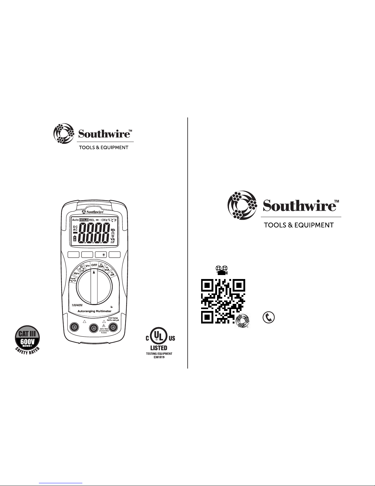
The Southwire 10040N multimeter measures AC and DC voltage and
current, resistance, capacitance, frequency, duty cycle and tempera-
ture. It also tests continuity, diodes, and has a built-in non-contact
AC voltage detector. Readings are displayed on a large backlit LCD.
This meter is fully tested and calibrated and, with proper use, will
provide many years of reliable service.
• Read, understand and follow the Safety Rules and Operating
Instructions in this manual before using this meter.
• The meter’s safety features may not protect the user if not
used in accordance to the manufacturer’s instructions.
• Ensure that the test leads are fully seated in the input jacks and
keep fingers away from the metal probe tips when taking
measurements.
• Before changing functions using the rotary function switch,
always disconnect the test leads from the circuit under test.
• Use only UL listed test leads with the proper safety category rating.
• Comply with all safety codes. Use approved personal protective
equipment when working near live electrical circuits - particularly
with regard to arc-flash potential.
• Use caution on live circuits. Voltages above 30 V AC RMS, 42 V
AC peak, or 60 V DC pose a shock hazard.
• Do not use meter or test leads if they appear damaged.
• Do not use the meter if it operates incorrectly. Protection may
be compromised.
• Verify meter’s operation by measuring a known voltage.
• Do not use the meter in wet or damp environments or during
electrical storms.
• Do not use the meter near explosive vapors, dust or gasses.
• Do not use the meter if it operates incorrectly. Protection may
be compromised.
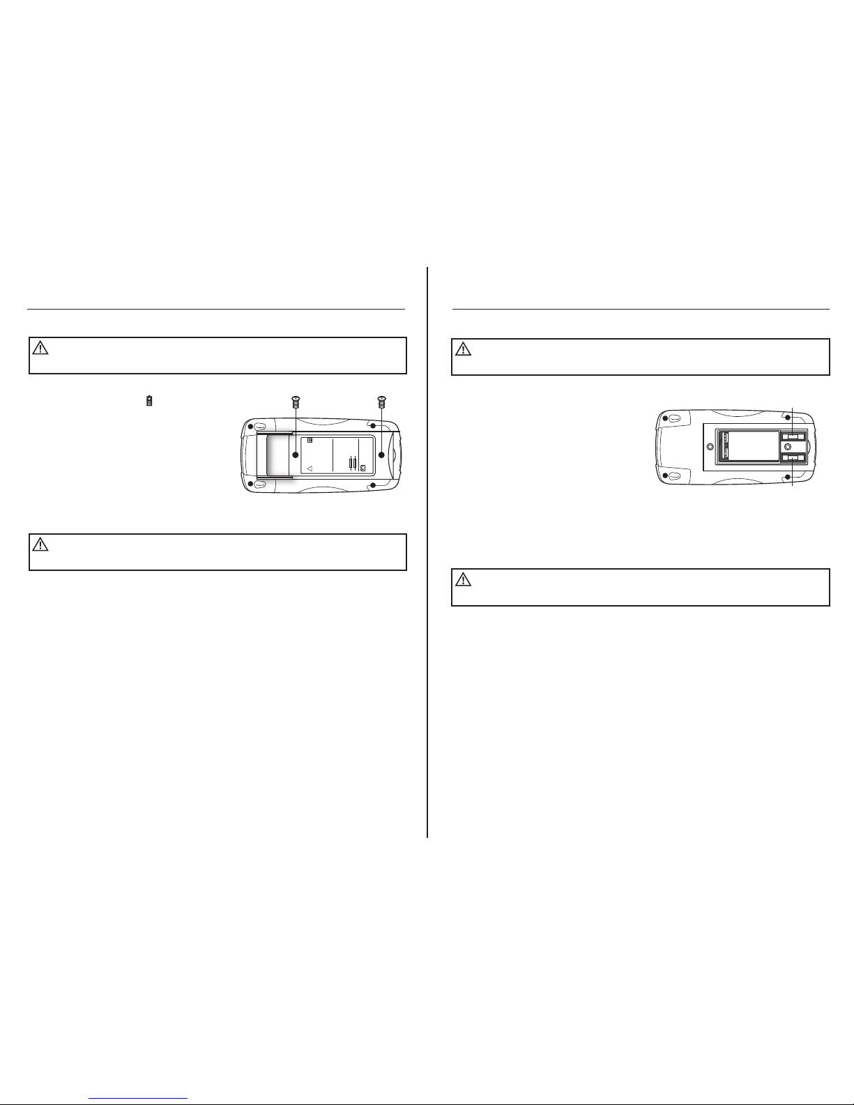
• Replace the battery as soon as the low battery warning appears.
2
Input Limits
Function Maximum Input
Voltage AC or DC
µA/mA AC or DC
10A AC or DC
Resistance, Continuity, Diode
Test, Frequency, Duty Cycle
Temperature
600V
400mA, 250V
10A AC or DC (30 seconds max every
15 minutes), 250V
250V
250V
General Specifications
Insulation
Overvoltage Category
Display
Polarity
Continuity
Overrange
Low Battery Indication
Measurement Rate
Auto Power Off
Operating Environment
Storage Temperature
Operating Altitude
Pollution Degree
Battery
Dimensions:
Weight
Safety
Class2, Double insulation
CAT III 600V
4000 counts LCD display with function indication
Automatic, (-) negative polarity indication.
Audible indication if the resistance is approximately 30Ωor less
“OL” mark indication.
The “ ” symbol is displayed when the battery voltage
drops below the operating level.
2 times per second, nominal.
Meter automatically shuts down after approx. 15 minutes of inactivity.
32° to 104°F (0°C to 40°C) at < 80 % relative humidity.
14° to 140°F (-10° to 60°C) at < 80 % relative humidity.
7000ft (2000m)
2
One 9V battery, NEDA 1604, IEC 6F22
5.4” x 2.7” x 1.5” (138 x 68 x 37mm)
0.46lb (210g)
For indoor use and in accordance with Overvoltage Category III,
Pollution Degree 2. Conforms to UL 61010-1 v.2
• Do not apply voltage or current that exceeds the meter’s
maximum rated input limit.

3
International Safety Symbols
Potential danger. Indicates the user must refer to the
manual for important safety information
Indicates hazardous voltages may be present
Equipment is protected by double or reinforced insulation
Indicates the terminal(s) so marked must not be connected
to a circuit where the voltage with respect to earth ground
exceeds the maximum safety rating of the meter
Indicates the terminal(s) so marked may be
subjected to hazardous voltages.
MAX
600V
Brief Description
Typical Applications
Category
Rating
Single phase receptacles
and connected loads
Three phase circuits and
single phase lighting
circuits in commercial
buildings
- Household appliances, power tools
- Outlets more than 30ft (10m) from a CAT III source
- Outlets more than 60ft (20m) from a CAT IV source
- Equipment in fixed installations such as 3-phase
motors, switchgear and distribution panels
- Lighting circuits in commercial buildings
- Feeder lines in industrial plants
- Any device or branch circuit that is close to a CAT III source
CAT II
CAT III
Safety Category Ratings
The measurement category (CAT) rating and voltage rating is determined by a combination of the meter,
test probes and any accessories connected to the meter and test probes.
The combination rating is the LOWEST of any individual component.
WARNING:
Operation is limited to CAT II applications when the insulated tips are removed
from one or both test probes. Refer to Input Limits section of this manual for maximum voltage ratings.
CAT III 1000V
CAT IV 600V
CAT II
1000V
Insulated Tip On
Insulated Tip Removed
4
Maintenance
This Multimeter is designed to provide years of dependable service,
if the following care instructions are performed:
1. KEEP THE METER DRY. If it gets wet, wipe it off.
2. USE AND STORE THE METER IN NORMAL TEMPERATURES. Temperature
extremes can shorten the life of the electronic parts and distort or melt
plastic parts.
3. HANDLE THE METER GENTLY AND CAREFULLY. Dropping it can damage the
electronic parts or the case.
4. KEEP THE METER CLEAN. Wipe the case occasionally with a damp cloth.
DO NOT use chemicals, cleaning solvents, or detergents.
5. USE ONLY FRESH BATTERIES OF THE RECOMMENDED SIZE AND TYPE.
Remove old or weak batteries so they do not leak and damage the unit.
6. IF THE METER IS TO BE STORED FOR A LONG PERIOD OF TIME, the batteries
should be removed to prevent damage to the unit.
Meter Description
1. LCD display
2. Rotary function switch
3. 10A (positive) input jack
4. COM (negative) input jack
5. V/Ω/ /CAP/Hz/Temp
(positive) input jack
6. MODE button
7. RANGE button
8. HOLD button
9. Relative button
10. Non-Contact Voltage Detector
indicator LED
1.
6.
7.
3.
4.
9.
8.
10.
5.
2.
CAT III 600V

5
Operation
MODE Button
To select Hz/% Duty Cycle, Ω/Diode Test/Continuity/Capacitance, AC/DC Voltage,
AC/DC Current
When the meter is first turned on, it goes into the Autoranging mode. This
automatically selects the best range for the measurements being made and is
generally the best mode for most applications. For measurement situations
requiring that a range be manually selected, perform the following:
1. Press the RANGE button. The “AUTO” display indicator will turn off.
2. Press the RANGE button to step through the available ranges until you select
the range you want.
3. Press and hold the RANGE button for 2 seconds to exit the Manual Ranging
mode and return to Autoranging.
The relative function allows you to make continuous measurements relative to
a stored reference value. A reference voltage, current, etc. can be stored and
measurements made in comparison to that value. The displayed value is the
difference between the reference value and the measured value. (Relative does
not work on Frequency or Duty Cycle).
1. Perform any measurement as described in the operating instructions.
2. Press the REL button to store the reading on the LCD display. The "REL"
indicator will appear on the LCD display.
HOLD Button
To freeze the reading on the LCD display, momentarily press the HOLD
button. The HOLD indicator will appear on the LCD display. Momentarily press
the HOLD button again to return to normal operation.
Backlight Button
The backlight illuminates the display when the ambient light is too low to permit
viewing of the displayed readings. To turn on the backlight, press the HOLD
button for > 1 second. The HOLD feature will activate when the backlight is
turned on. Momentarily, press the HOLD to exit HOLD. To turn the backlight
off, press the HOLD button for > 1 second. The HOLD feature will activate
when the backlight is turned off. Momentarily, press the HOLD to exit HOLD.
REL Button
NOTE: The RANGE button does not operate in Capacitance, Frequency or Duty
Cycle functions.
RANGE Button
6
Operation
REL Button cont.
3. The display will now indicate the difference between the stored value and
the measured value.
4. Press the REL button to return to normal operation.
VVolts
AAmps
Alternating Current
Direct Current
- Display minus sign
ΩOhms
Continuity
Diode test
F Farad (capacitance)
Hz Hertz (frequency)
%Percent (duty cycle)
ºF Degrees Fahrenheit
ºC Degrees Centigrade
AUTO Autoranging
HOLD Display Hold
REL Relative
Low battery
n nano (10-9)
µ micro (10-6)
m milli (10-3)
k kilo (103)
M mega (106)
OL Overload
Symbols and Annunciators
CAT III 600V

Auto
Power
Off
MODE RANGE
HOLD
REL
COM
10A
For
30sec.
MAX
every
15 min
FUSED
! !
7
Operation
AC and DC Voltage Measurements
Observe all safety precautions when working on live voltages.
WARNING:
1. Set the rotary function switch to the
V position.
2. Momentarily press the MODE button to
select AC or DC voltage. “AC” or “DC”
will appear on the LCD display.
3. Insert the black test lead into the
negative COM input jack and the red
test lead into the positive V input jack.
4. Touch the test probe tips in parallel to
the circuit under test. For DC
measurements, touch the red test probe
to the positive side of the circuit and the
black test probe to the negative side of
the circuit.
5. Read the voltage on the LCD display.
V
CAT III 600V
A
LOAD
8
Operation
AC and DC Current Measurements
1. Insert the black test lead into the
negative COM input jack.
2. For current measurements up to
10A, set the rotary function switch
to the 10A position and insert the red
test lead into the positive 10A input jack.
3. For current measurements up to
400mA, set the rotary function switch
to the mA position and insert the red
test lead into the positive mA input jack.
4. For current measurements up to
4000µA, set the rotary function switch
to the µA position and insert the red
test lead into the positive µA input jack.
5. Momentarily press the MODE button
to select AC or DC current. “AC” or
“DC” will appear on the LCD display.
6. Remove power from the circuit under
test, then open up the circuit at the
point where you wish to measure current.
7. Touch the test probe tips in series with
the circuit being tested. For DC
measurements, touch the red test probe
to the positive side of the circuit
and the black test probe to the negative
side of the circuit.
8. Apply power to the circuit.
9. Read the current on the LCD display.
Observe all safety precautions when working on live circuits.
Do not measure current on circuits that exceed 250V. Measurements in the 10A range
should be limited to 30 seconds maximum every 15 minutes.
WARNING:
Auto
Power
Off
MODE RANGE
HOLD
REL
COM
10A
For
30sec.
MAX
every
15 min
FUSED
! !
CAT III 600V

Auto
Power
Off
MODE RANGE
HOLD
REL
COM
10A
For
30sec.
MAX
every
15 min
FUSED
! !
9
Operation
Resistance Measurements
1. Set the rotary function switch to
the ΩCAP position.
2. Press the MODE button until “MΩ”
appears on the LCD display.
3. Insert the black test lead into the negative
COM input jack. Insert the red test lead
into the positive Ωinput jack.
4. Touch the test probe tips across the
circuit or component under test. It is
best to disconnect one side of the
device under test so the rest of the
circuit will not interfere with the
resistance reading.
5. Read the resistance on the LCD display.
Never test resistance on a live circuit.
WARNING:
Continuity Test
1. Set the rotary function switch to
the ΩCAP position.
2. Press the MODE button until “ ”
appears on the LCD display.
3. Insert the black test lead into the negative
COM input jack. Insert the red test lead
into the positive Ωinput jack.
4. Touch the test probe tips to the circuit
or wire you wish to check.
5. If the resistance is approximately 30Ω
or less, an audible tone will sound. If
the circuit is above 400Ω, the LCD
display will indicate “OL”. The resistance
will be shown on the display if it is
below 400Ω.
Never test continuity on a live circuit.
WARNING:
Ohms
Auto
Power
Off
MODE RANGE
HOLD
REL
COM
10A
For
30sec.
MAX
every
15 min
FUSED
! !
WIRE
CAT III 600V
CAT III 600V
10
Red
Probe
FORWARD TEST REVERSE TEST
Red
Probe
Black
Probe Black
Probe
Operation
Diode Test
1. Set the rotary function switch to
the ΩCAP position.
2. Press the MODE button until “ ”
appears on the LCD display.
3. Insert the black test lead into the negative
COM input jack. Insert the red test lead
into the positive Ωinput jack.
4. Touch the test probes to the diode under
test. Forward voltage will indicate 0.4 to
0.7V. Reverse voltage will indicate “OL”.
Shorted devices will indicate near 0mV
and an open device will indicate “OL” in
both polarities.
Never test diodes in a live circuit.
WARNING:
Capacitance Measurements
1. Set the rotary function switch to
the ΩCAP position.
2. Press the MODE button until “nF”
appears on the LCD display.
3. Insert the black test lead into the negative
COM input jack. Insert the red test lead
into the positive Ωinput jack.
4. Touch the test leads to the capacitor
to be tested.
5. Read the capacitance value on the LCD
display. The meter will automatically
adjust ranges between nF and µF. Large
capacitors may take up to a minute to
get a stable reading.
Safely discharge capacitors before taking capacitance
measurements.
WARNING:
Auto
Power
Off
MODE RANGE
HOLD
REL
COM
10A
For
30sec.
MAX
every
15 min
FUSED
! !
CAT III 600V

11
Operation
Frequency and % Duty Cycle Measurements
1. Set the rotary function switch to the
Hz% position.
2. Insert the black test lead into the
negative COM input jack and the red
test lead into the positive Hz% input
jack.
3. Press the MODE button to select
frequency or duty cycle. “Hz” or “%”
will appear on the LCD display.
4. Touch the test probe tips to the circuit
under test.
5. Read the frequency or % duty cycle on
the LCD display.
Temperature Measurements
1. Set the rotary function switch to the
Temp °C °F position.
2. Connect the Temperature Probe to the
Banana Plug Adapter. Insert the adapter
into the negative COM and the positive
Temp input jacks, making sure to
observe the correct polarity.
3. Touch the tip of the Temperature Probe
to the part you wish to measure. Keep
the probe touching the part under test
until the reading stabilizes (about 30 seconds).
4. Read the temperature on the LCD display.
NOTE: The meter is set to Fahrenheit.
If readings need to be in Centigrade, follow these instructions:
Observe all safety
precautions when working on live voltages.
WARNING:
To avoid electric shock, do
not let the temperature probe contact live circuits.
WARNING:
Auto
Power
Off
MODE RANGE
HOLD
REL
COM
10A
For
30sec.
MAX
every
15 min
FUSED
! !
K-T Y PE
Hz
Auto
Power
Off
MODE RANGE
HOLD
REL
COM
10A
For
30sec.
MAX
every
15 min
FUSED
! !
CAT III 600V
CAT III 600V
12
Operation
Temperature Measurements cont.
1. Refer to Battery Replacement
instructions in manual on how to
safely remove and replace
battery door.
2. Remove battery. Refer to drawing
for location of switch.
Non-Contact AC Voltage Detector (range 100 to 600V AC)
1. Non-contact voltage operates when
the function switch is in any position
except OFF. The detector does not
operate after Auto Power Off turns
the meter off.
2. Hold the meter close to the AC voltage.
3. If AC voltage within the specified
range is present, the detector light
will illuminate.
NOTE: Insulation type and thickness,
and distance from the voltage source
and other factors may effect operation.
Use other methods to verify live voltage
if there is any uncertainty.
NOTE: The detector is designed with
high sensitivity. Static electricity or other
sources of energy may randomly trip the
sensor. This is normal operation.
NOTE: The non-contact voltage detector simply detects the presence of voltage -
it will not measure and display the voltage on the LCD screen
Risk of Electrocution. Before use, always test the Voltage
Detector on a known live circuit to verify proper operation
WARNING:
SWITCH
Auto
Power
Off
MODE RANGE
HOLD
REL
COM
10A
For
30sec.
MAX
every
15 min
FUSED
!!

13
Operation
Replacing the Battery
1. When the battery drops below the
operating voltage, the symbol
will appear on LCD display. The battery
should be replaced immediately.
2. Remove the two Phillips screws from
the battery/fuse door located on the
back of the meter.
3. Remove door.
4. Replace battery with a fresh 9V battery.
5. Install the battery door and tighten the
screws.
To avoid electric shock, remove test leads from the meter
before removing the battery door.
WARNING:
To avoid electric shock, do not operate your meter until the
battery door is in place and fastened securely.
WARNING:
!
WARNING
TO AVOID ELECTRICAL
SHOCK, REMOVE ALL
INPUTS BEFORE
OPENING THE CASE.
TO PREVENT FIRE, INSTALL
FUSE WITH AMP/VOLT
RATING SHOWN:
F200mA/250V
F10A/250V
9V BATTERY
NEDA 1604 IEC 6F22
14
Operation
Replacing the Fuses
1. Remove the two Phillips screws from
the battery/fuse door located on the
back of the meter.
2. Remove door.
3. Remove the old fuse from its holder by
gently pulling it out.
4. Install the new fuse into the holder.
5. Always use a fuse of the proper size
and value (UL rated 500mA/600V fast blow
for the 400mA range, UL rated 10A/600V
fast blow for the 10A range).
6. Install battery/fuse door and tighten
screws.
To avoid electric shock, remove test leads from the meter
before removing the fuse door.
WARNING:
To avoid electric shock, do not operate your meter until the
fuse door is in place and fastened securely.
WARNING:
9V BATTERY
FUSE
FUSE

15
Specifications
Function Range Resolution Accuracy (% of reading)
AC Voltage
4.000V 1mV
40.00V 10mV
400.0V 100mV
600V 1V
Input impedance: 7.8MΩ
Frequency range: 50 to 400Hz
±1.2% ± 3 digits
±1.5% ± 3 digits
±1.5% ± 3 digits
±2.0% ± 4 digits
DC Voltage 400.0mV 0.1mV
4.000V 1mV
40.00V 10mV
400.0V 100mV
600V 1V
Input impedance: 7.8MΩ
±0.5% ± 2 digits
±1.2% ± 2 digits
±1.5% ± 2 digits
AC Current 400.0uA 0.1uA
4000uA 1uA
40.00mA 10uA
400.0mA 100uA
10A 10mA
Frequency range: 50 to 400 Hz
±1.5% ± 5 digits
±1.8% ± 5 digits
±3.0% ± 7 digits
DC Current 400.0uA 0.1uA
4000uA 1uA
40.00mA 10uA
400.0mA 100uA
10A 10mA
Frequency range: 50 to 400 Hz
±1.0% ± 3 digits
±1.5% ± 3 digits
±2.5% ± 5 digits
16
Specifications
Function Range Resolution Accuracy (% of reading)
Resistance 400.0Ω0.1Ω
4.000kΩ1Ω
40.00kΩ10Ω
400.0kΩ100Ω
4.000MΩ1kΩ
40.00MΩ10kΩ
±1.2% ± 4 digits
±1.0% ± 2 digits
±1.2% ± 2 digits
±2.0% ± 3 digits
Capacitance 40.00nF 10pF
400.0nF 0.1nF
4.000uF 1nF
40.00uF 10nF
100.0uF 0.1uF
±5.0% ± 7 digits
±3.0% ± 5 digits
±5.0% ± 5 digits
Frequency 5.000Hz 0.001Hz
50.00Hz 0.01Hz
500.0Hz 0.1Hz
5.000kHz 1Hz
50.00kHz 10Hz
500.0kHz 100Hz
5.000MHz 1kHz
10MHz 10kHz
Sensitivity: >8V RMS
±1.5% ± 5 digits
±1.2% ±3 digits
±1.5% ± 4 digits
Duty Cycle 0.1 to 99.9 0.1%
Pulse width: >100us, <100ms;
Frequency width: 5Hz – 150kHz
Sensitivity: >8V RMS
±1.2% ± 2 digits
Temperature
(Type K)
NOTE: Accuracy is stated at 65°F to 83°F (18°C to 28°C) and less than 70% RH.
-20°C~760°C 0.1°C
-4°F~1400°F 0.1°F
±3% ± 9°F/5°C

17
REGISTER YOUR PRODUCT
Register your product purchase at www.southwiretools.com or by scanning
the QR code on this manual. At Southwire, we are dedicated to providing you
with the best customer experience. By following a few quick steps to register,
you can experience quicker service, more efficient support, and receive
information on our future products. Simply provide your model number,
serial number, and just a few pieces of information about yourself –
it is that quick and easy.
LIMITED WARRANTY AND LIMITATION OF LIABILITY ON
SOUTHWIRE METERS & TESTERS
Southwire Company, LLC warrants this product to be free from defects in
material and workmanship for two years from the date of purchase. This
warranty does not cover fuses, disposable batteries, or damage arising from
an
accident, neglect, misapplication, contamination, modification, improper
maintenance or repair, operation outside of specifications, or abnormal
handling of the product.
Southwire’s sole liability, and the purchaser’s exclusive
remedy, for any breach of this warranty is expressly limited to Southwire’s repair
or replacement of the product. Whether Southwire repairs or replaces the
product will be a determination that Southwire makes at its sole discretion.
SOUTHWIRE MAKES NO WARRANTY THAT THE PRODUCT WILL
BE MERCHANTABLE OR FIT FOR ANY PARTICULAR PURPOSE.
SOUTHWIRE MAKES NO OTHER WARRANTY, EXPRESSED OR
IMPLIED, OTHER THAN THE WARRANTY SPECIFICALLY SET FORTH
HEREIN.
SOUTHWIRE WILL NOT BE LIABLE FOR ANY INCIDENTAL,
CONSEQUENTIAL, INDIRECT, SPECIAL, OR PUNITIVE DAMAGES FOR
ANY BREACH OF THIS WARRANTY.
This warranty is void if this product is used for rental purposes. No product
reseller is authorized to extend any other warranty on Southwire’s behalf
relating to this product, and no such reseller warranty will be binding on
Southwire. If you have a warranty claim, or if the product needs to be
serviced during or after the warranty period set forth above, please contact
the Customer Service Department at 855-SWTOOLS (855-798-6657).
The sender is responsible for all shipping, freight, insurance, and packaging
costs associated with sending a product to Southwire. Southwire will not be
responsible for lost or damaged products returned pursuant to this warranty.
All products returned to Southwire under this warranty should be mailed to:
Southwire Company, LLC
Attention: Tool Warranty Return
840 Old Bremen Road
Carrollton, GA 30117

Introducción
ADVERTENCIAS:
1
El multímetro Southwire 10040N mide el voltaje y la corriente AC y
DC, resistencia, capacitancia, frecuencia, ciclo de servicio y
temperatura. También comprueba continuidad, diodos, y tiene un
detector de voltaje AC sin contacto. Las lecturas aparecen en una
pantalla LCD grande con luz de fondo. Este metro está completa-
mente comprobado y calibrado y bajo el uso apropiado proveerá
muchos años de servicio confiable.
• Lea, entienda y siga todas las Reglas de Seguridad e Instrucc-
iones de Operación en este manual antes de usar este metro.
• Las características de seguridad de este metro no siempre
protegerán al usuario si no se utiliza de acuerdo a las
instrucciones del fabricante.
• Asegúrese de que las sondas de hacer pruebas estén bien sent-
adas en las tomas de entrada y mantenga sus dedos alejados
de la punta de las sondas cuando esté utilizando el metro.
• Antes de cambiar de función con la ayuda del interruptor
rotario de funciones, siempre desconecte los cables de
hacer pruebas del circuito que se está comprobando.
• Utilice únicamente el tipo de sondas de hacer pruebas
indicadas y que sean de la categoría de seguridad apropiada.
• Cumpla con todas las normas de seguridad. Use equipo de protección
personal aprobado cuando trabaje cerca de circuitos eléctricos activos -
en particular con respecto al potencial de arco eléctrico.
• Tenga cuidado con los circuitos activos. Voltajes de más de
30V AC RMS, 42V AC pico, o 60V DC representan un peligro
de electrocución.
• No use el metro si parece que está dañado o si las sondas
de hacer pruebas están dañadas.
• No use el metro si no está funcionando correctamente.
La protección puede estar comprometida.
• Antes de utilizar el metro compruébelo en un voltaje que ya conoce.
• No utilice el metro en un ambiente mojado o húmedo ni
durante tormentas eléctricas.
• No use el metro alrededor de polvo, vapor o gases explosivos.
2
Límites de Entrada
Función Entrada Máxima
Voltaje AC, Voltaje DC
µA/mA AC o DC
10A AC o DC
Resistencia, Continuidad, Prueba de
Diodos, Frecuencia, Ciclo de Trabajo
Temperature
600V
400mA, 250V
10A AC o DC
(30 segundos máximo cada 15 minutos)
250V
250V
• No utilice el metro cuando le esté indicando que la batería
está baja. Cambie las baterías inmediatamente.
• No aplique un voltaje o corriente que exceda el límite de
entrada máxima del metro.
Especificaciones Generales
Aislamiento
Categoría de sobretensión
Pantalla
Polaridad
Continuidad
Sobre rango
Indicación de batería baja
Ritmo de medición
Apagado automático
Ambiente de operación
Temperatura de
almacenamiento
Altitud de operación
Grado de polución
Batería
Dimensiones:
Peso
Seguridad
Clase 2, Aislamiento doble
CAT III 600V
4000 cuentas pantalla LCD con indicación de función.
Indicación automática de polaridad negativa (-).
Indicación audible si la resistencia es aproximadamente 30Ωo menos
Indicación de “OL”
El símbolo “ ” aparece en la pantalla cuando el voltaje
de la batería cae por debajo del nivel de operación.
2 veces por segundo, nominal
El metro se apaga automáticamente después de 15 minutos de inactividad
32° a 104°F (0°C a 40°C) at < 80 % humedad relativa.
14° a 140°F (-10° a 60°C) at < 80 % v.
7000pies (2000m)
2
Una batería de 9V, NEDA 1604, IEC 6F22
5.4” x 2.7” x 1.5” (138 x 68 x 37mm)
0.46lb (210g)
Para uso en interiores y en conformidad con la Categoría III de
Sobretensión, Grado 2 de Contaminación.
Cumple con UL 61010-1 v.2

3
Símbolos Internacionales de Seguridad
Posible peligro. Indica que el usuario debe consultar el manual
para ver importante información de seguridad
Indica la posibilidad de tensiones o voltajes peligrosos
El equipo está protegido por aislamiento doble o reforzado
Indica que las terminaciones marcadas así no se deben conectar a
un circuito donde el voltaje con respecto a la conexión a tierra exceda
la clasificación de seguridad máxima del metro
Indica que las terminaciones marcadas así pueden estar sometidas
a tensiones o voltajes peligrosos.
MAX
600V
Descripción Breve Aplicaciones Típicas
Categoría de
Clasificación
Receptáculos monofásicos
y cargas conectadas
Circuitos de iluminación
trifásicos y monofásicos
en edificios comerciales
- Electrodomésticos, herramientas eléctricas
- Tomacorrientes que estén a más de 30 pies (10m)
de una fuente con Categoría III
- Tomacorrientes que estén a más de 60 pies (20m)
de una fuente con Categoría IV
- Equipos en instalaciones fijas como motores trifásicos,
interruptores y paneles de distribución
- Circuitos de iluminación en edificios comerciales
- Líneas de alimentación en plantas industriales
- Cualquier dispositivo o circuito de derivación que esté
cerca de una fuente de Categoría III
CAT II
CAT III
Categoría de Clasificaciones de Seguridad
La clasificación de categoría de medida (CAT) y clasificación del voltaje se determinan por una combinación
del metro, cables de pruebas y cualquier accesorio conectado al metro y cables de pruebas.
La combinación de clasificación es la MÁS BAJA de cualquier componente individual.
ADVERTENCIA:
El funcionamiento está limitado a aplicaciones de CAT II cuando las puntas
aisladas son retiradas de una o ambas sondas de prueba. Consulte la sección Límites de Entrada de
este manual para los voltajes máximos.
CAT III 1000V
CAT IV 600V
CAT II
1000V
Punta Aislada
Colocada
Punta Aislada Retirada
4
Descripción del Metro
Mantenimiento
Este Multímetro está diseñado para proveer años de servicio confiable, cuando
se siguen las siguientes instrucciones de cuidado:
1. MANTENGA EL METRO SECO. Si se moja, séquelo.
2. UTILICE Y ALMACENE EL METRO BAJO TEMPERATURAS NORMALES. Las temperaturas
extremas pueden acortar la vida de las piezas electrónicas y pueden distorsionar o
derretir las piezas plásticas.
3. MANEJE EL METRO SUAVEMENTE Y CUIDADOSAMENTE. Dejarlo caer puede
dañar las piezas electrónicas o su carcasa.
4. MANTENGA EL METRO LIMPIO. Límpielo ocasionalmente con un paño húmedo.
NO use químicos, ni detergentes o productos de limpieza.
5. USE BATERÍAS NUEVAS ÚNICAMENTE Y QUE SEAN DEL TAMAÑO Y TIPO RECOMENDADO.
Retire las baterías viejas para que no se sulfaten y dañen el aparato.
6. SI EL METRO SERÁ ALMACENADO POR UN LARGO TIEMPO, retire las baterías
para evitar dañar el aparato.
1. Pantalla LCD
2. Interruptor rotario de función
3. Toma de entrada 10A (positivo)
4. Toma de entrada COM (negativa)
5. Toma de entrada (positiva)
V/Ω/ /CAP/Hz/Temp
6. Botón MODE
7. Botón de RANGO
8. Botón de HOLD
9.Botón de Relativo
10. Luz LED indicadora del Detector
de Voltaje AC Sin Contacto
1.
6.
7.
3.
4.
9.
8.
5.
2.
10.
CAT III 600V

5
Operación
Botón de MODO
Para seleccionar Hz/% ciclo de trabajo Ω/Prueba de Diodos /Continuidad/
Capacidad, Voltaje AC/DC, Corriente AC/DC.
Botón para Luz de Fondo
Botón REL
La función Relativo permite hacer medidas continuas relativas a un valor de
referencia guardado. Un voltaje de referencia, corriente, etc. se puede guardar
y se pueden tomar medidas en comparación a ese valor relativo. El valor que
aparece en la pantalla es la diferencia entre el valor de referencia y el valor medido.
(La opción relativa no funciona en Frecuencia ni en Ciclo de Trabajo).
1. Haga cualquier medida tal como se describe en las instrucciones de operación.
2.Presione el botón REL para guardar la medida en la pantalla LCD. El indicador
“REL” aparecerá en la pantalla LCD.
Botón HOLD
Para guardar momentáneamente o congelar la lectura en la pantalla,
presione el botón de HOLD . El indicador HOLD aparecerá en la pantalla LCD.
Vuelva a presionar el botón HOLD para regresar a la operación normal.
La luz de fondo ilumina la pantalla cuando la luz de ambiente es muy baja
y no se puede ver la lectura en la pantalla. Presione el botón de luz de
fondo por más de 1 segundo para encender la luz de fondo. La función
de HOLD se activa cuando la luz de fondo se enciende. Presione el botón HOLD
momentáneamente para salir de HOLD. Para apagar la luz de fondo presione
el botón HOLD por más de 1 segundo. La función de HOLD se activará cuando
la luz de fondo se apague. Presione momentáneamente el botón HOLD
para salir de esta función.
Botón de RANGO
Cuando el metro se enciende, automáticamente entra en auto rango. Esto selecciona
automáticamente el mejor rango para las medidas que se van a hacer y generalmente
es el mejor modo para la mayoría de medidas. Para situaciones que requieren que el
rango se seleccione automáticamente, haga lo siguiente:
1. Presione el botón RANGE. El indicador de “AUTO” se apagará.
2. Presione el botón RANGE para pasar por los diferentes rangos disponibles
y seleccionar el que desee.
3. Para salir del modo de Rango Manual y regresar a auto rango, presione y
sujete el botón de RANGE por 2 segundos.
NOTA: El botón de RANGO no opera en las funciones de Capacitancia,
Frecuencia o Ciclo de Servicio.
6
Botón REL cont.
3. La pantalla ahora indicará la diferencia entre el valor guardador
y el valor medido.
4. Presione el botón REL para regresar a la operación normal.
Voltios
Amperios
Corriente alterna
Corriente directa
Signo de menos
Ohmios
Continuidad
Prueba de diodos
Faradios (capacidad)
Hertzio (frecuencia)
Porciento (ciclo de trabajo)
Grados Fahrenheit
Grados centígrados
Auto rango
Congelar pantalla
Relativo
Estatus de la batería
nano (10-9)
micro (10-6)
milli (10-3)
kilo (103)
mega (106)
sobrecarga
Símbolos que se utilizan
en la pantalla LCD
Operación
CAT III 600V

7
Medidas de Voltaje AC y DC
Observe todas las precauciones de seguridad al
trabajar en voltajes activos.
ADVERTENCIA:
1. Mueva el interruptor rotario de función
a la posición de V.
2. Presione momentáneamente el botón
MODE para seleccionar voltaje AC o DC.
“AC” o “DC” aparecerá en la pantalla LCD.
3. Inserte la sonda negra en la toma de
entrada negativa COM y la sonda roja
en la toma de entrada positiva V.
4. Toque las puntas de las sondas en
paralela al circuito que se está comprobando.
Para medidas DC toque la sonda roja al lado
positivo del circuito y la sonda negra al
lado negativo del circuito.
5. Lea el voltaje en la pantalla LCD.
Operación
Auto
Power
Off
MODE RANGE
HOLD
REL
COM
10A
For
30sec.
MAX
every
15 min
FUSED
! !
V
CAT III 600V
8
Medidas de Corriente DC y AC
1. Inserte la sonda negra en la toma de entrada negativa COM.
2. Para medir corriente de hasta 10A, mueva el
interruptor rotario al rango de 10A e inserte
la sonda roja a la toma de entrada 10A.
3. Para medir corrientes de hasta 400mA,
mueva el interruptor rotario a la posición
de mA e inserte la sonda roja a la toma
de entrada positivo mA.
4. Para medir corrientes de hasta 4000µA,
mueva el interruptor rotario a la posición
de µA e inserte la sonda roja a la toma
de entrada positivo µA.
5. Momentáneamente presione el botón
de MODE para seleccionar corriente
AC o DC. “AC” o “DC” aparecerá en
la pantalla LCD.
6. Quite la corriente al circuito que se va a
comprobar, luego abra el circuito en el
punto donde se va a medir la corriente.
7. Toque las sondas en serie con el circuito
que se va a chequear. Para medidas DC toque
la sonda roja al lado positivo del circuito y la
sonda negra al lado negativo del circuito.
8. Encienda la corriente del circuito.
9. Lea la corriente en la pantalla LCD.
Observe todas las precauciones de seguridad al trabajar
con circuitos activos. No mida la corriente en circuitos que excedan 250V.
Las mediciones en el rango de 10A deben limitarse a un máximo de 30
segundos cada 15 minutos.
ADVERTENCIA:
Operación
A
Auto
Power
Off
MODE RANGE
HOLD
REL
COM
10A
For
30sec.
MAX
every
15 min
FUSED
! !
CARGA
CAT III 600V

Auto
Power
Off
MODE RANGE
HOLD
REL
COM
10A
For
30sec.
MAX
every
15 min
FUSED
! !
9
Medir la Resistencia
1. Mueva el interruptor rotario a la posición ΩCAP.
2. Presione el botón MODE hasta que
aparezca “MΩ” en la pantalla LCD.
3. Inserte la sonda negra en la toma de
entrada negativa COM. Inserte la sonda
roja en la toma de entrada positiva Ω.
4. Toque las puntas de las sondas a lo largo
del circuito o componente bajo prueba.
Es mejor desconectar un lado del
dispositivo bajo prueba para que el resto
del circuito no interfiera con la lectura
de resistencia.
5. Lea la resistencia en la pantalla LCD.
Prueba de Continuidad
1. Mueva el interruptor rotario a la posición
ΩCAP.
2. Presione el botón MODE hasta que
aparezca “ ” en la pantalla LCD.
3. Inserte la sonda negra en la toma de
entrada negativa COM. Inserte la sonda
roja en la toma de entrada positiva Ω.
4. Toque las puntas de las sondas a lo largo
del circuito o alambre bajo prueba.
5. Si la resistencia es aproximadamente
30 Ωo menos, se escuchará una señal.
Si el circuito está por encima de los 400Ω,
la pantalla indicará “OL”. La resistencia
aparecerá en la pantalla si está por debajo
de los 400Ω.
Ohms
Auto
Power
Off
MODE RANGE
HOLD
REL
COM
10A
For
30sec.
MAX
every
15 min
FUSED
! !
ALAMBRE
Operación
Nunca compruebe la Resistencia en un circuito activo.
ADVERTENCIA:
Nunca compruebe la Continuidad en un circuito activo.
ADVERTENCIA:
CAT III 600V
CAT III 600V
10
Prueba de Diodos
1. Mueva el interruptor rotario a la posición de ΩCAP.
2. Presione el botón MODE hasta que aparezca “ ” en la pantalla LCD.
3. Inserte la sonda negra en la toma de
entrada negativa COM. Inserte la sonda
roja en la toma de entrada positiva Ω.
4. Toque las puntas de las sondas al diodo
bajo prueba. Voltaje en directo indicará
0.4 a 0.7V. Voltaje en reversa indicará “OL”.
Los aparatos con un corto circuito indicarán
una cifra cerca de 0mV y un aparato con
circuito abierto indicará “OL” en ambas
polaridades.
Medir la Capacidad
1. Mueva el interruptor rotario a la
posición ΩCAP.
2. Presione el botón MODE hasta que
aparezca “ nF ” en la pantalla LCD.
3. Inserte la sonda negra en la toma de
entrada negativa COM. Inserte la sonda
roja en la toma de entrada positiva CAP.
4. Toque las puntas de las sondas al
capacitador que se está chequeando.
5. Lea la capacitancia en la pantalla.
El metro automáticamente ajustará los
rangos entre nF y µF. Los capacitadores
grandes se tardarán hasta un minuto para
obtener una lectura estable.
Operación
Nunca compruebe los diodos en un circuito activo.
ADVERTENCIA:
Cuidadosamente descargue los capacitadores antes
de tomar la medida de capacidad.
ADVERTENCIA:
Roja Negra Roja Negra
Sonda Sonda Sonda Sonda
Prueba en
Dirección Directa
Prueba en
Dirección Reversa
Auto
Power
Off
MODE RANGE
HOLD
REL
COM
10A
For
30sec.
MAX
every
15 min
FUSED
! !
CAT III 600V

11
Frecuencia o % Medir el Ciclo de Trabajo
1. Mueva el interruptor rotario a la posición
de HZ %.
2. Inserte la sonda negra en la toma de
entrada negativa COM y la sonda roja en
la toma de entrada positiva HZ%.
3. Presione el botón MODE para seleccionar
frecuencia o ciclo de trabajo. “HZ” o “%”
aparecerá en la pantalla LCD.
4. Toque las puntas de las sondas al circuito
que se va a comprobar.
5. Lea la frecuencia o % de ciclo de trabajo
en la pantalla LCD.
1. Mueva el interruptor rotario a la posición
Temp °C o F°.
2. Conecte la sonda de temperatura al
adaptador tipo banana. Inserte el adaptador
en las tomas de entrada negativa COM y
la positiva Temp, teniendo cuidado para
mantener la polaridad correcta.
3. Toque la punta de la sonda de temperatura
a la parte que desea medir. Mantenga la
sonda tocando la parte hasta que la lectura
se estabilice (unos 30 segundos).
4. Lea la temperatura en la pantalla LCD.
NOTA: El metro toma la medida en Fahrenheit.
Si necesita ver la lectura en centígrados,
siga estas instrucciones:
Operación
Observe todas las
precauciones de seguridad al trabajar en
voltajes activos.
ADVERTENCIA:
Hz
Auto
Power
Off
MODE RANGE
HOLD
REL
COM
10A
For
30sec.
MAX
every
15 min
FUSED
! !
Auto
Power
Off
MODE RANGE
HOLD
REL
COM
10A
For
30sec.
MAX
every
15 min
FUSED
! !
K-T Y PE
Medida de Temperatura
Para evitar descargas
eléctricas, no permita que la sonda de temperatura
entre en contacto con circuitos activos.
ADVERTENCIA:
CAT III 600V
CAT III 600V
12
Medida de Temperatura cont.
1. Consulte las instrucciones de
Reemplazo de las Pilas en el manual
para quitar y reemplazar la puerta de
las pilas de forma segura.
2. Retire la batería. Consulte la figura
para encontrar el interruptor.
1. La medida de voltaje sin contacto
opera cuando el interruptor rotario
está en cualquier posición excepto OFF.
El detector no opera luego de que el
Apagado Automático apague el metro.
2. Sujete el metro cerca a la fuente del
voltaje AC.
3. Si existe un voltaje AC dentro del rango
especificado, la luz de detección se
iluminará.
NOTA: El tipo de aislamiento y su espesor
y distancia de la fuente del voltaje y otros
factores pueden afectar la operación.
Siempre es mejor usar otros métodos
para verificar un voltaje activo si hay
alguna incertidumbre.
NOTA: El detector está diseñado con alta
sensibilidad. La electricidad estática y otras fuentes de energía pueden hacer
que el sensor se dispare. Esto es parte de la operación normal.
NOTA: El detector de voltaje sin contacto simplemente detecta la presencia de
voltaje - no mide ni muestra el voltaje en la pantalla LCD.
INTERRUPTOR
Riesgo de Electrocución. Antes de usar, siempre
compruebe el detector de voltaje en un circuito activo que ya conozca para
asegurar que esté funcionando correctamente.
ADVERTENCIA:
Operación
Auto
Power
Off
MODE RANGE
HOLD
REL
COM
10A
For
30sec.
MAX
every
15 min
FUSED
!!
Detector de Voltaje AC Sin Contacto (100 a 600V AC)

13
Cambio de la Batería
!
WARNING
TO AVOID ELECTRICAL
SHOCK, REMOVE ALL
INPUTS BEFORE
OPENING THE CASE.
TO PREVENT FIRE, INSTALL
FUSE WITH AMP/VOLT
RATING SHOWN:
F200mA/250V
F10A/250V
9V BATTERY
NEDA 1604 IEC 6F22
1. Cuando la batería caiga por debajo del
voltaje de operación, el símbolo “ ”
aparecerá en la pantalla LCD. La batería
se debe cambiar inmediatamente.
2. Retire dos tornillos Phillips de la cubierta
de la batería/fusible en la parte posterior
del metro.
3. Retire la cubierta de la batería.
4. Cambie la batería por una nueva de 9 voltios.
5. Vuelva a colocar la tapa del metro.
Operación
Para evitar la electrocución, desconecte las sondas
de cualquier fuente de voltaje antes de retirar la cubierta de la batería.
ADVERTENCIA:
Para evitar la electrocución, no opere el metro hasta
que la tapa de la batería esté en su lugar y bien asegurada.
ADVERTENCIA:
14
Cambio del Fusible
1. Retire dos tornillos Phillips de la cubierta
de la batería/fusible ubicada en la parte
posterior del metro.
2. Retire la puerta.
3. Hale suavemente para retirar el fusible
de su lugar.
4. Instale un fusible nuevo.
5. Siempre utilice un fusible del tamaño y
clasificación apropiado. (UL 500mA /600V para el rango de 400mA,
clasificación UL 10A /600V para el rango 10A).
6. Vuelva a colocar la batería/ tapa del metro y apriete los tornillos.
Operación
Para evitar la electrocución, desconecte las sondas
de cualquier fuente de voltaje antes de retirar la cubierta de fusibles.
ADVERTENCIA:
Para evitar la electrocución, desconecte las sondas
de cualquier fuente de voltaje antes de retirar la cubierta de fusibles.
ADVERTENCIA:
Batería de 9V
FUSIBLE
FUSIBLE

15
Especificaciones
Función Rango Resolución Precisión (% de lectura)
Voltaje AC
4.000V 1mV
40.00V 10mV
400.0V 100mV
600V 1V
Impedancia de entrada: 7.8MΩ
Rango de frecuencia: 50 a 400Hz
±1.2% ± 3 digitos
±1.5% ± 3 digitos
±1.5% ± 3 digitos
±2.0% ± 4 digitos
Voltaje DC 400.0mV 0.1mV
4.000V 1mV
40.00V 10mV
400.0V 100mV
600V 1V
Impedancia de entrada: 7.8MΩ
±0.5% ± 2 digitos
±1.2% ± 2 digitos
±1.5% ± 2 digitos
Corriente AC 400.0uA 0.1uA
4000uA 1uA
40.00mA 10uA
400.0mA 100uA
10A 10mA
Rango de frecuencia: 50 a 400 Hz
±1.5% ± 5 digitos
±1.8% ± 5 digitos
±3.0% ± 7 digitos
Corriente DC 400.0uA 0.1uA
4000uA 1uA
40.00mA 10uA
400.0mA 100uA
10A 10mA
Rango de frecuencia: 50 a 400 Hz
±1.0% ± 3 digitos
±1.5% ± 3 digitos
±2.5% ± 5 digitos
16
Resistencia 400.0Ω0.1Ω
4.000kΩ1Ω
40.00kΩ10Ω
400.0kΩ100Ω
4.000MΩ1kΩ
40.00MΩ10kΩ
±1.2% ± 4 digitos
±1.0% ± 2 digitos
±1.2% ± 2 digitos
±2.0% ± 3 digitos
Capacidad 40.00nF 10pF
400.0nF 0.1nF
4.000uF 1nF
40.00uF 10nF
100.0uF 0.1uF
±5.0% ± 7 digitos
±3.0% ± 5 digitos
±5.0% ± 5 digitos
Frecuencia 5.000Hz 0.001Hz
50.00Hz 0.01Hz
500.0Hz 0.1Hz
5.000kHz 1Hz
50.00kHz 10Hz
500.0kHz 100Hz
5.000MHz 1kHz
10MHz 10kHz
Sensibilidad: >8V RMS
±1.5% ± 5 digitos
±1.2% ±3 digitos
±1.5% ± 4 digitos
Ciclo de trabajo 0.1 a 99.9 0.1%
Ancho del pulso: >100us, <100ms;
Ancho de frecuencia: 5Hz – 150kHz
Sensibilidad: >8V RMS
±1.2% ± 2 digitos
Temperatura
(Tipo K)
NOTA: La precisión se da de 65°F a 83°F (18°C a 28°C), y menos de 70% RH.
-20°C~760°C 0.1°C
-4°F~1400°F 0.1°F
±3% ± 9°F/5°C
Especificaciones
Función Rango Resolución Precisión (% de lectura)

17
REGISTRE SU PRODUCTO
Registre su producto en www.southwiretools.com o al escanear el código QR en
este manual. En Southwire, estamos dedicados a proveer la mejor experiencia al
cliente. Al seguir unos pasos rápidos para registrar su producto, usted puede recibir
un servicio más rápido, ayuda más efectiva, e información acerca de futuros
productos. Simplemente proporcione el número de modelo y serie de su producto,
y alguna información personal – es así de fácil y rápido.
GARANTÍA LIMITADA Y LIMITACIÓN DE RESPONSABILIDAD EN MEDIDORES Y
PROBADORES DE SOUTHWIRE
Southwire Company, LLC garantiza este producto contra defectos en materiales y mano
de obra por dos años desde de la fecha de compra. Esta garantía no cubre fusibles,
baterías desechables, ni daños como resultado de un accidente, negligencia, mala
aplicación, contaminación, modificación, mantenimiento o reparación indebida,
uso fuera de las especificaciones, o manipulación anormal del producto. La única
responsabilidad de Southwire, y el único remedio del comprador, por cualquier
incumplimiento de esta garantía está limitada expresamente a la reparación o reemplazo
del producto por parte de Southwire. La reparación o reemplazo del producto se hará
bajo la determinación de Southwire y a su discreción.
SOUTHWIRE NO GARANTIZA QUE ESTE PRODUCTO SERÁ COMERCIABLE O ADECUADO PARA ALGÚN
PROPÓSITO EN PARTICULAR. SOUTHWIRE NO HACE NINGUNA OTRA GARANTÍA, EXPRESA O IMPLÍCITA,
SALVO QUE LA GARANTÍA ESPECÍFICAMENTE MENCIONADA EN ESTE PÁRRAFO. SOUTHWIRE NO SERÁ
RESPONSABLE DE DAÑOS INCIDENTALES, CONSECUENCIALES, INDIRECTOS, ESPECIALES, O PUNITIVOS
POR CUALQUIER INCUMPLIMIENTO DE ESTA GARANTÍA. Esta garantía no será válida si el
producto se utiliza para propósitos de alquiler. Ningún vendedor de productos está
autorizado para extender la garantía a nombre de Southwire en relación a este producto,
y la garantía de ningún vendedor será vinculante para Southwire. Si necesita reclamar
una garantía, o si el producto necesita servicio durante o después del periodo de
garantía mencionado en este documento, por favor contacte a Servicio al Cliente al
855-SWTOOLS (855-798-6657) o visite www.southwiretools.com para obtener una
autorización para devolver (RA) el producto, en la página web, haga clic en “Service
Department” para pedir un número de RA).
Usted debe obtener un número RA de Southwire antes que Southwire pueda procesar la
reclamación de garantía o pueda hacer cualquier servicio. La persona que haga la
devolución será responsable de los costos de envío y seguro asociados con enviar un
producto a Southwire. Southwire no se responsabiliza por productos dañados o
perdidos durante la devolución relacionada a esta garantía.
Todos los productos que se devuelvan a Southwire bajo esta garantía se deben
enviar a:
Southwire Company, LLC
Attention: Tool Warranty Return
840 Old Bremen Road
Carrollton, GA 30117
Other manuals for 10040n
1
Table of contents
Languages:
Other Southwire Multimeter manuals

Southwire
Southwire 10030S User manual

Southwire
Southwire 15190TMaintenancePRO User manual

Southwire
Southwire 32886963360 User manual

Southwire
Southwire 16020N User manual

Southwire
Southwire 16030A User manual

Southwire
Southwire 10020N User manual

Southwire
Southwire 13050S User manual

Southwire
Southwire 13070T User manual

Southwire
Southwire 10040n User manual

Southwire
Southwire 11060S User manual