Metrix MX 21 User manual

MX 21
MULTIMETRE NUMERIQUE
2000 points
DIGITAL MULTIMETER
2000 counts
DIGITAL MULTIMETER
2000 Punkte
MULTIMETRO DIGITALE
2000 punti
MULTIMETRO DIGITAL
2000 puntos
Notice de fonctionnement
User's manual
Bedienungsanleitung
Libretto d'istruzioni
Manual de instrucciones

Copyright © 906129639 - Ed. 6 - 01/13
MX 21
MULTIMETRE NUMERIQUE
2000 points
DIGITAL MULTIMETER
2000 counts
DIGITAL-MULTIMETER
2000 Punkte
MULTIMETRO DIGITALE
2000 punti
MULTIMETRO DIGITAL
2000 puntos
User's manual page 13
2 Multimètre digital portable 2000 pts
3
8
7
6
5
1
9
10
11
12
13
14
4
2
Multimètre digital portable 2000 pts 3
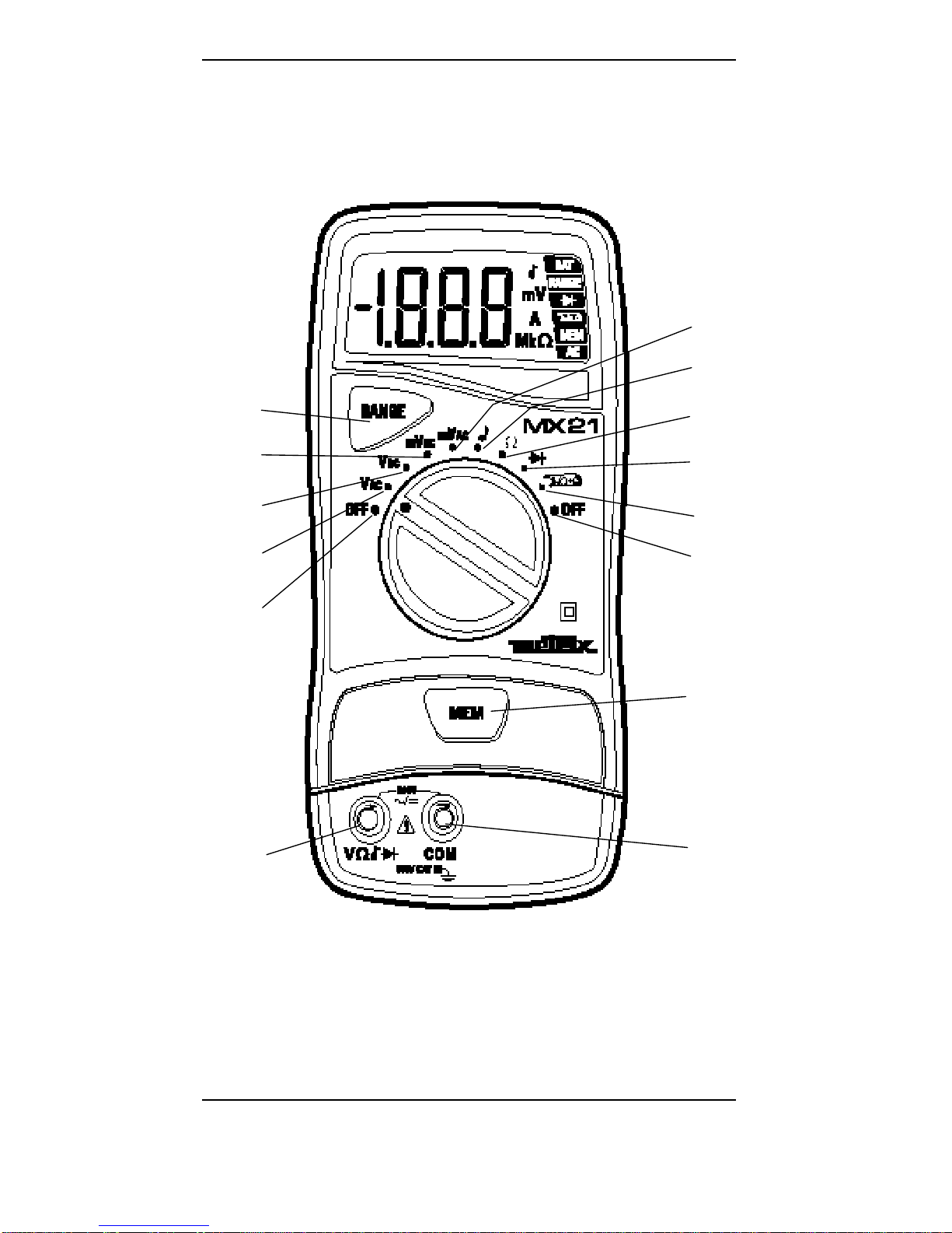
LEGENDE
1 Borne d’entrée 8Mesure de tension : 20 mVDC
2 Entrée de référence du multimètre 9Mesure de tension : 200 mVAC
3 Changement de gamme “ RANGE ” 10 Test de continuité :
4 Maintien de l’affichage “ MEM ” 11 Mesure de résistance : Ω
5 Mise hors tension “ OFF ” 12 Testeur de diode :
6 Mesure de tension VAC 13 IAC (avec pince, en option)
7 Mesure de tension VDC 14 Mise hors tension “ OFF ”
LEGEND
1 Input terminal 8Voltage measurement: 20 mVDC
2 Multimeter reference input 9Voltage measurement: 200 mVAC
3 Range change “ RANGE ” 10 Continuity test :
4 Display hold “ MEM ” 11 Resistance measurement : Ω
5 Power off “ OFF ” 12 Diode test :
6 AC voltage measurement 13 IAC (with clamp, optional)
7 DC voltage measurement 14 Power off “ OFF ”
BESCHREIBUNG
1 Eingangsbuchse 8Messung von Spannung: 20 mVDC
2 COM-Eingangsbuchse 9Messung von Spannung: 200 mVAC
3 Bereichsumschaltung “ RANGE ” 10 Durchgangsprüfung :
4 Anzeige-Speicherung “ MEM ” 11 Widerstandsmessung : Ω
5 Multimeter ausschalten “ OFF ” 12 Diodentest :
6 Messung von AC-Spannung 13 IAC (mit Zange, Option)
7 Messung von DC-Spannung 14 Multimeter ausschalten “ OFF ”
LEGENDA
1 Morsetto ingresso 8Misura di tensione : 20 mVDC
2 Ingresso di riferimento del multimetro 9Misura di tensione : 200 mVAC
3 Cambiamento di portata “ RANGE ” 10 Test de continuità :
4 Blocco lettura su display “ MEM ” 11 Misura de resistenza : Ω
5 Spegnimento “ OFF ” 12 Test diodo :
6 Misura di tensione AC 13 IAC (tramite pinza, opzional)
7 Misura di tensione DC 14 Spegnimento “ OFF ”
LEYENDA
1 Borne de entrada 8Medida de tension : 20 mVDC
2 Entrada de referencia del multímetro 9Medida de tension : 200 mVAC
3 Cambio de calibre “ RANGE ” 10 Test de continuidad :
4 Memorización de la pantalla “ MEM ” 11 Medida de resistencia : Ω
5 Puesta fuera de servicio “ OFF ” 12 Test diodo :
6 Medida de tension AC 13 IAC (con pinza, opcional)
7 Medida de tension DC 14 Puesta fuera de servicio “ OFF ”

Portable 2000 count digital multimeter 13
USER’S MANUAL
CONTENTS
1. GENERAL INSTRUCTIONS.........................................................14
1.1 Precautions and safety measures...............................................14
1.1.1 Preliminary.........................................................................14
1.1.2 During use..........................................................................15
1.1.3 Symbols .............................................................................15
1.1.4 Instructions.........................................................................15
1.2 Protection mechanisms...............................................................16
1.3 Safety mechanisms.....................................................................16
1.4 Warranty......................................................................................16
1.5 Maintenance and metrological verification ..................................17
1.6 Unpacking - Repackaging ...........................................................17
1.7 Cleaning ......................................................................................17
1.8 Replacing the battery...................................................................17
2. DESCRIPTION..............................................................................18
2.1 Display.........................................................................................18
2.2 Keypad ........................................................................................18
2.3 Selector switch ............................................................................18
2.4 Terminals (∅4 mm) ....................................................................18
3. FUNCTION DESCRIPTION ..........................................................19
3.1 AC or DC voltages.......................................................................19
3.1.1 mVDC and mVAC positions..................................................19
3.1.2 VDC and VAC positions........................................................19
3.2 Resistance...................................................................................19
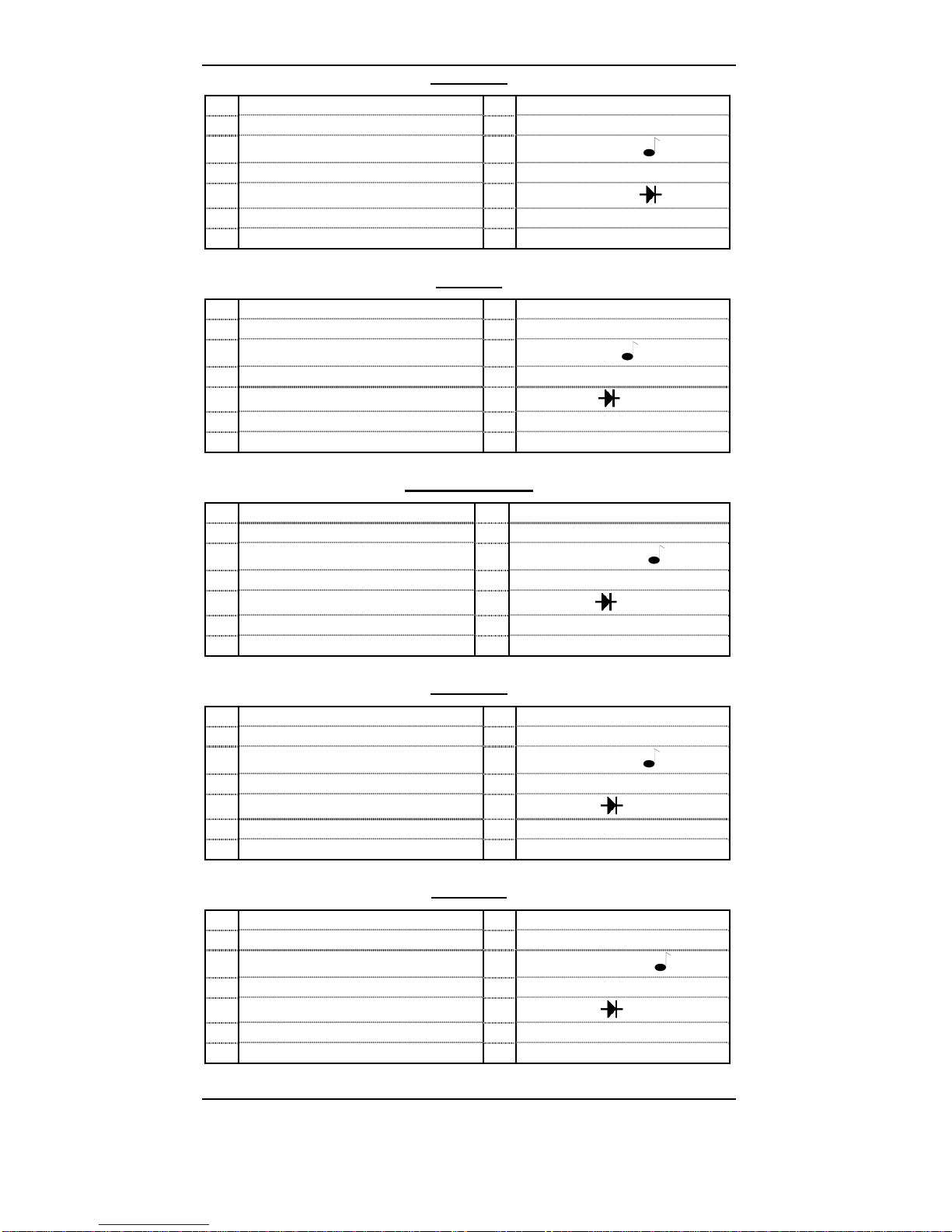
3.3 Continuity sound test ..............................................................20
3.4 Diode test .............................................................................20
3.5 Battery test ..................................................................................20
3.6 Current measurement (with clamp, optional)...............................20
4. GENERAL SPECIFICATIONS...................................................... 21
5. ACCESSORIES.............................................................................21
5.1 Delivered with the multimeter......................................................21
5.2 Optional.......................................................................................21

Portable 2000 count digital multimeter
14
1. GENERAL INSTRUCTIONS
You are the new owner of a 2000 count portable digital multimeter and
we thank you for your choice.
This instrument complies with the specifications set out in the NF EN
61010-1, publication concerning safety requirements for electronic
measuring apparatus.
To get the best service from this instrument, read carefully this user's
manual and respect the detailed safety precautions.
The contents of this manual must not be reproduced in any form
whatsoever without our consent.
1.1 Precautions and safety measures
1.1.1 Preliminary
∗This device can be used for measurements on category ΙΙΙ
installations, for voltages never exceeding 600 V (AC or DC)
relative to the earth.
∗Definition of overvoltage categories (see IEC 664-1 publication) :
CAT I: The CAT I circuits are protected by measures limiting
transient overvoltages to appropriate low level.
Example : protected electronic circuits
CAT II : The CAT II circuits are power supply circuits of
appliances or portable equipment with transient
overvoltages of an average level.
Example : appliances and portable equipment
CAT III : The CAT III circuits are power supply circuits of power
equipment with high transient overvoltages.
Example : fixed installation or industrial equipment
CAT IV :The CAT IV circuits may comprise very important
transient overvoltages.
Example : primary supply level
∗When using this multimeter, the user must observe all normal
safety rules concerning:
- protection against the dangers of electric current.
- protection of the multimeter against misuse.
∗For your own safety, only use the test probes supplied with the
instrument. Before use, check that they are in good condition.

Portable 2000 count digital multimeter 15
1.1.2 During use
∗Never exceed the protection limit values indicated in the specifications
for each type of measurement.
∗When the multimeter is linked to measurement circuits, do not
touch unused terminals.
∗When the range of the value to be measured is unknown, check that
the range initially set on the multimeter is the highest possible or,
wherever possible, choose the autoranging mode.
∗Before changing functions, disconnect the test leads from the circuit
under test.
∗In TV repair work, or when carrying out measurements on power
switching circuits, remember that high amplitude voltage pulses at the
test points can damage the multimeter.
Use of a TV filter will attenuate any such pulses.
∗Never perform resistance or continuty measurements on live circuits.
1.1.3 Symbols
Warning: Risk of danger.
Refer to the operating manual to find out the nature of the potential
hazards and the action necessary to avoid such hazards.
Attention : Risk of electrical shock
Earth terminal
Equipment protected throughout by double insulation.
The rubbish bin with a line through it means that in the European
Union, the product must undergo selective disposal for the
recycling of electric and electronic material, in compliance with
Directive WEEE 2002/96/EC.
Conforms CE
Power supply : 9 V (6LF22) battery
1.1.4 Instructions
∗Before opening up the instrument, always disconnect from all sources
of electric current and make sure you are not charged with static
electricity, which may destroy internal components.
∗Any adjustment, maintenance or repair work carried out on the
multimeter while it is live should be carried out only by appropriately
qualified personnel, after having taken into account the instructions in
this present manual.
∗A "qualified person" is someone who is familiar with the installation,
construction and operation of the equipment and the hazards
involved. He is trained and authorized to energize and de-energize
circuits and equipment in accordance with established practices.
∗When the instrument is opened up, remember that some internal
capacitors can retain a dangerous potential even after the instrument
is switched off.

Portable 2000 count digital multimeter
16
∗If any faults or abnormalities are observed, take the instrument out
of service and ensure that it cannot be used until it has been
checked out.
∗It is recommended to remove the battery from the instrument if not
used.
1.2 Protection
mechanisms
This instrument is fitted with various protection mechanisms :
∗Varistor protection for limiting transients of over 600 V at the VΩ
terminal, particularly 6 kV pulse streams as defined by the French
standard IEEE 587.
∗A PTC (positive temperature coefficient) resistor protects against
permanent overvoltages of up to 600
V during resistance,
continuity and diode test measurements. This protection is reset
automatically after overload.
∗An IP protection rating of 40.
1.3 Safety mechanisms
∗The battery unit cannot be accessed without first disconnecting
the measuring leads.
∗If the maximum range is repeatedly exceeded, an intermittent
audible signal warns the user in VAC, VDC, mVDC, mVAC, IDC,
functions.
1.4 Warranty
This equipment is warranted against any defects of manufacture or
materials according to the general conditions of sale.
During the warranty period (1 year), defective parts will be replaced,
the manufacturer reserving the right to repair or replace the product. In
the event of the equipment being returned to the after sale department
or to a local agency, carriage to the centre shall be payable by the
customer. The warranty does not cover the following :
1. Repairs necessitated by misuse of the equipment or use in
association with incompatible equipment.
2. Modification of the equipment or any related software without the
explicit authorization of the manufacturer.
3. Repairs necessitated by attempts to repair or maintain the product
made by a person not approved by the manufacturer.
4. Adaptation to a specific application not provided for in the
specifications of the equipment or the user manual.
5. Damage after a drop, a shock or flooding.
Portable 2000 count digital multimeter 17
1.5 Maintenance and metrological verification
Return your instrument to your distributor for any work to be done
within or outside the guarantee.
1.6 Unpacking - Repackaging
This equipment has been fully checked out mechanically and
electrically before shipping.
All precautions have been taken to ensure that the instrument arrives
at its destination undamaged.
However, it is advisable to carry out a rapid check for damage
sustained in shipping. If there is any evidence of damage, make this
known immediately to the shipper.
*Should you need to return the multimeter, preferably use
the original packaging and indicate the reasons as clearly
as possible on an accompanying note.
1.7 Cleaning
Clean the instrument using a damp cloth and soap. Never use
abrasive or solvents.
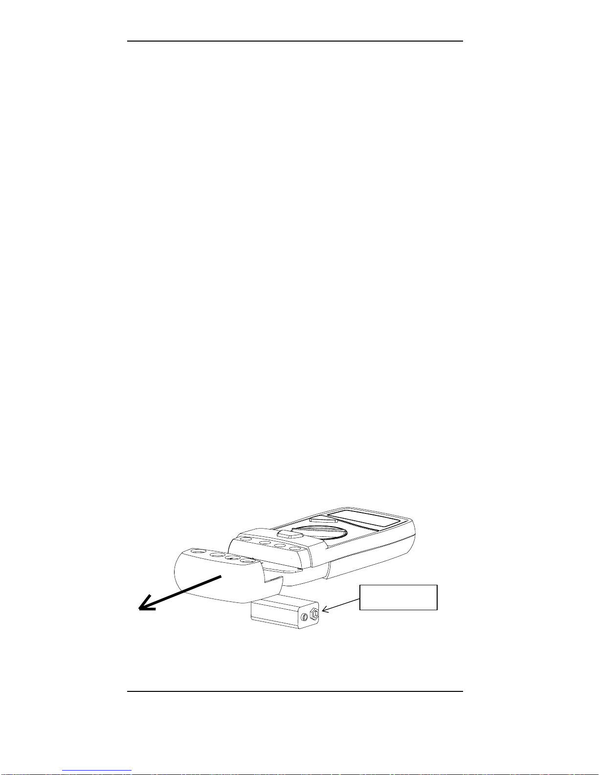
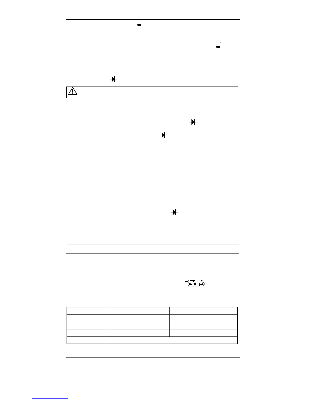
1.8 Replacing the battery
)Before replacing the battery, disconnect test leads from any
circuit under test, turn the meter off and remove test leads
from the input terminals .
Use the following procedure :
1 - Disconnect test leads from any inputs terminals.
2 - Using an appropriate tool, slide off the case bottom of the
instrument.
3 - Replace the battery.
4 - Replace the removable part.
BATTERY 9 V
6LF22

Portable 2000 count digital multimeter
18
2. DESCRIPTION
This compact multimeter is a self-contained unit with an appropriate
mechanical construction, enables hand-held use.
It is designed for a high degree of safety use and comes with a
maximum protection and unrivalled performance.
2.1 Display
•Liquid crystal display 3 ½ digits (height of digits : 18 mm)
•Function indicator : V, A, AC (default, otherwise DC), , Ω, ,
measurement with clamp (optional)
•« BAT» : battery discharge indicator
•« 1», on the left hand side, blinks and a beep sounds except
in Ωfunction : overrange.
•« MEM» : fixes the display on the current value.
•« AC » : the voltage measured by the instrument is an average
value.
•« RANGE » : manual mode in VDC, VAC, Ωranges.
2.2
Keypad
« RANGE » key :
•Selection of the automatic (default) or manual mode: short press
< 1 sec. on the key, the beep sounds briefly.
•Switch from manual to autoranging mode : long press > 1 sec., no
audible signal.
•In manual mode, range selection : press successively > 1 sec. on
the
key.
•This key is operative in VAC, VDC, Ωranges.
•Battery test in function
« MEM » key :
•Fixes the display on the current value and memorises it (short
press).
•A second short press returns the multimeter to normal mode.
2.3 Selector
switch
A 10-position rotary selector switch gives access to :
•AC voltage
•DC voltage
•Continuity (with beep)
•Resistance
•Diode
•Measurement with clamp (optional), widening the field of
applications of the multimeter
•OFF : Off position (2 positions)
2.4 Terminals
(∅4 mm)
•V, Ω, , : terminal receiving the red lead
•COM : terminal receiving the black lead
Portable 2000 count digital multimeter 19
3. FUNCTION DESCRIPTION
3.1 AC or DC voltages
•Connect the leads to the multimeter (COM and V terminals) and
connect it in parallel to the circuit to be tested.
•Position the selector switch on the voltmeter function « V or mV ».
•Automatic range selection : read the measured value.
•Memorise it, if necessary, by pressing the « MEM » key.
•Overload : the beep sounds and « 1» blinks.
•Specification in AC : from 5 % of the range.
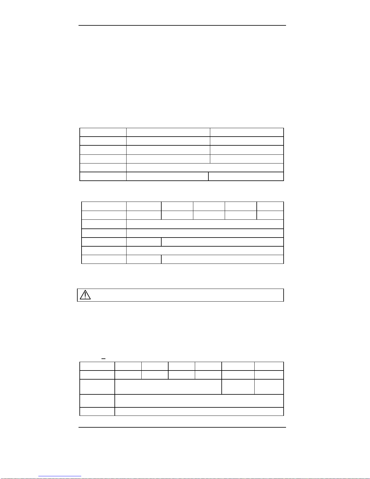
3.1.1 mVDC and mVAC positions
Range 20 mVDC 200 mVAC
Resolution 0.01 mV 0.1 mV
Impedance 5 MΩ3MΩ
Accuracy ± 1.5 % R ± 5 digits ± 2 % R ± 15 digits
Protection 600 Vrms
Bandwidth DC 40 Hz to 100 Hz
3.1.2 VDC and VAC positions
Range 200 mV (∗) 2 V 20 V 200 V 600 V
Resolution 0.1 mV 1 mV 10 mV 0.1 V 1 V
Impedance 5 MΩ
Accuracy DC ± 1 % R ± 4 digits
AccuracyAC - ± 1.5 % R ± 8 digits
Protection 600 Vrms
Bandwidth DC DC : 40 Hz to 500 Hz
(∗)in VDC only
3.2 Resistance
•Connect the leads to the multimeter (COM and Ωterminals) and to
the circuit or the component to be tested.
•Position the selector switch on the ohmmeter function « Ω».
•Automatic range selection : read the measured value.
•Memorise the value, if necessary, by pressing the « MEM » key.
•Overload : the beep sounds and « 1» blinks.
•IΩ: < 0.4 mA
Range 200 Ω2 kΩ20 kΩ200 kΩ2000 kΩ20 MΩ
Resolution 0.1 Ω1 Ω10 Ω100 Ω1 kΩ10 kΩ
Accuracy ± 1 % R ± 4 digits ± 1.5 % R
± 4 digits ± 3 % R
± 4 digits
Voltage on
open circuit < 2 V
Protection 600 Vrms
Never test a resistance on a live circuit.
Portable 2000 count digital multimeter
20
3.3 Continuity sound test
•Connect the leads to the multimeter (COM and Ωterminals) and to the
circuit or the component to be tested.
•Position the selector switch on the continuity sound function :
•The audible beep stops when R > 750 Ω.
•Protection : < 600 Vrms.
•Output voltage on open circuit : < 2 V
3.4 Diode test
With this function, it is not only possible to test classic diodes, but also
LED’s or any other semiconductor in which the junction corresponds to a
direct voltage less than 3 V.
•Connect the leads to the multimeter (COM and terminals) and to
the circuit or component to be tested.
•Position the selector switch on the « » function :
ªin forward bias, the display gives the value of the junction in V
(resolution 1 mV)
- accuracy : ± 2 % R ± 15 mV
- voltage on open circuit : 7 V typical
- short circuit current : 0.4 mA
ªin reverse bias, the display indicates the open circuit voltage (> 2 V).
•Memorise, if necessary, by pressing the « MEM » key.
•For measurements > 2 V, press the « RANGE » key.
•Protection : < 600 Vrms.
3.5 Battery test
•Position the selector switch on function « » diode.
•Remove the leads from the input terminals.
•Press the « RANGE » key. If the display indicates « < 4 V », only few
hours battery life remain until « BAT » (battery discharge indicator) is
displayed.
)The displayed value corresponds to the battery voltage -2 V.
3.6 Current measurement (with clamp, optional)
•Connect the leads of the clamp to the terminals of the multimeter
•[V (clamp) and COM].
•Position the selector switch on function clamp « ».
•Input impedance > 10 MΩ
•Overload : the beep sounds and « 1» blinks.
•Memorise, if necessary, by pressing the « MEM » key.
Multimeter Clamp
Range 0 to 200 A (*) 0.5 to 200 AAC
Resolution 0.1 A / 10 mV Ratio I/O : 100 mVDC / 1 AAC
Accuracy ± 1 % R ± 4 digits typical 2 %
Protection 600 Vrms
(*) Never perform any current measurement without clamp.
Never test a diode on a live circuit.

Portable 2000 count digital multimeter 21
4. GENERAL SPECIFICATIONS
•Mechanical
features :
Dimensions : 170 x 80 x 35 mm
Weight (with battery) : 285 g
•Packing : Dimensions : 230 x 155 x 65 mm
Weight : 385 g
•Power supply : 1 battery 9 V (type 6LF22 or 6LR61)
Battery life : approx. 300 hours with battery 6LR61
« BAT » : battery discharge indicator
•Buzzer : continuous beep for the continuity test
intermittent beep each time the switch is operated or
keys are pressed, and for overload indication
Response time < 500 ms
•Climatic
conditions :
Reference temprature : 23°C ± 5°C
Operating temperature : 0°C to 45°C
Use temperature : 0°C to 50°C
Storage Temperature : -20°C to 60°C
Relative humidity : use < 80 %
storage < 95 %
Protection rating : IP 40
•Safety : IEC 61010-1
Insulation : class 2
Pollution degree : 2
Indoor use
Altitude < 2000 m
CAT III, 600 V max. to earth
•EMC : Emission acc. EN 50081-1
Immunity acc. EN 50082-1
Influence in range 20 mVDC : + 2 mV
Influence in range Ohm : + 0.5 % (end of scale)
5. ACCESSORIES
5.1 Delivered with the multimeter
1 set of test leads..........................................................AG0475A
1 battery 9 V (6LF22).......................................................AL0042
1 protective elastomer case.......................................HX0002 (∗)
1 user’s manual..........................................................906129639
(
∗
) version « multimeter in a blister », only.
5.2 Optional
Mini-clamp..................................................................AM0089NZ
Protective elastomer case...............................................HX0002


METRIX
Parc des Glaisins
6, avenue du Pré de Challes
F - 74940 ANNECY-LE-VIEUX
Tél. 33 (0)4 50 64 22 22 - Fax 33 (0)4 50 64 22 00
906129639 - Ed. 6 - 01/13
Other manuals for MX 21
1
Table of contents
Other Metrix Multimeter manuals

Metrix
Metrix MX 21 User manual

Metrix
Metrix MX 59HD User manual

Metrix
Metrix MX 350 User manual

Metrix
Metrix Checkweigher User manual

Metrix
Metrix MX 1 User manual

Metrix
Metrix ASYC IV MTX 3292 Owner's manual

Metrix
Metrix MX 58HD User manual

Metrix
Metrix MTX 202 User manual

Metrix
Metrix MX 20 User manual

Metrix
Metrix MX 58HD User manual

Metrix
Metrix MX 57 EX User manual

Metrix
Metrix MX 24 User manual

Metrix
Metrix MX 26 User manual

Metrix
Metrix MX 1 User manual

Metrix
Metrix MX 26 User manual

Metrix
Metrix ASYC-IV MTX 3290 User manual

Metrix
Metrix MX 22 User manual

Metrix
Metrix MX 556 User manual

Metrix
Metrix MTX 3292 User manual

Metrix
Metrix MTX 3250 User manual


