Southworth APCU Series Operating instructions

Operating and Maintenance Manual
APCU Series
All Purpose Container Unloader
Model #: APCU
Serial # _________________________________________
Placed in Service _________________________________
December 2018
Southworth Products Corp
P.O. Box 1380 • Portland, ME 04104-1380
Telephone: 207-878-0700 Fax: 207-797-4734

2APCU Owner’s Manual
This label (part # 10095524)
is required by California law.
For more information visit
www.65Warnings.ca.gov.
This label (part # 10095524)
is required by California law.
For more information visit
www.P65Warnings.ca.gov.

APCU Owner’s Manual 3
CONTENTS
INTRODUCTION ................................................................................................. 4
RESPONSIBILITY OF OWNERS AND USERS ................................................... 5
SAFETY ALERT SYMBOLS AND SIGNAL WORDS............................................ 6
SAFETY .............................................................................................................. 7
Safety devices ......................................................................................... 8
INSTALLATION INSTRUCTIONS .................................................................... 20
Preparation .......................................................................................... 20
Positioning the lift .................................................................................. 20
Hydraulic connections ......................................................................... 20
Testing ................................................................................................... 21
Electrical connections............................................................................ 21
Checking the hydraulic system.............................................................. 21
OPERATOR CONTROLS ................................................................................. 22
OPERATING INSTRUCTIONS........................................................................... 22
OPTIONAL APCU SUPPORT STANDS ............................................................. 27
MAINTENANCE ................................................................................................. 28
Hazards ................................................................................................ 28
Servicing the unit safely ....................................................................... 28
Routine maintenance-weekly .............................................................. 28
Routine maintenance-monthly ............................................................. 29
Routine maintenance - 6 months or 500 hours ................................... 29
TROUBLESHOOTING ..................................................................................... 29
Troubleshooting Table ..................................................................... 30-31
ADJUSTMENT & REPLACEMENT PROCEDURES.......................................... 33
Aligning the photo eyes ......................................................................... 33
About the proximity switches ................................................................. 33
Setting end of travel for “tilt down” function ........................................... 33
Setting end of travel for “tilt up” function................................................ 33
Setting end of travel for “dump up” function .......................................... 33
Setting end of travel for “dump down” function...................................... 34
Inspecting and cleaning a control valve................................................. 34
Removing a cylinder .............................................................................. 34
Repacking a cylinder ............................................................................. 35
Replacing a cylinder .............................................................................. 36
ORDERING REPLACEMENT PARTS ............................................................... 45
WARRANTY ...................................................................................................... 46
List of Figures and Tables
Fig. 1 Overall View - Load Enclosure Lowered ................................ 8
Fig. 2A Operating Sequence - Loading Position .................................. 9
Fig. 2B Operating Sequence - Tilt 90 degree Position ......................... 9
Fig. 2C Operating Sequence - Dump Position.................................... 10
Fig. 3A-G Label diagrams and positions ......................................... 11-18
Fig. 3H APCU Support Stand Procedure............................................ 19
Fig. 4 Control panel.......................................................................... 22
Fig. 5A Using the retainer bar............................................................. 24
Fig. 5B Proper retaining...................................................................... 25
Table 1 Hydraulic Oil Specications.................................................... 32
Fig. 6 Repacking the cylinder ......................................................... 35
Fig. 7 Hydraulic schematic .............................................................. 37
Fig. 8 Wiring Diagram ................................................................ 38-39
Fig. 9 DC Power Supply Kit.............................................................. 40
Fig. 10 APCU Program Ladder Logic................................................. 41
Fig. 10A-C Hydraulic power unit ......................................................... 42-44

4APCU Owner’s Manual
Introduction
The Southworth All-Purpose Container Unloader (APCU) is designed to unload containers and pallets.
APCU units are designed for tilting and dumping of equipment and materials in a general indoor industrial
setting.
This manual contains instructions on the safe and proper installation, use, and maintenance of the All
Purpose Container Unloader unit. Be sure that this manual is available to the people who install, use, or
service the unit. Be sure that all personnel read this manual before they install, use, or service the unit.
The instructions in this manual are not necessarily all-inclusive, as Southworth cannot anticipate all
conceivable or unique situations. In the interest of safety, please read this whole manual carefully.
Please understand the material in this manual before you install, use, or service the APCU unit. If
you have any questions about any of the instructions in this manual, please contact Southworth
Products Corp.
Southworth’s product warranty is shown on the rear cover of this manual. This instruction manual is
not intended to be or to create any other warranty, express or implied, including any implied
warranty of merchantability or tness for a particular purpose, all of which are hereby expressly
excluded. As set forth more specically in the product warranty, Southworth’s obligation under that
warranty is limited to the repair or replacement of defective components, which shall be the buyer’s
sole remedy, and Southworth shall not be liable for any loss, injury, or damage to persons or property,
nor for any direct, indirect, or consequential damage of any kind resulting from the APCU unit.
This manual is intended for stand alone APCU machines
shipped about May 2015, and after with control panels supplied
Southworth Products. Please contact Southworth Products for
information about APCU machines shipped before May 2015 or
machines with control panels, control and hydraulic schematics,
PLC logic, or other differences that do not match those shown
in this manual.

APCU Owner’s Manual 5
Responsibility of Owners and Users
Inspection and Maintenance
The device shall be inspected and maintained in proper working order in accordance with South-
worth’s owner’s manual.
Removal from Service
Any device not in safe operating condition such as, but not limited to, excessive leakage, miss-
ing rollers, pins, or fasteners, any bent or cracked structural members, cut or frayed electric,
hydraulic, or pneumatic lines, damaged or malfunctioning controls or safety devices, etc. shall be
removed from service until it is repaired to the original manufacturer’s standards.
Deection
It is the responsibility of the user/purchaser to advise the manufacturer where deection may be
critical to the application.
Repairs
All repairs shall be made by qualied personnel in conformance with Southworth’s instructions.
Operators
Only trained personnel and authorized personnel shall be permitted to operate the lift.
Before Operation
Before using the device, the operator shall have:
• Read and/or had explained, and understood, the manufacturer’s operating instructions
and safety rules.
• Inspected the device for proper operation and condition. Any suspect item shall be care-
fully examined and a determination made by a qualied person as to whether it constitutes
a hazard. All items not in conformance with Southworth’s specication shall be corrected
before further use of the equipment.
During Operation
The device shall only be used in accordance with this owner’s manual.
• Do not overload.
• Ensure that all safety devices are operational and in place.
Modications or Alterations
Modications or alterations to any Southworth industrial positioning equipment shall be made
only with written permission from Southworth.

6APCU Owner’s Manual
SAFETY ALERT SYMBOLS AND SIGNAL WORDS
The safety of all persons operating, maintaining, repairing, or in the vicinity of this equipment is of paramount con-
cern. This is a powerful machine with moving parts, and is capable of causing personal injury if proper precautions are not
taken. Therefore, throughout this manual, certain hazards have been identied which may occur in the use of the machine,
and there are appropriate instructions or precautions which should be taken to avoid these hazards. In some cases, there
are consequences which may occur if instructions or precautions are not followed. Below are the symbols and signal words
along with their denitions referenced from ANSI Z535.4 - Product Safety Signs and Labels.
4.11 Safety Alert Symbols: A symbol that indicates a hazard. It is composed of an equilateral triangle surrounding
an exclamation mark. The safety alert symbol is only used on hazard alerting signs. It is not used on safety notice and safety
instructions signs.
4.14 Signal Words: The words used in the signal word panel. The signal words for hazard alerting signs are “DANGER,”
“WARNING,” and “CAUTION.” Safety notice signs use the signal word “NOTICE.” Safety instruction signs use signal words that
are specic to the situation.
DANGER indicates a hazardous situation which, if not avoided, will result
in death or serious injury.
WARNING indicates a hazardous situation which, if not avoided, could
result in death or serious injury.
CAUTION indicates a hazardous situation which, if not avoided, could
result in minor or moderate injury.
NOTICE is used to address practices not related to physical injury.
SAFETY INSTRUCTIONS (or equivalent) signs indicate specic safety-
related instructions or procedures.
NOTE: DANGER, WARNING or CAUTION should not be considered for property damage accidents unless personal injury risk
appropriate to these levels is involved.
A): for use with DANGER signal word; (safety white triangle, safety red exclamation mark, safety red background)
B): for use with WARNING signal word; (safety black triangle, safety orange exclamation mark)
C): for use with CAUTION signal word; (safety black triangle, safety yellow exclamation mark)
D) and E): for use with DANGER, WARNING, or CAUTION signal word; (D: is a safety yellow triangle with a
black border and safety black exclamation mark; E: is a safety yellow triangle with a safety black exclamation mark and a
safety yellow border around a safety black band)
NOTE: D and E are provided to allow for consistency with certain ISO standards such as ISO 3864-1 and ISO 3864-2.

APCU Owner’s Manual 7
Safety
Southworth is concerned about the safety of everyone who operates, maintains, repairs, or
works near the APCU unit. The unit is a powerful machine with moving parts, and is capable of
causing personal injury if proper precautions are not taken.
For this reason, throughout this manual, we have pointed out some of the hazards which may
occur as you use the unit. We have also listed the instructions or precautions you should take
to avoid these hazards. In some cases, we have also pointed out the consequences which may
occur if you do not follow these instructions or precautions. We will use the following system to
identify the severity of the hazards:
DANGER! – Immediate hazard which will result in severe personal injury or death.
WARNING! – Hazard or unsafe practice which could result in severe personal injury
or death.
CAUTION! – Hazard or unsafe practice which could result in minor personal injury or
property damage.
Please read and follow this instruction manual, including all safety instructions
and precautions, carefully and completely.
8APCU Owner’s Manual
Safety Devices
This unit has two kinds of safety devices. Guard fences
protect each side of the unit. These are designed to
keep everyone away from the moving parts of the unit
while it is operating. These guards should always be
in place when the unit is operating normally.
There may be some cases where you will want to do
maintenance work with the safety guards removed. You
should be especially careful during these procedures.
As the load enclosure moves up and down, “pinch
points” are created where the moving parts meet. If you
are standing too close to the load enclosure when it is
moving, your arm or leg may be caught in the moving
parts, and you may be hurt. Stay away from the pinch
points when the safety guards are removed and the load
enclosure is moving. Always replace the safety guards
as soon as you are done with the maintenance work.
The unit also includes three photo-eye systems.
Each photo-eye system includes a light source on one
side of the unit, and a reector on the other side. If
any of the light beams is broken, the unit will not start,
and the load enclosure will not move. This helps to
ensure that everyone is out of the way before the load
enclosure moves.
Before using the unit, please be sure that the guards
are in place, and that the photo-eye system is work-
ing. If the guards are missing, or the photo-eyes are
not working, turn off the machine right away and call
a supervisor. Never operate the unit without these
important safety features.
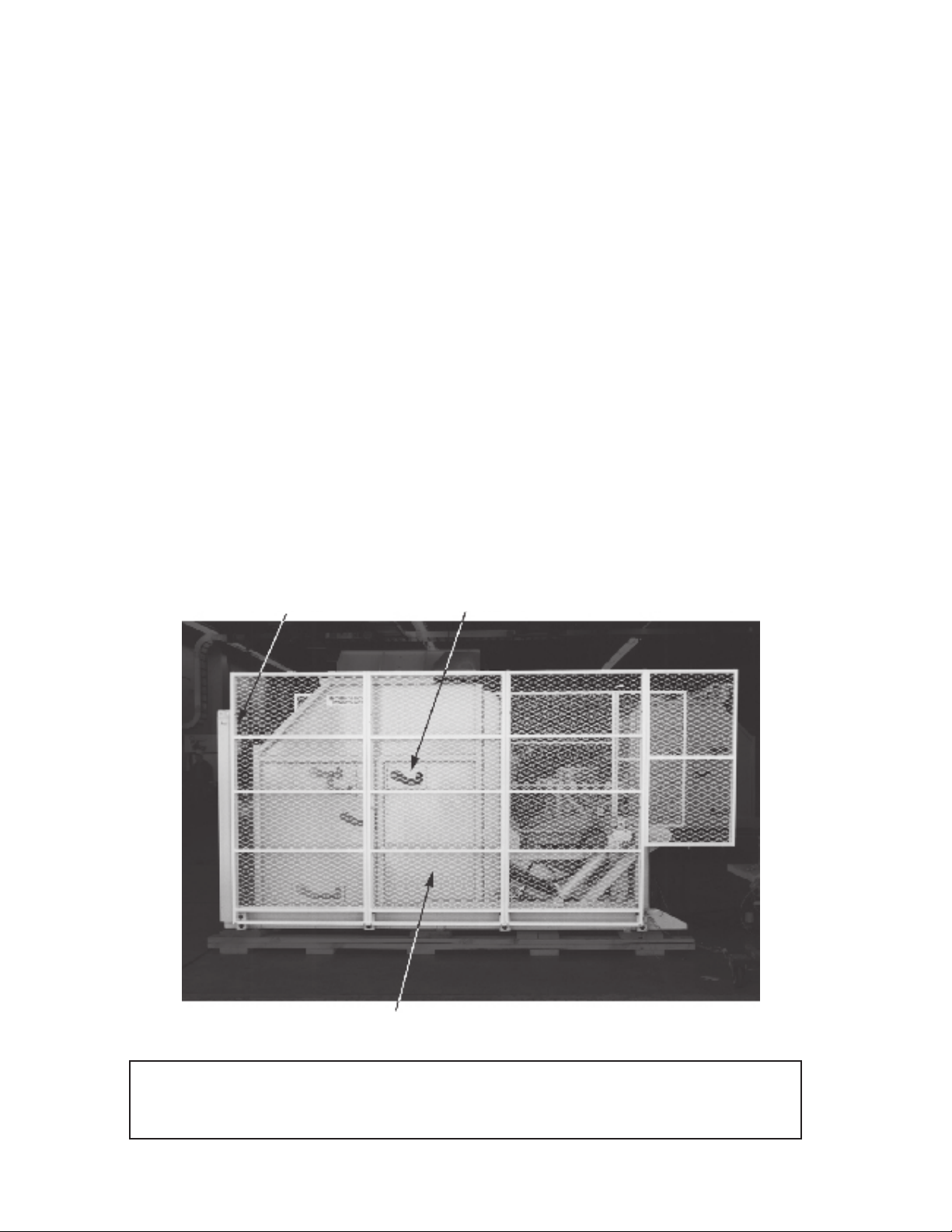
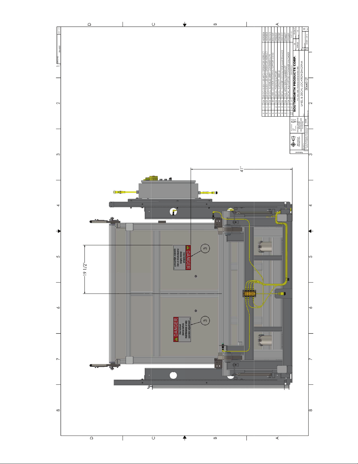
Figure 3 shows the positions of the warning labels
on the unit. These labels have been included for your
safety. If you nd that the labels are worn or missing,
or have been painted over, ask Maintenance to replace
the labels before you use the unit.
You should never operate the unit with the safety guards removed. This machine is equipped
with an external power unit, which is mounted a short distance away from the machine.
Fig. 1 Overall View
Safety photo-eyes Slots for retainer bar
Wire mesh enclosure

APCU Owner’s Manual 9
Fig. 2A Operating Sequence - Loading Position
Fig. 2B Operating Sequence - Tilt 90 degree Position

10 APCU Owner’s Manual
Fig. 2C Operating Sequence - Dump Position
Figure 2 shows the operating sequence for the unit.
At the start of the process, the operator places the pal-
let or container on the load enclosure. This enclosure
is positioned at ground level, so it is easy to load the
unit. (See Part A of the illustration.) During the “tilt”
part of the operating cycle, the load enclosure tilts up
90°. (See Part B.) Next, during the “dump” part of the
cycle, the enclosure can be tilted an additional 50° to
dump the items being loaded onto a conveyor or other
device. (See Part C.)
This manual contains information about the safe and
proper installation, use, and maintenance of an APCU
unit. Be sure that this manual is available to anyone
who works with the unit. Be sure that everyone who
uses the unit has read this manual.
The instructions included in this manual are not
necessarily all-inclusive, because Southworth cannot
anticipate all conceivable or unique situations.
In the interest of safety, please read this whole manual
carefully. Please understand the material in this manual
before you install, use, or service the APCU unit. If
you have questions about any of the instructions in this
manual, please contact Southworth Products Corp.
APCU Owner’s Manual 11
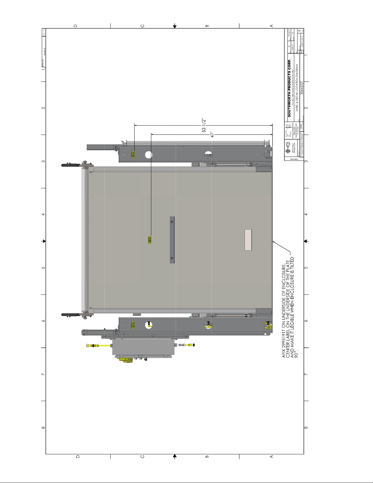
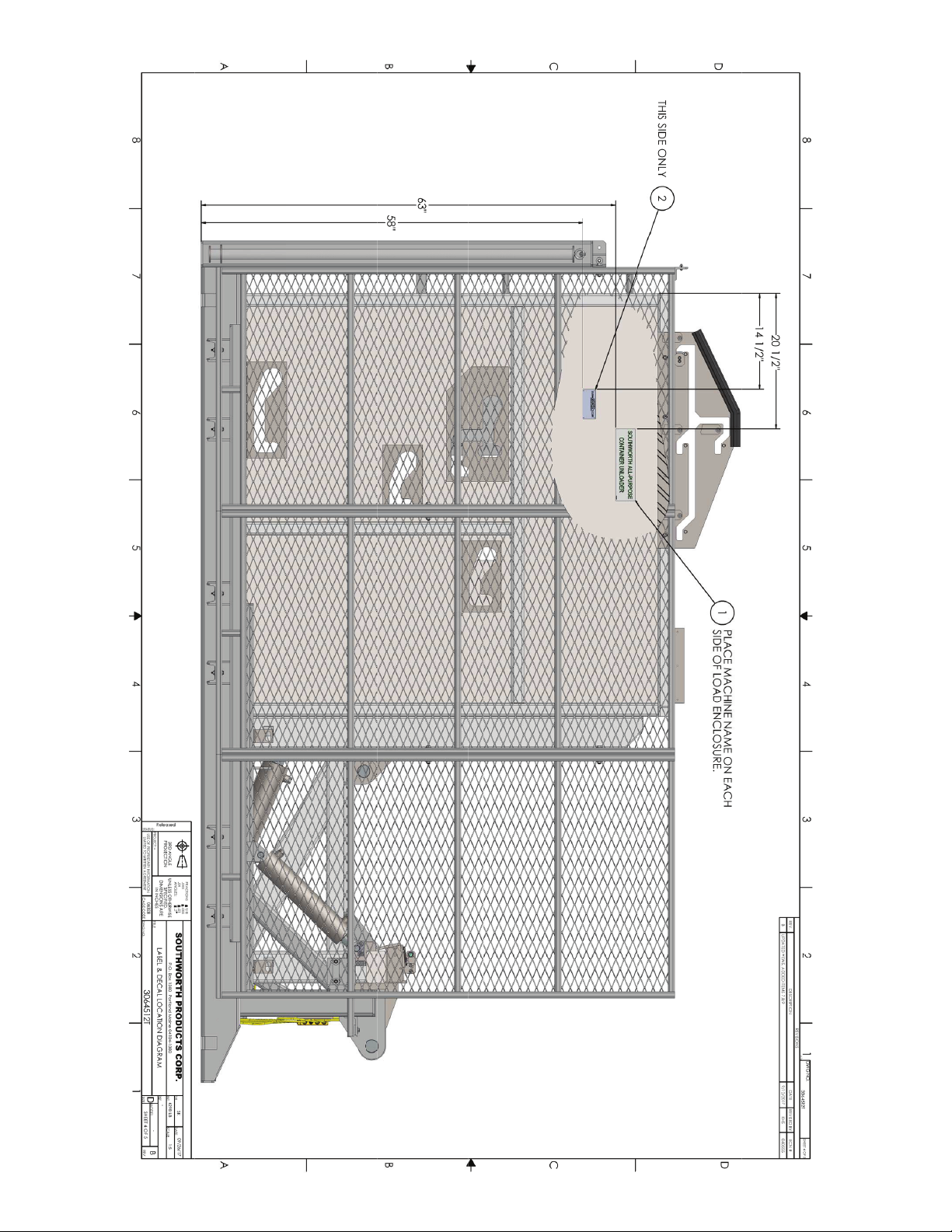
Fig. 3 - Label Diagrams and Positions

12 APCU Owner’s Manual
Fig. 3A - Label Diagrams and Positions
APCU Owner’s Manual 13
Fig. 3B - Label Diagrams and Positions
14 APCU Owner’s Manual
Fig. 3C - Label Diagrams and Positions
APCU Owner’s Manual 15
Fig. 3D - Label Diagrams and Positions
16 APCU Owner’s Manual
Fig. 3E - Label Diagrams and Positions
APCU Owner’s Manual 17
Fig. 3F - Label Diagrams and Positions
18 APCU Owner’s Manual
Fig. 3G - Label Diagrams and Positions
"NOTICE" label p/n-2998591T

APCU Owner’s Manual 19
TO RETURN APCU TO REGULAR SERVICE:
REMOVE LOCK OUT AND TURN ON THE MAIN POWER DISCONNECT ON THE APCU1.
POWER CONTROL PANEL.
USING THE CONTROL PUSHBUTTON RAISE THE TILT FRAME TO THE HIGHEST POSITION.2.
TURN OFF AND LOCK OUT THE SWITCH ON THE APCU POWER CONTROL PANEL.3.
REMOVE THE SUPPORT STANDS FROM THE LOAD AREA.4.
AFTER PERSONNEL ARE CLEAR FROM THE LOAD AREA REMOVE LOCK OUT AND5.
TURN ON THE MAIN POWER DISCONNECT ON THE APCU POWER CONTROL PANEL.
USING THE CONTROL PUSHBUTTON, LOWER THE LIFT FROM TO THE LOAD POSITION.
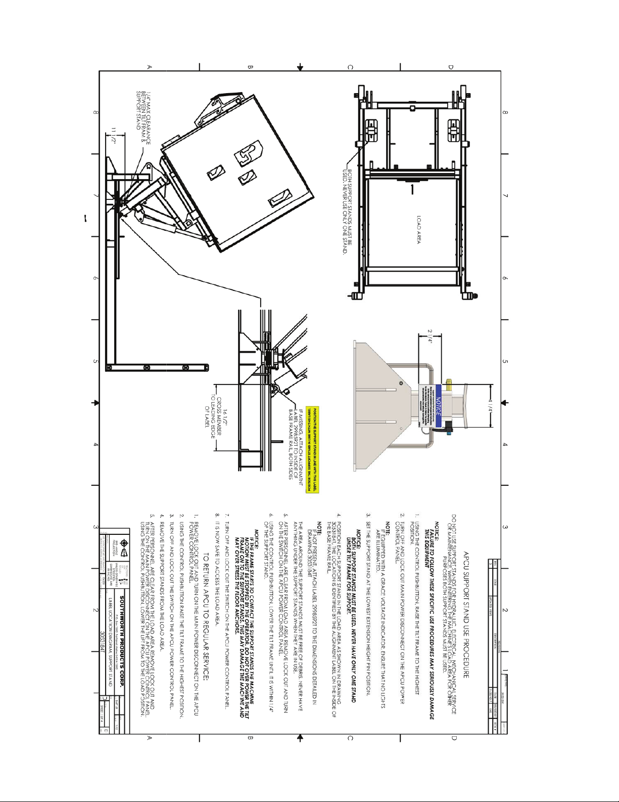
APCU SUPPORT STAND USE PROCEDURE
DO NOT USE SUPPORT STANDS FOR HYDRAULIC, ELECTRICAL, MECHANICAL SERVICE
OR MAINTENANCE. WHEN ENTERING THE MACHINE'S LOAD AREA FOR OTHER
PURPOSES BOTH SUPPORT STANDS MUST BE USED.
NOTICE:
FAILURE TO FOLLOW THESE SPECIFIC USE PROCEDURES MAY SERIOUSLY DAMAGE
THIS EQUIPMENT
USING THE CONTROL PUSHBUTTON, RAISE THE TILT FRAME TO THE HIGHEST1.
POSITION.
TURN OFF AND LOCK OUT MAIN POWER DISCONNECT ON THE APCU POWER2.
CONTROL PANEL.
NOTE:
IF EQUIPPED WITH A GRACE VOLTAGE INDICATOR, ENSURE THAT NO LIGHTS
ARE ILLUMINATED.
SET THE SUPPORT STAND AT THE LOWEST EXTENSION HEIGHT PIN POSITION.3.
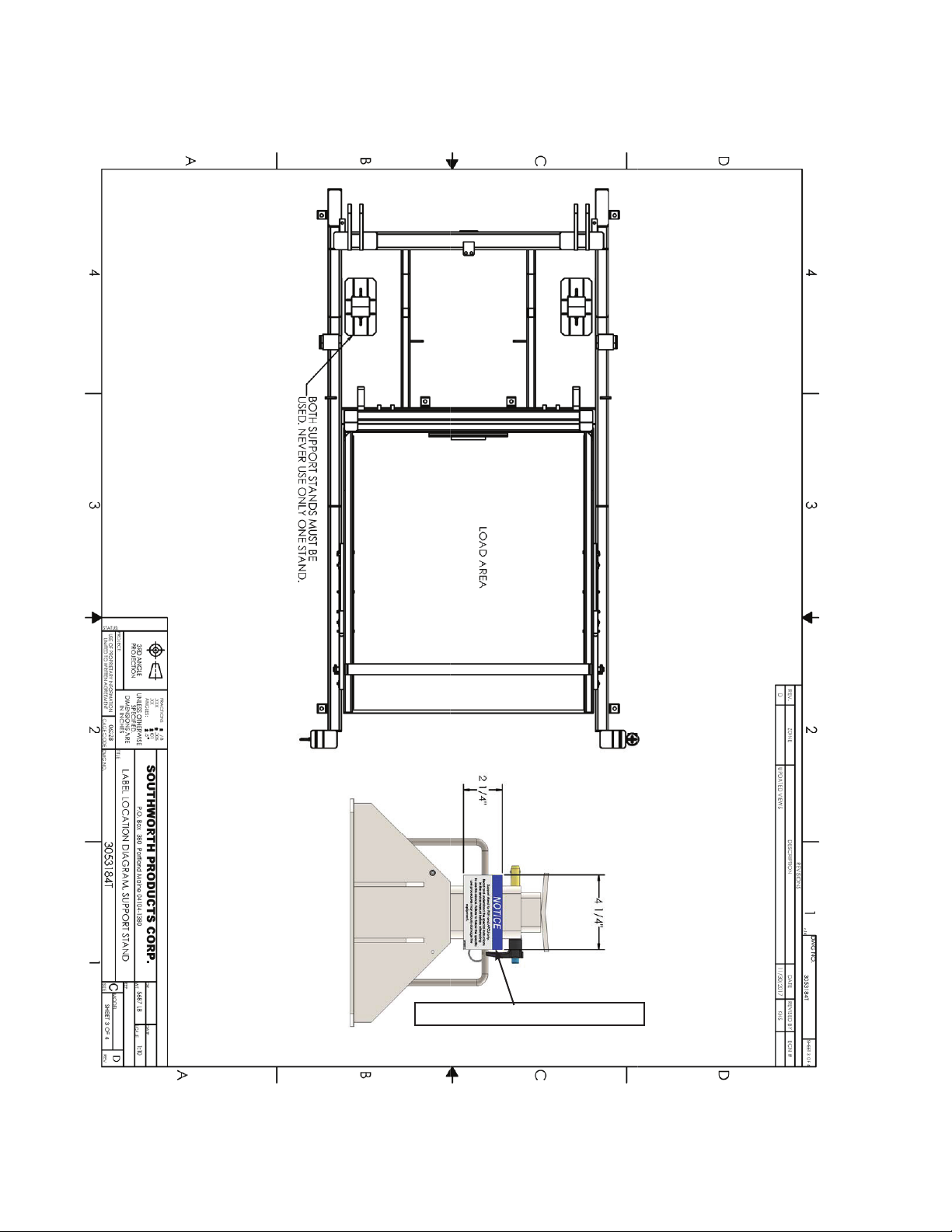
NOTICE:
BOTH SUPPORT STANDS MUST BE USED. NEVER HAVE ONLY ONE STAND
UNDER TILT FRAME FOR SUPPORT.
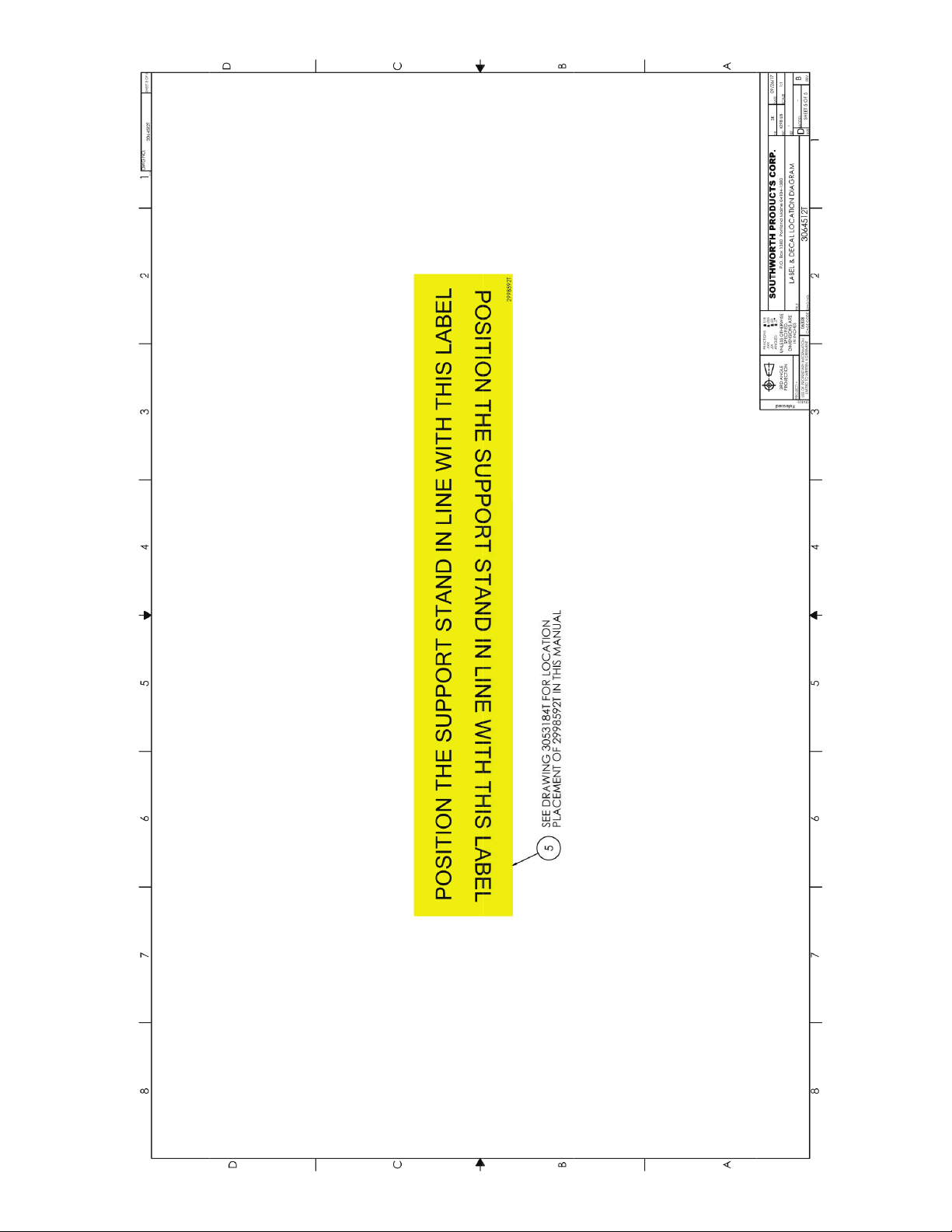
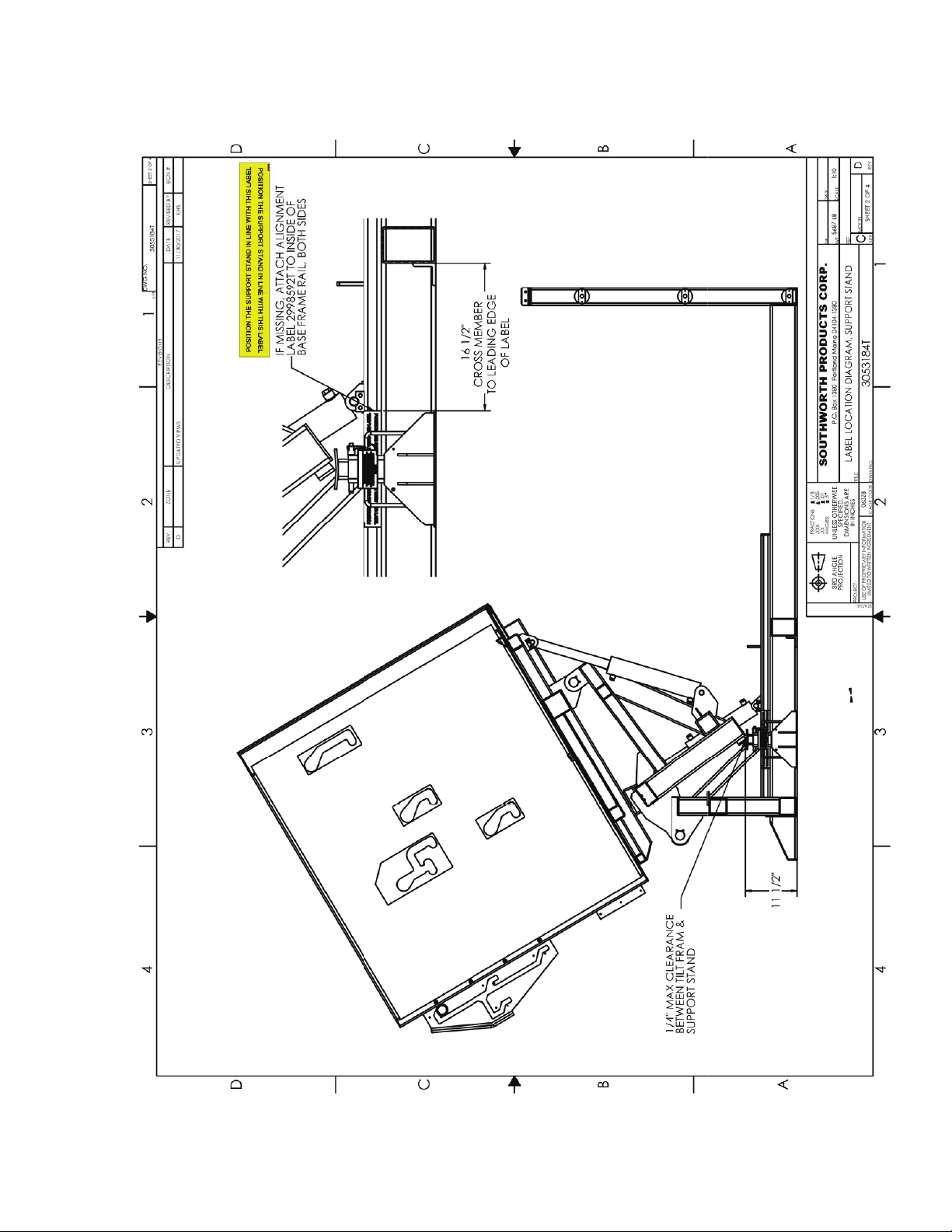
POSITION EACH SUPPORT STAND IN THE LOAD AREA AS SHOWN IN DRAWING4.
3053184T, THE LOCATION IS IDENTIFIED BY THE ALIGNMENT LABEL ON THE INSIDE OF
THE BASE FRAME RAIL.
NOTE:
IF NOT PRESENT, ATTACH LABEL 2998592T TO THE DIMENSIONS DETAILED IN
DRAWING 3053184T
THE AREA AROUND THE SUPPORT STANDS MUST BE FREE OF DEBRIS. NEVER HAVE
ANYTHING UNDER THE SUPPORT STANDS WHEN THEY ARE IN USE.
AFTER PERSONNEL ARE CLEAR FROM LOAD AREA REMOVE LOCK OUT AND TURN5.
ON THE SWITCH ON THE APCU POWER CONTROL PANEL.
USING THE CONTROL PUSHBUTTON, LOWER THE TILT FRAME UNTIL IT IS WITHIN 1/4"6.
OF THE SUPPORT STAND.
NOTICE:
IF THE FRAME STARTS TO CONTACT THE SUPPORT STANDS THE MACHINE
MOTION MUST BE STOPPED BY THE OPERATOR. DO NOT OVER POWER THE TILT
FRAME ON TO THE SUPPORT STANDS. THIS MAY DAMAGE THE MACHINE AND
MAY OVER STRESS THE FLOOR ANCHORS.
TURN OFF AND LOCK OUT THE SWITCH ON THE APCU POWER CONTROL PANEL.7.
IT IS NOW SAFE TO ACCESS THE LOAD AREA.8.
REVISIONS
REV. ZONE DESCRIPTION DATE REVISED BY ECN #
D UPDATED VIEWS 11/30/2017 KHS
DATE
MODEL
PROJECT: C
4 32
1
1234
A
B
C
D D
C
B
A
v.14
DWG NO.
3053184T SHEET 4 OF 4
1:1
D
SOUTHWORTH PRODUCTS CORP.
3053184T REV
TITLE
USE OF PROPRIETARY INFORMATION
DWG NO.
SCALE
UNLESS OTHERWISE
SPECIFIED.
DIMENSIONS ARE
PROJECTION
LABEL LOCATION DIAGRAM, SUPPORT STAND
5687 LB
IN INCHES
SIZE
P.O. Box 1380 Portland Maine 04104-1380
STATUS:
3RD ANGLE
LIMITED TO WRITTEN AGREEMENT
WT
CAGE CODE
063Z8 SHEET 4 OF 4
DR
REF
FRACTIONS 1/
.XXX .005
.XX .01
ANGLES: .5
8
Fig. 3H

20 APCU Owner’s Manual
Installation Instructions
Preparation
1. Before you start to use the unit, check for local
codes and ordinances which may apply. It is your re-
sponsibility to obtain any necessary permits.
2. Read all of these installation instructions carefully.
Be sure to read and understand all of the warnings.
3. Select the location where the unit will be installed.
Choose a location where the oor is rm, at and level.
As the unit operates, it is very important that the front
edge (the load edge) of the load enclosure touches the
oor at the same time as the rest of the bottom plate
touches.
CAUTION!
If the middle or back edge of the bottom
plate touches the oor before the front
edge of the load enclosure, the machine
may try to tip itself off the oor. This can
happen if the oor surface is not at.
WARNING!
• If the unit is mounted on an unstable
surface, it may tip over when in use. You
may be hurt, and the unit and load may be
damaged.
• Protect the unit from rain or moisture.
If the electrical parts in the power unit get
wet, workers may be hurt by electrical
shock. The electrical parts may fail if they
are wet.
• The electric motor on the remote power
unit can create sparks. Do not install the
power unit in an area where ammable
gases may be present.
4. You will need these tools to install the unit:
• A lift truck that can lift the unit safely.
• Shims and appropriate lag bolts.
• A masonry drill and bit to drill the holes for the
lag bolts.
• Extra hydraulic oil for ushing the hydraulic
lines and relling the tank.
• Level.
Positioning the Lift
1. Remove the shipping material and unskid the unit.
On the front of this manual, write down the model num-
ber, serial number, and date the unit is placed in service.
You can nd the model number and serial number on
the name plate.
2. Move the unit into position, supporting the base of
the unit. The base frame is tted with eyes for the lag
bolts. Drill the necessary holes and install the bolts.
CAUTION!
Do not hang the unit from the load enclo-
sure. This can damage the unit.
3. Check the movement of the load enclosure through
its full range.
CAUTION!
Take care not to create any “pinch points”.
Hydraulic Connections
1. Install the power unit. Run the hydraulic line be-
tween the power unit and the APCU but do not make
the connections yet. Be sure that the hydraulic line is
protected from passing trafc, and that it will not be
damaged.
WARNING!
Be sure that the hydraulic line will not be
pinched by the unit as it raises or lowers.
If you allow the line to be pinched, the unit
may not work properly. A hose may break,
the load enclosure may drop suddenly, and
someone may be hurt.
2. Before connecting the power unit, blow out the
hydraulic lines with compressed air.
CAUTION!
It is very important to keep the hydraulic
oil free of dirt, dust, metal chips, water, and
other contamination. Most of the problems
with hydraulic systems are caused by con-
tamination in the oil. Be sure all hydraulic
lines are free of contamination before con-
necting them to the remote power unit.
Table of contents
Other Southworth Industrial Equipment manuals


Popular Industrial Equipment manuals by other brands

Rockwell Automation
Rockwell Automation Allen-Bradley MicroLogix 1100 quick start

ABB
ABB HT846784 Operation manual

SWF
SWF SB Series installation manual

Eaton
Eaton NZM1-XDTV Series Instruction leaflet

Heinzmann
Heinzmann StG 40.90-09 PD instruction manual

Baldwin
Baldwin DAHL 300 Series Installation, Operation, Parts, Service Information


