Soyer SK-5AN User manual

Welding Head Operating Instructions
SK-5AN
SK-5AP
GB: English Version
Read these operating instructions before starting any work!
Doc.ID: P00251
Date of issue: 05.2013
www.soyer.de


___________________________________________________________________________________________________
3
Operating Instructions
SK-5AN
SK-5AP
Welding Head
Serial number*
SK-5AN Welding Head __________________________
Serial number*
SK-5AP Welding Head ___________________________
* Please enter the serial number here, so that the data is immediately
available if you need service support.
Heinz Soyer Bolzenschweißtechnik GmbH
Inninger Straße 14 | 82237 Wörthsee | Tel.: +49 8153 8850 | Fax: +49 8153 8030 | E-Mail: info@soyer.de | www.soyer.de

___________________________________________________________________________________________________
4
Thank you!
We congratulate you on purchasing your SOYER stud welding head. You have made an excellent choice. Your
SOYER stud welding head was especially developed for fastening SOYER welding studs as per DIN EN ISO
13918 on metallic workpieces at lightning speed.
Our devices have been tested and proven according to current European and national guidelines on health and
safety. Proof of conformity has been established and the manufacturer is in possession of the corresponding
documents.
SOYER®is a registered trade mark of Heinz Soyer Bolzenschweißtechnik GmbH.
It is prohibited to distribute or reprint this document. It is also prohibited to exploit or disclose its contents unless
permission has been expressly granted. Non-compliance with this regulation will lead to compensation for
damages. All rights reserved, particularly in the case of a patent grant or a GM registration.
We have verified that the contents of this pamphlet correspond to the hard- and software described. Deviations,
however, cannot be excluded so that we cannot warrant for absolute compliance.
The data in this documentation is verified regularly and any necessary corrections incorporated in future
impressions. Any suggestions for improvement are appreciated.
Date of issue: May 01, 2013
© Heinz Soyer Bolzenschweißtechnik GmbH 2013 · All rights reserved
Printed in the Federal Republic of Germany
FOR YOUR SAFETY
Read all of these operating instructions prior to start-up. Please
follow all safety precautions as well as all chapters of these
operating instructions before starting to weld. Non-compliance with
the safety precautions can result in serious personal injuries or
death.

___________________________________________________________________________________________________
5

___________________________________________________________________________________________________
6
Table of contents
1Safety instructions.........................................................................................................................................8
1.1 Description of reference signs in the operating instructions ...................................................................10
1.2 Staff qualification and training.................................................................................................................11
1.3 Dangers in the case of non-compliance with safety instructions ............................................................11
1.4 Before starting to weld... .........................................................................................................................11
1.5 Working with the stud welding equipment...............................................................................................11
1.6 Inadmissible operating methods .............................................................................................................11
1.7 Stopping the stud welding equipment.....................................................................................................11
2General ..........................................................................................................................................................12
2.1 The following should be principally observed... ......................................................................................12
2.2 Intended use............................................................................................................................................12
2.3 Marketing and service.............................................................................................................................12
2.4 Information on the documentation...........................................................................................................12
2.4.1 Information on operating instructions...............................................................................................13
2.4.2 Conduct in the case of malfunctions................................................................................................13
3Description of welding head .......................................................................................................................14
3.1 Welding process......................................................................................................................................14
3.1.1 Capacitor discharge.........................................................................................................................14
3.1.2 Drawn arc.........................................................................................................................................14
3.2 Different welding methods.......................................................................................................................15
3.2.1 Stud welding with shielding gas.......................................................................................................15
3.3 SK-5AN/SK-5AP welding head...............................................................................................................15
3.4 Dimensions..............................................................................................................................................16
3.5 Technical data.........................................................................................................................................17
4Adjustment of welding head .......................................................................................................................18
4.1 Adjustment of stud chuck........................................................................................................................19
4.2 Installation of stud chuck into welding head............................................................................................19
4.3 Adjusting the depth of immersion............................................................................................................20
4.3.1 Adjustment of immersion depth for SK-5AN welding head..............................................................21
4.3.2 Adjustment of immersion depth for SK-5AP welding head..............................................................23
4.4 Adjustment of the proximity switch..........................................................................................................24
4.5 Adjusting the height of lift........................................................................................................................25
4.6 Adjusting the speed of the lifting cylinder................................................................................................26
5Start-up..........................................................................................................................................................27
5.1 Installation of welding head into mounting device...................................................................................27
5.2 Connection of welding head to stud welder ............................................................................................27
5.3 Operation.................................................................................................................................................28
6Quality control (stud welding).....................................................................................................................29
6.1 General....................................................................................................................................................29
6.2 Demands on the company ......................................................................................................................29
6.3 Test execution.........................................................................................................................................30
6.3.1 Visual inspection..............................................................................................................................30
6.3.2 Bend test..........................................................................................................................................31
6.3.3 Production of samples .....................................................................................................................32
6.3.4 Tensile test.......................................................................................................................................32
7Maintenance..................................................................................................................................................33
8Troubleshooting ...........................................................................................................................................34
9Transport and storage .................................................................................................................................36

___________________________________________________________________________________________________
7
10 List of standards and guidelines.............................................................................................................37
11 Terms of warranty.....................................................................................................................................37

___________________________________________________________________________________________________
8
1 Safety instructions
These safety precautions are for your safety.
General safety instructions
Take part in a training programme. Read and follow all safety precautions listed below
and all chapters of this manual before starting to weld.
Non-compliance with the safety precautions can result in personal injuries or
death.
Only qualified persons are allowed to install, operate and maintain the equipment.
Children and juveniles under the age of 16 years must be kept away from the
equipment.
WARNING
It is prohibited to open the stud welding equipment.
The service personnel are required to meet special qualifications.
Our after-sales service has adequately trained personnel, suitable service equipment
and the means to carry out all necessary works.
Warning of electromagnetic fields
Keep sufficient distance from electronic devices. When stud welding, highly intensive
electromagnetic fields are created which may permanently damage these devices (e.g.
television sets, airbags).
Ensure that the welding equipment is not operated near electronically sensitive life-
support equipment, such as in intensive care units in hospitals.
Persons with pacemakers may neither operate the stud welding equipment nor stay in
the immediate vicinity while it is running.
Electric shock can cause death
Prevent electric shock by insulating your body from the working area and the ground.
Inspect all cables including power cord for damage, wear or bare wiring. Immediately
replace damaged or worn cables.
Always ensure the correct supply voltage in accordance with the data plate.
Never connect the welding equipment to a power supply network with incorrect supply
voltage.
Always disconnect the welding equipment from the mains supply before starting any
cleaning works. Only trained and appropriately qualified personnel are allowed to carry
out works at the electric mains supply and welding system.
Do not touch live electrical parts with bare hand. Wear dry, hole-free insulating gloves.
Do not wear rings, watches or electrically conductive jewellery.
Keep the work area, studs, guns, cables, energy source as well as your clothes dry.

___________________________________________________________________________________________________
9
Fumes and gases can cause damage to your health
Fumes and suspended/floating particles may be generated during welding. Beware of
fumes detrimental to health, particularly when using surface treated materials. Please
also observe the safety regulations applicable for your country.
Do not inhale fumes and gases. Use adequate ventilation in the work area to remove
fumes and gases.
Welding can cause fire and explosions
Welding sparks and heat from flames and arcs can cause fires. Keep a portable fire
extinguisher within reach for immediate use. Be sure you are trained to use it.
When welding, do not wear clothes soiled with easily combustible substances such as
oil, grease and paraffin oil etc.
Comply with the fire regulations and do not weld, for instance, in hazardous locations.
Pay attention to flammable objects at the welding place. All flammable materials and
liquids, such as oil, fuel, etc. must be removed prior to the start of work.
Electronic equipment (e.g. airbags) and the use of explosive substances for fuel supply
require further safety precautions when carrying out welding operations on cars.
Appropriate information can be obtained from the trade associations or the car
manufacturers.
Skin and eye protection
Arc rays and welding spatters can injure eyes and skin.
Wear safety glasses with side shields and protective goggles with correct shade of filter
to protect your eyes from welding spatters and flashes of light that are generated during
the welding process.
Wear gauntlet gloves made of leather as well as non-combustible closed working
clothes such as heavy long-sleeve shirts, cuffless pants and safety shoes.
Wear a leather apron to protect your clothes from welding spatters.
Keep sleeves and collars buttoned and remove open pockets from the front side of your
clothing.
We recommend using ear protection. Some welding and working processes may
generate loud noises.
___________________________________________________________________________________________________
10
1.1 Description of reference signs in the operating instructions
The non-observance of safety instructions such as pictographs and warning words can cause damage to
persons. The safety instructions of this operating manual describe the following:
Safety instructions
Danger!
Warning!
Immediate hazards which could result in serious personal injuries or loss of
life.
Potential hazards which could result in serious personal injuries or loss of
life.
Caution!
Caution!
Potential hazards which could result in minor personal injuries.
Warning of damage.
Note!
Important!
Potential detrimental situation which may cause damage to the product or
to an object surrounding it.
Instructions for application and other useful information facilitating the
proper use of the product.
Safety symbols
The following pictographs for warnings, prohibitions and regulations are used in this manual:
Prohibited for persons
with pacemakers
Prohibited (only in
combination with an
additional safety symbol)
Do not touch.
Housing is current-
carrying
Fire extinguisher
Warning of a danger
spot
Warning of dangerous
electric voltage
Warning of
electromagnetic field
Warning of moving
parts
General prohibition
(only in combination
with an additional
safety symbol)
Warning of inflammable
substances
Warning of explosive
substances
Eye protection required
Protective clothing
required
Ear protection
required
Protective gloves
required
General instructions are marked with the hand symbol.

___________________________________________________________________________________________________
11
1.2 Staff qualification and training
The staff responsible for operation, maintenance, inspection and assembly must have the respective
qualification for carrying out these works. Field of responsibility, competence and the supervision of staff must
be carefully regulated by the user. If your personnel do not have the necessary knowledge, they must be trained
and instructed. If necessary, this can be done by the manufacturer/supplier on behalf of the user. Furthermore,
the user must ensure that the contents of the operating instructions have been fully understood by the staff.
The society of welding institutes (GSI: Gesellschaft der Schweißtechnischen Institute mbH) offers the
appropriate training courses for your personnel.
For information on branches, please refer to website http://www.dvs-ev.de.
1.3 Dangers in the case of non-compliance with safety instructions
The non-compliance with safety instructions may not only endanger persons, but also the equipment and its
environment. Any non-compliance with safety instructions may result in a complete loss of damage claims.
The following dangers may result if the safety instructions are not complied with:
Failure of important system functions
Failure of prescribed methods for maintenance
Danger to persons through electrical, mechanical, thermal and/or acoustic influences
1.4 Before starting to weld...
Check the state of all cables and cable connections before starting to weld
Immediately replace defective cables and cable connections
1.5 Working with the stud welding equipment
Comply with all accident prevention regulations applicable to the operation of your welding device.
If an accident happens,
switch off the welding device and disconnect it from the mains supply and
call a doctor
1.6 Inadmissible operating methods
Limit values
The working safety of the supplied stud welding equipment is only guaranteed if the system is used in
accordance with its purpose. The limit values indicated in the chapter "Technical data" must never be exceeded.
1.7 Stopping the stud welding equipment
Turn off the mains switch of the stud welding equipment
Disconnect the mains plug from the mains socket
Disconnect the earth cable, control cable and welding cable from the stud welding equipment
Roll up the cables without buckling them
Prevent the stud welding equipment being operated by unauthorized personnel
Check welding cable and connections of the stud welding equipment for damage such as burn-off,
mechanical wear etc. and have damaged parts replaced by the SOYER customer service
___________________________________________________________________________________________________
12
2 General
2.1 The following should be principally observed...
With the SK-5AN/5AP welding head you have purchased a product which
is state-of-the-art technology
fully complies with the current safety requirements and
ensures high performance.
Before installing the welding head, please observe the following:
Store the operating instructions in a place accessible to every operator.
Ensure that the respective operator has read and understood the operating instructions prior to start-up.
Each operator should confirm this per signature.
Prevent the stud welding equipment being operated by unauthorized personnel.
Only trained personnel may operate the welding head.
DANGER
Persons with pacemakers must not operate the stud welding system and must not stay near it
while it is running. Ensure that the stud welding system is not operated near electronically
sensitive life-supporting equipment, such as in intensive care units in hospitals.
WARNING
Keep sufficient distance from electronic devices. When stud welding, highly intensive
electromagnetic fields are created which may permanently damage these devices (e.g. television
sets).
2.2 Intended use
The SK-5AN/SK-5AP SOYER®welding head allows you to weld pins and threaded studs from 3 –8 mm in
diameter and 6 –35 mm in length and many other types of cylindrical fastening elements manufactured of steel
and stainless steel.
If you need consultation or assistance in solving problems, please contact either our parent company or our field
engineers.
2.3 Marketing and service
If you have any questions regarding the operation of the welding equipment, retrofits for special applications or if
you require service, please contact your responsible service office or the following address:
Heinz Soyer Bolzenschweißtechnik GmbH
Inninger Straße 14
D-82237 Wörthsee
Telephone +49 (0) 8153 8850
Telefax +49 (0) 8153 8030
www.soyer.de
2.4 Information on the documentation
The following operating instructions are supplied with the SK-5AN/SK-5AP welding head:
• Operating instructions for SK-5AN /SK-5AP welding head Order no.: P00251

___________________________________________________________________________________________________
13
2.4.1 Information on operating instructions
Legal relationship
We point out that the contents of these operating instructions are neither part of any former or existing
arrangement, pledge or legal relationship nor have they been designed to modify the latter. All obligations of
Heinz Soyer Bolzenschweißtechnik GmbH result from the respective contract of purchase. This contract also
contains the complete and universally valid warranties. These contractual warranty terms are neither extended
nor restricted by the implementation of these operating instructions.
CAUTION
Do not carry out any actions on the stud welding equipment without specifically knowing the
operating instructions or the respective part. Ensure that only qualified and trained personnel
familiar with the operating instructions operate the system.
2.4.2 Conduct in the case of malfunctions
If malfunctions occur, first try to detect and eliminate the causes according to the list in chapter 8
"Troubleshooting" of these operating instructions. In all other cases, contact our service department.
If you require our service, please make sure that you supply us with the following information:
Customer number
Product designation / options
Serial number
Year of construction
Material of stud and workpiece
Stud dimensions
This information helps us save time and unnecessary costs, e.g. incurred by delivering the wrong spare parts.
___________________________________________________________________________________________________
14
3 Description of welding head
3.1 Welding process
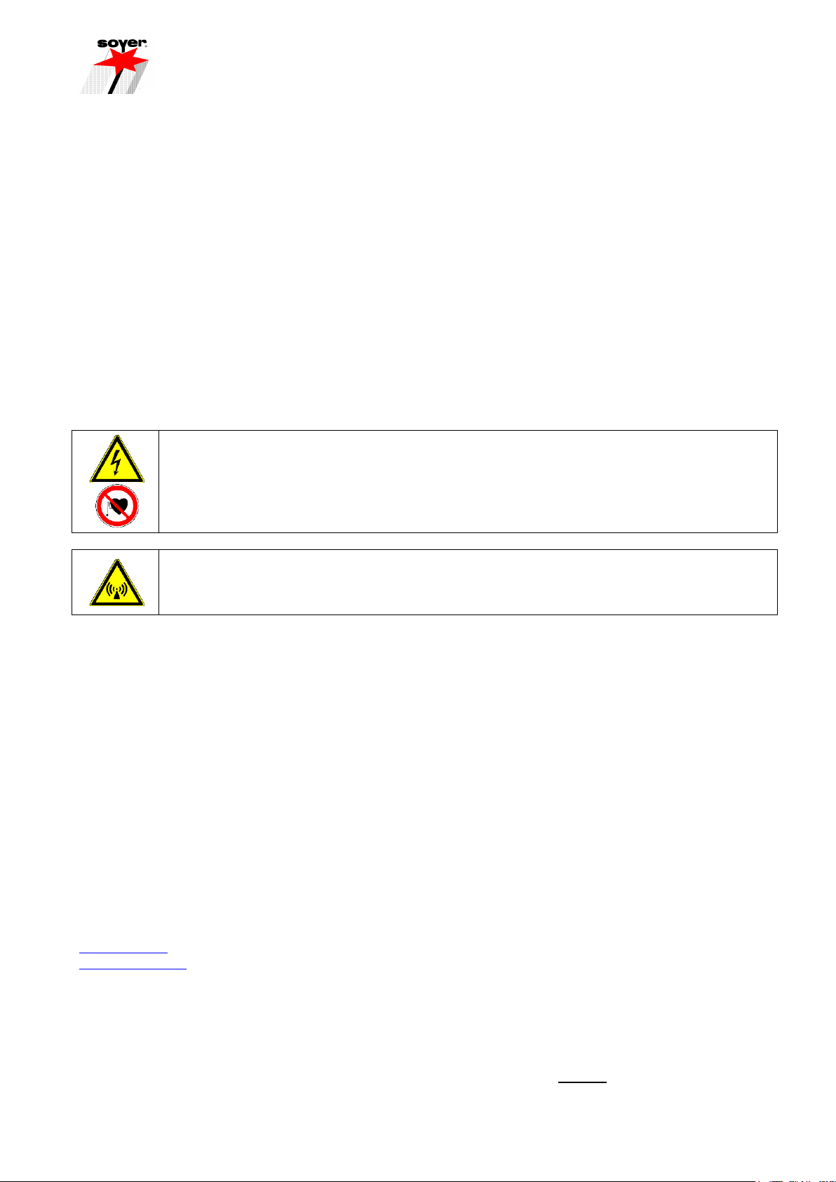
3.1.1 Capacitor discharge
Capacitor discharge welding allows threaded studs, pins, internally tapped bosses, insulating nails, flat plugs,
special studs and special welding elements from 2 –8 mm in diameter (in special cases up to Ø 10 mm) made
of steel and CrNi steel to be welded on metallic workpieces. Conditionally it is also possible to weld aluminium
and brass depending on the respective requirements. The inseparable weld joint is either carried out semi-
automatically or fully automatically. In the welding process, the welding energy stored in a capacitor bank is
discharged through the ignition tip of the welding stud within the extremely short time of 1 –3 ms (0.001 –0.003
sec.). Additional aids such as protective gas or ceramic ferrules are not required.
The stud tip is placed into contact
with the sheet.
Ignited electric arc generates a thin
fusion zone on stud and
workpiece.
The stud is immersed in the molten
pool. Material solidifies and stud is
welded.
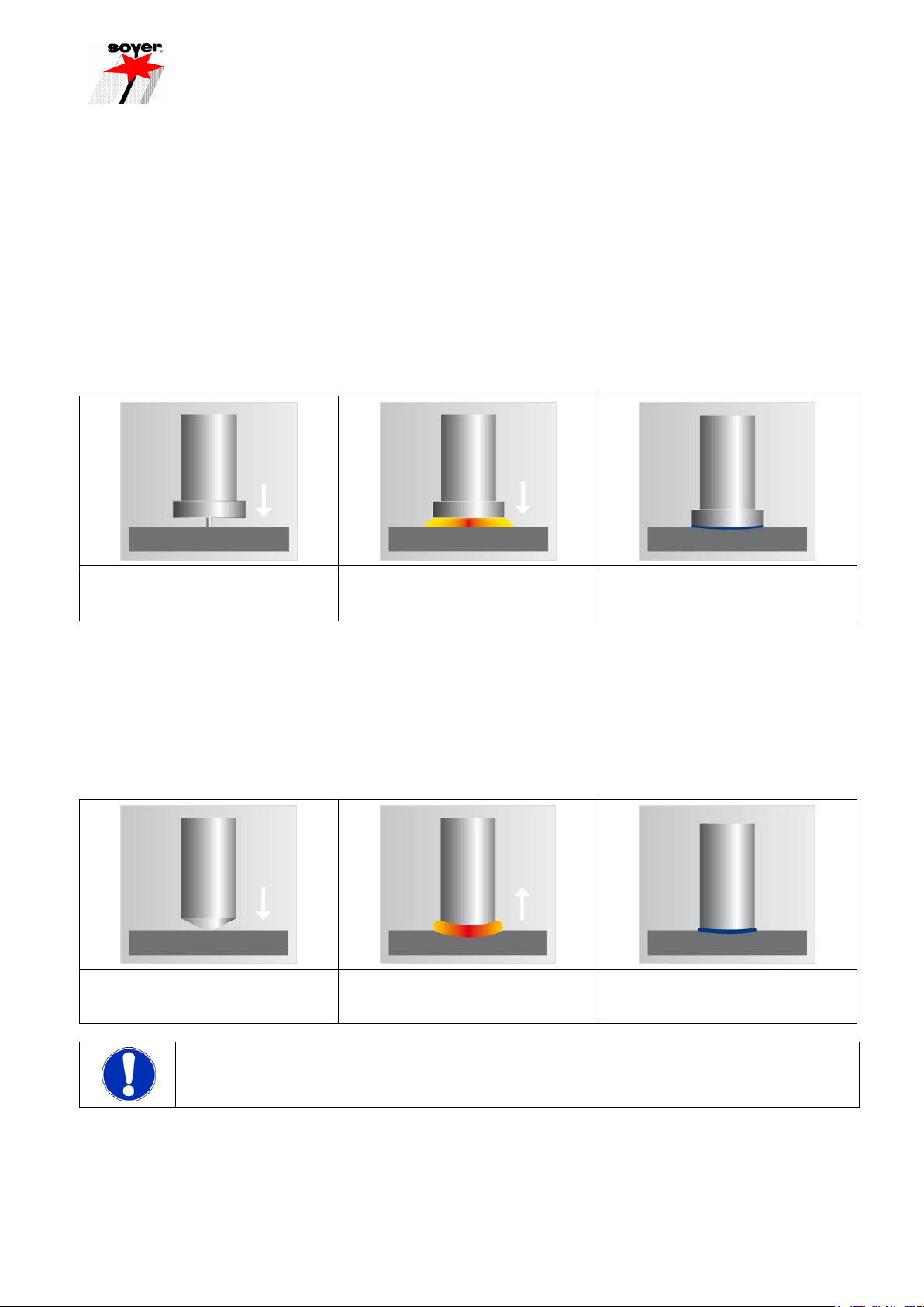
3.1.2 Drawn arc
Drawn arc stud welding serves to predominantly weld pin-shaped elements on metallic workpieces. This method
allows semi- and fully automatic inseparable welding of threaded studs, pins, shear connectors, flat pins,
internally tapped bosses, insulating pins and special studs from 3 –22 mm in diameter made of steel, CrNi
steel, heat-resistant steel, as well as in special cases aluminium, brass and titanium. A welding rectifier serves
as a source of energy which provides continuous welding power and can be regulated in weld time and power.
Weld time is 0.1 –2.0 sec. Shielding gas or ceramic ferrules are usually used as auxiliary aids.
The stud is placed on the plate.
The stud lifts to a preset height.
The arc is ignited.
The stud is immersed in the molten
pool. Material solidifies and stud is
welded.
IMPORTANT
Ensure that the surface is electroconductive, e.g. grind coated parts.

___________________________________________________________________________________________________
15
3.2 Different welding methods
The following welding methods are possible with the SK-5AN and SK-5AP SOYER welding heads:
Capacitor discharge stud welding
Drawn arc stud welding using shielding gas
Short-cycle drawn arc welding using shielding gas
3.2.1 Stud welding with shielding gas
With this method, Corgon18* is used as auxiliary aid. This shielding gas protects the welding point from the
atmosphere and simultaneously supports the weld pool. Moreover, it ensures a concave fillet weld bead
formation with a blank metallic surface; this reduces the risk of corrosion and leads to an improved dynamic
performance of the welded joint.
* Corgon 18 is a product designation of Linde AG. (Process gas as per DIN EN ISO 14175:M21 - ArC - 18)
Gas mixture containing 82% Argon (Ar) and 18% carbon dioxide (CO2)
3.3 SK-5AN/SK-5AP welding head
The SK-5AN and SK-5AP welding heads are suitable for being operated with capacitor discharge, drawn arc
and short-cycle drawn arc.
The compact and lightweight SOYER welding heads have a patented semi- and fully automatic stud feed
system (Pat. no. 0406 459). The welding heads can be easily and rapidly converted to other stud dimensions.
Possible jams caused by studs are immediately detectable and can be easily resolved due to free accessibility.
All connections are made with plug-in connectors to facilitate quick and easy start-up and maintenance.
The SK-5AN and SK-5AP welding heads are ideally suited for connecting to stationary machining centres, CNC
controlled machines, robots and handling systems etc.
For information regarding the stud welders to be used, please refer to the corresponding operating instructions
of the stud welders.

___________________________________________________________________________________________________
16
3.4 Dimensions
The SK-5AN and SK-5AP welding heads are designed in a handy and robust way and are easy to service. The
illustrations below show the welding heads.
SK-5AN welding head
Dimension "A"
Dimension "B"
Slide, 75 mm lift
185 mm
195.5 mm
Slide, 126 mm lift
225.5 mm
299 mm

___________________________________________________________________________________________________
17
SK-5AP welding head
Dimension "A"
Dimension "B"
Slide, 75 mm lift
185 mm
195.5 mm
Slide, 126 mm lift
225.5 mm
299 mm
3.5 Technical data
SK-5AN/SK-5AP welding head
Welding range - Studs
and pins
Ø 3 –8 mm and 6 –35 mm in length
Range of application
Steel, stainless steel - conditionally aluminium and brass,
depending on the respective requirements
Welding process
Capacitor discharge, drawn arc and short-cycle drawn arc
Welding sequence
up to max. 30 studs/min., depending on dimensions
Weight
4.5 kg with slide (lift 75 mm)
5.7 kg with slide (lift 126 mm)
Air connection
Operating pressure 6 bar minimum, 7 bar maximum
Power density for lifting movement and plunger movement
is 70 l/sec.
Subject to technical changes without prior notice

___________________________________________________________________________________________________
18
4 Adjustment of welding head
The welding head allows studs to be automatically fed through a stud feed tube directly into the stud chuck. The
plunger in combination with a selection of distance sleeves serves as a limit stop for welding studs of different
lengths.
The welding head with pneumatic slide is usually supplied in operative condition together with a mounting
device or a CNC bench welding machine.
Prior to start-up you should ensure, however, that a conversion kit is installed which is appropriate for the stud
to be welded. If need be, replace the conversion kit.
To do this, disconnect the air connections located at the front side of the stud welder. Make sure that the stud
welder is switched off!
In order to change the stud chuck, please remove the stud feed tube (item 2, chapter 4.2) from the welding head
and loosen the sleeve nut (item 3, chapter. 4.2) by means of a socket wrench SW 17.
The conversion kit allows the welding head to be set to different stud diameters and lengths. It consists of the
following components:
1. Stud feed tube
2. Stud chuck
3. Plunger
4. Distance sleeves

___________________________________________________________________________________________________
19
4.1 Adjustment of stud chuck
Choose the appropriate conversion kit for the respective stud diameter.
Insert weld stud into the opening of the stud chuck (ignition tip or stud flange must point in the direction
of the collet chucks of the stud chuck).
Insert plunger in the stud chuck and press stud flange through the collet chucks until a distance of
1.5 - 3 mm between the front edge of the stud chuck and stud flange is reached.
1. Stud
2. Plunger
3. Stud chuck
4. Distance sleeve
Insert a single distance sleeve or distance piece combination between plunger and stud chuck.
Stud (item 1) must make contact with the front end of the plunger (item 2).
Automatic stud feeding is possible up to a maximum stud length of 35 mm. Different stud diameters require
corresponding stud chucks, plungers, distance sleeves, feed tubes and stud feed hoses.
Range of application for automatic stud chucks (thread diameter x length) M3 x 6-35 mm, M4 x 8-35 mm, M5 x
8-35 mm, M6 x 10-35 mm, Ø 7.1 x 10⁻³⁵ mm, M8 x 10-35 mm.
4.2 Installation of stud chuck into welding head
1. Automatic stud chuck
2. Stud feed tube
3. Sleeve nut
4. Support retainer
5. Headless pin
Loosen sleeve nut (item 3, chapter 4.2) by means of socket wrench SW 17.
Insert stud chuck (item 1, chapter 4.2) with plunger into spring piston. Ensure correct fitting position
while doing so.
Tighten stud chuck (item 1, chapter 4.2) by means of sleeve nut (item 3, chapter 4.2). Hand-tighten
sleeve nut by means of socket wrench SW 17.

___________________________________________________________________________________________________
20
Push stud feed tube (item 2, chapter 4.2) through the support retainer (item 4, chapter 4.2). Ensure
correct positioning while doing so.
4.3 Adjusting the depth of immersion
MORTAL DANGER
The stud welder must be switched off before adjusting the depth of immersion.
Compressed air must be supplied and the stud must make contact with the front end of the
plunger.
The depth of immersion is the distance the stud immerses in the liquid molten pool on the workpiece during the
welding process. When positioning the welding head on the workpiece the weld stud is pushed back this
distance.
When correctly using a support tube, ceramic ferrule or a gas shroud, the stud must project correspondingly in
order to ensure a sufficient depth of immersion. The procedure for setting the depth of immersion is always the
same even when using a support tube, ceramic ferrule or a gas shroud. The depth of immersion always
depends on the respective stud diameter and welding task. An immersion depth of approximately 2 mm serves
as the standard value for all welding procedures.
Set the depth of immersion in such a way that the stud chuck cannot touch the workpiece when no stud is
inserted, otherwise the stud chuck will be welded with the workpiece.
This manual suits for next models
1
Table of contents


