SP tools SP61062 User manual
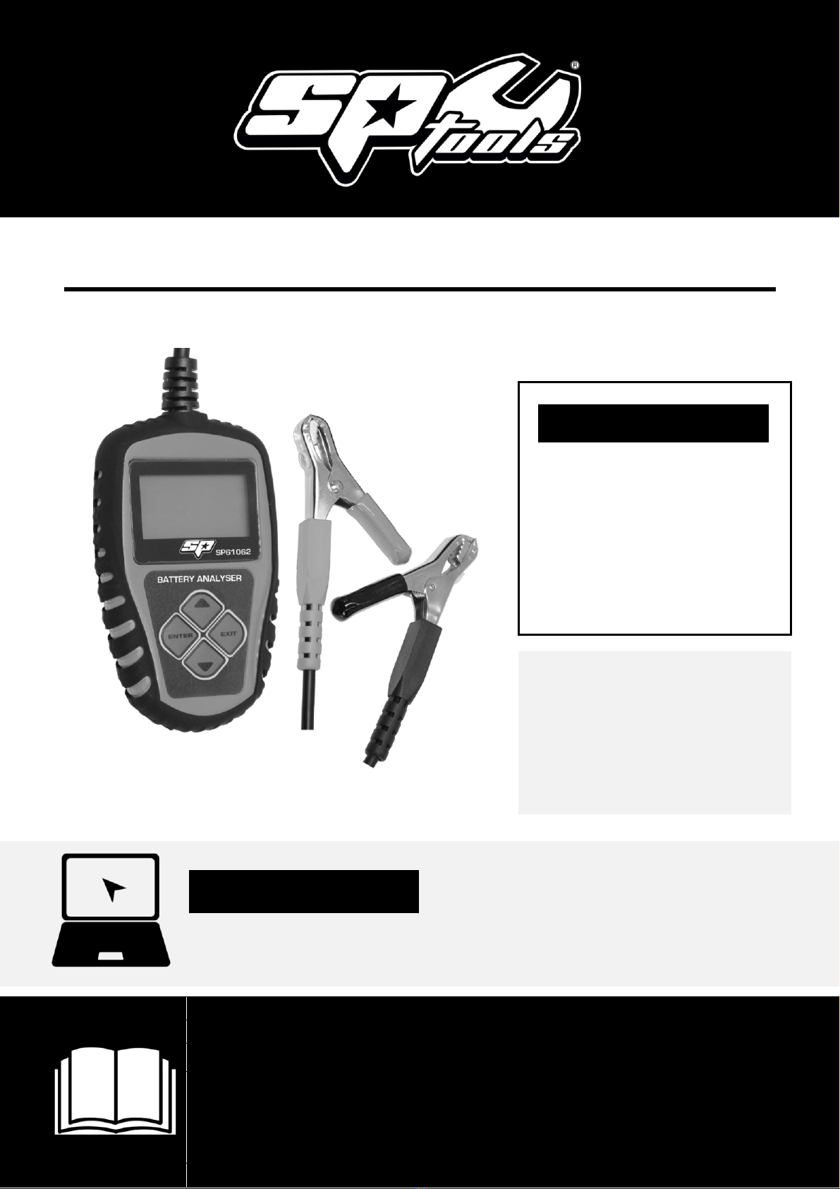
USER MANUAL
IMPORTANT
ALL PERSONS WHO ARE TO USE THIS EQUIPMENT MUST THOROUGHLY READ
AND UNDERSTAND THIS INSTRUCTION MANUAL PRIOR TO OPERATION.
SP61062
DELUXE BATTERY
ANALYSER /
CHARGING
SYSTEM TESTER /
CRANKING
SYSTEM TESTER
RETAIN THESE INSTRUCTIONS
AND ATTACH RECEIPT TO
MANUAL FOR FUTURE
REFERENCE
NOTE: Proof of purchase must be retained by
the customer as it will be required in the
event of a claim under warranty.
AFTER SALES SUPPORT:
AUSTRALIA: Visit the website’s contact page to get in
touch with your local service department.
WWW.SPTOOLS.COM
INTERNATIONAL: Use the county selector to get in touch
with your service department in your country or region.

2
CONTENTS
Product Profile 3
Product Function 3
Technical Parameters 4
Technical Specifications 4
Intended Use 4
Scope of Delivery 4
Security Precautions and Warnings 5
Tool Description 5
Internal Resistance Explanation 6
Voltage Explanation 6
Operating Instructions 6
Before Testing 6
Product Setup 7
Battery Test 8
Battery In-Vehicle Test 8
Battery System Standard and Rating 9
Rating Range 10
Battery In-Vehicle Test Result 10
Cranking Test 11
Charging System and Rectifier Diode Test 12
Battery Out-of-Vehicle Test 14
Battery Out-of-Vehicle Test Result 16
Review Data 17
Print Data 17
Cleaning and Maintenance 18
Disposal and Recycling Information 18
Warranty Information 19

3
PRODUCT PROFILE
The SP61062 Battery Tester adopts what is currently the world's most advanced conductance
testing technology to easily, quickly and accurately measure the actual cold cranking amps (CCA)
capability of the vehicle starting battery, and its state of health. This tool assists maintenance
personnel to find the problem quickly and accurately. It will test all automotive cranking lead acid
batteries, including ordinary lead acid battery, AGM flat plate battery, AGM spiral battery, Gel
battery and EFB battery.
•Tests a battery with low charge, no need to full charge the battery before testing.
•Detects a bad battery cells.
•Indicates health status (or condition) of connected battery.
•Includes reverse polarity protection; incorrect battery connection will not damage the
tester or affect the vehicle or its battery.
•Testing standards include currently the world's majority of battery standards, CCA, BCI, CA,
MCA, JIS, DIN, IEC, EN, SAE, GB.
•Supports multi-languages, customer can select different language package, which includes:
English, French, German, Spanish, Italian and Polish.
PRODUCT FUNCTION
Battery test analyses a battery’s healthy status by calculating the actual cold cranking capability of
the battery and comparing this against its rated (new) capacity. This provides a reliable analysis of
the battery’s condition and what maintenance may be required for the battery. It can thereby
notify the user when to replace a battery in advance of its ultimate failure.
The Battery test is targeted to analyse the battery condition and calculate the actual cold cranking
capability of the battery including its aging extent. This provides reliable analysis evidence for the
test and maintenance of the battery. It notifies the user when to replace the battery prior to in
service failure.
The Cranking test is used to test and analyse the starter motor. By testing the actual cranking
current and cranking voltage of the starter motor, it is possible to determine starter motor
condition.
The Charging test is to monitor the charging system. Including alternator output and rectifier
diode function. This will find out whether the output voltage of the alternator is correct, the
rectifier is working and the charge current is normal.

4
TECHNICAL PARAMETERS
Cold Cranking Amps Measure range:
Measure Standard
Measure Range
CCA
100-2000
BCI
100-2000
CA
100-2000
MCA
100-2000
JIS
26A17--245H52
DIN
100-1400
IEC
100-1400
EN
100-2000
SAE
100-2000
GB
30Ah-220Ah
Voltage Measure Range: 9-15V DC
TECHNICAL SPECIFICATIONS
1. Display: LCD, backlit
2. Operating Temperature: 0 to 50°C (32 to 122 F°)
3. Storage Temperature: -20 to 70°C (-4 to 158 F°)
4. Power provided via vehicle
5. Dimensions: Length 115mm, Width 72mm, Height 20mm
6. Cable Length 1000mm
7. Weight: 240g
8. Voltage Tolerance: 9 -15V DC (for 12v batteries only)
9. Working Environment Temp.: -20°C-60°C
10. Measurement range 100 –2000 CCA
INTENDED USE
This device is intended for automotive and or marine, trade or commercial applications, in dry, non-
explosive environments.
SCOPE OF DELIVERY
•User Manual: Instructions on tool operations.
•SP61062 Battery Analyser with cable and terminal clamps.
•USB cable
•CD

5
SAFETY PRECAUTIONS & WARNINGS
1. To prevent personal injury or damage to vehicles and/or the Battery Analyser, read this
instruction manual first and observe the following safety precautions at a minimum
whenever working on a vehicle:
2. Always perform automotive testing in a safe environment.
3. Wear safety eye protection that meets the AS/NZS 1337.1 standards.
4. Keep clothing, hair, hands, tools, test equipment, etc., away from all moving or hot engine
parts.
5. Operate in a well-ventilated work area; charging batteries can create explosive gases.
6. Chock drive wheels and never leave vehicle unattended while running tests.
7. Use extreme caution when working around the ignition coil, distributor cap, ignition wires
and spark plugs. These components create hazardous voltages when the engine is running.
8. Put transmission in PARK (for automatic transmission) or NEUTRAL (for manual
transmission) and make sure the parking break is engaged.
9. Keep a fire extinguisher suitable for petrol / chemical / electrical fires nearby.
10. Don't connect or disconnect any test equipment with ignition on or engine running.
TOOL DESCRIPTION
1. LCD DISPLAY -- Indicates test results. It is backlit.
2. ENTER BUTTON -- Confirms a selection (or action) from a menu list.
3. EXIT BUTTON -- Exit to previous menu
4. SCROLL BUTTON -- Scrolls through menu items or cancel an operation.
5. CLIPS -- Connects unit to the vehicle's battery + (red) and –(black) terminals.
1
2
3
4
5

6
INTERNAL RESISTANCE EXPLANATION
Internal Resistance (IR) is an important factor for accessing a battery’s capability. When a battery’s
internal resistance exceeds a specific value, the engine can't be started. The normal IR value of
cars should be less than 10mW, but there will be differences between different battery types and
those with greater or lesser CCA.
Normally, for the same kind of batteries, the lower the IR, the healthier the battery is, (short
circuit excepted).
VOLTAGE EXPLANATION
It is impossible for the voltage of the battery to show 100%. The maximum value is normally 98%
even after just being charged.
•98% Charged = Battery voltage above 12.59V
•75% Charged = Battery voltage 12.45V
•50% Charged = Battery voltage 12.15V
•Discharged condition = Battery voltage less than 12.00V
OPERATING INSTRUCTIONS
If testing batteries of low-frequency use, it is necessary to cycle (charge and discharge) the battery
several times before testing, normally 3-5 times will achieve a reliable test result. Only after
cycling the battery can the chemical properties of the battery be restored. This is particularly
important after long periods of no use. If after 3-5 times of battery charge and discharge, the
battery health state is still lower than 60%, battery replacement should be considered.
1. To extend battery life, Low use batteries, should be recharged every 2 months.
2. Please turn off the engine before testing.
3. When charging is finished, do not test immediately. Wait at least 10 minutes to allow the
battery charge to stabilise, then test. Even when testing an in vehicle battery, after the
engine is turned off (for the most accurate results) wait 10 minutes before testing.
4. In general, if the battery voltage is below 12.40V, recharge it.
BEFORE TESTING
Before testing, use a wire brush (not included) and alkaline cleaner (not included) to clean the
battery terminals, as any surface resistance on the terminal will negatively affect the test result.
Before testing an in-vehicle battery, ensure the ignition key is turned off. Make sure there is no
power drain from any other vehicle electronics and keep the car doors closed so interior lights do
not illuminate.

7
1. Language
2. Contrast
3. Tool Information
System Setup
Attach the red test clip to the battery positive terminal, the black test clip to battery negative
terminal. Note: Tester has an automatic reverse polarity protection, if accidentally misconnected it
will not cause any adverse effects.
In order to ensure a good electrical connection with no resistance, please wiggle the test clips on
the terminal posts a few times when connecting.
The tester draws its operating power from the battery being tested; it will only operate when
connected to a battery with more than 6 volts available. T battery analyser will not operate if
connected to a dead flat battery.
PRODUCT SETUP
The tool allows you to make the following adjustments and settings:
•Language –Select the desired language
•Contrast adjustment –Adjusts the contrast of the LCD display
•Tool information –The tool shows the software and hardware version.
TO ENTER THE SETUP MENU
When hooked up with power, the tool will
automatically enter main menu.
Press the down button to select the tool setup
function.
LANGUAGE
From the tool setup menu, use the enter
button to select a language.
CONTRAST
•From the tool setup menu, use the
enter button to select contrast.
•Use the up and down button to select
the contrast value and press enter
button to save your selection and
return to the previous menu.
1. English
2. French
3. German
4. Spanish
5. Italian
6. Polish
Language

8
Software Version:
1.00
Hardware Version:
1.00
Tool Information
1. Battery In-Vehicle
2. Out Of-Vehicle
3. Review Data
4. Print Data
5. System Setup
Main Menu
1. Battery Test
2. Cranking Test
3. Charging Test
Test in-Vehicle
TOOL INFORMATION
From the tool setup menu, use the enter
button to select tool information.
Press exit to return to the previous screen.
BATTERY TEST
The SP61062 battery tester activates once the clamps have been correctly connected and
automatically enters the battery test program. It will display the following content in a sequence,
select accordingly.
BATTERY IN-VEHICLE OR BATTERY
OUT-OF-VEHICLE
Select UP/DOWN key to select the battery
location, in vehicle or out of vehicle. Then
press the ENTER key to confirm. Battery in
vehicle means the battery is connected to the
vehicles alternator. Battery out of vehicle
means the battery is not connected to the
vehicle at all.
BATTERY IN VEHICLE TEST
BATTERY IN-VEHICLE
For the battery in vehicle test, select BATTERY
IN VEHICLE, and press the ENTER key, the
below menu will appear.
BATTERY TEST IN-VEHICLE
When surface charge is detected by the
tester, it prompts, “SURFACE CHARGE, TURN
LIGHTS ON”. Turn on lights as prompted to
eliminate battery surface charge.
Now the tester detect that the surface charge has been eliminated, turn of the lights as prompted,
then press the ENTER key. The tester will recover the automatic test.
1. Check surface charge, turn
lights on
2. Leave headlights
3. Turn headlights off
Battery Test
9
SELECT BATTERY TYPE
The tester will now prompt you to choose a
battery type, i.e. Regular Flooded, AGM Flat
Plate or AGM spiral, Gel and EFB battery.
Press the UP/DOWN key to select a battery
type, and then press the OK key to confirm.
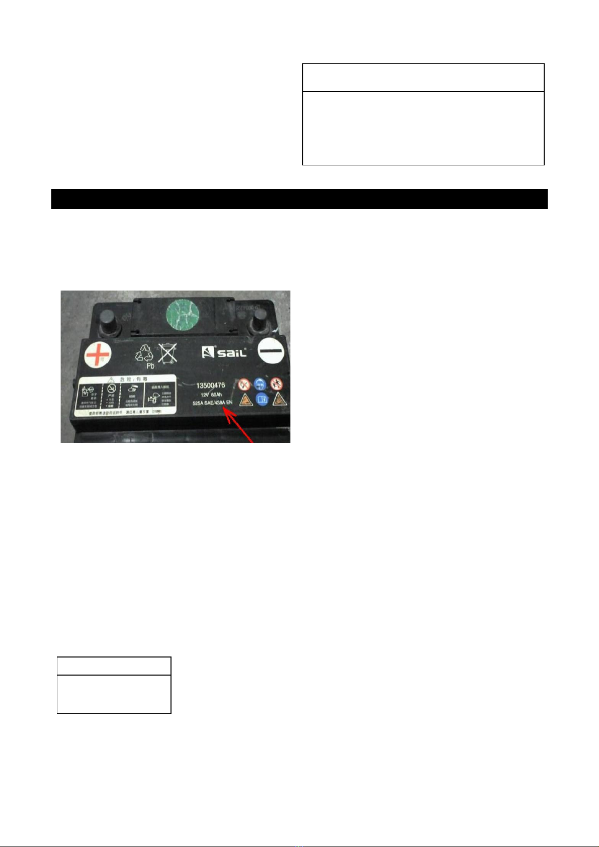
BATTERY SYSTEM STANDARD AND RATING
The SP61062 battery tester will test each battery according to the selected system and rating.
Use UP/DOWN key to select according to the actual system standard and rating marked on the
battery. Use UP/DOWN key to select according to the actual system standard and rating marked
on the battery. See in the below picture, the arrow indicated location.
•CCA: Cold Cranking Amps, specified by SAE&BCI, most frequently used value for starting
battery at 0°F (-18°C).
•BCI: Battery Council International standard
•CA: Cranking Amps standard, effective starting current value at 0°C
•MCA: Marine Cranking Amps standard, effective starting current value at 0°C.
•JIS: Japan Industrial Standard, displayed on the battery as combination of the numbers and
letters, e.g. 55D23,80D26.
•DIN: German Auto Industry Committee Standard
•IEC: Internal Electro technical Commission Standard
•EN: European Automobile Industry Association Standard
•SAE: Society of Automotive Engineers Standard
•GB: China National Standard
1. Regular Flooded
2. AGM Flat Plate
3. AGM Spiral
4. GEL
5. EFB
Battery Type
CCA
Select Input

10
RATING RANGE AS FOLLOWS
Measure Standard
Measure Range
CCA
100-2000
BCI
100-2000
CA
100-2000
MCA
100-2000
JIS
26A17--245H52
DIN
100-1400
IEC
100-1400
EN
100-2000
SAE
100-2000
GB
30Ah-220Ah
Input correct test standard and rating, press ENTER key, tester starts to
test, and dynamic interface "TESTING" prompted. See below:
It takes around 3 seconds to display the battery test result.
BATTERY TEST RESULT
Battery test result includes 5 types as following:
1. GOOD BATTERY
The battery is without fault, good to use.
2. GOOD RECHARGE
Good battery but low current, recharge before using.
500A CCA
Setting Rate
Condition: 96% 12.64V
Charge: 98% 490CCA
Internal R=6.1mΩ
Rated: 500A
GOOD BATTERY
Condition: 78% 12.20V
Charge: 30% 440CCA
Internal R=7.2mΩ
Rated: 500A
GOOD, RECHARGE

11
Start Engine
Cranking Test
3. REPLACE
The battery is near to or already reached the end of the
using life, replace battery.
4. BAD CELL, REPLACE
Battery interior damaged, bad cell or short circuit, replace
battery.
5. CHARGE, RETEST
Unstable battery shall be recharged and retested to avoid
error. If same test result appears after recharge and
retest, the battery is regarded as damaged, replace the
battery. Attention: If "Replace" resulted from IN-VEHICLE
mode, check the cable connections between the
alternator and the battery. If the tester still says to
REPLACE, disconnect and retest the battery under OUT-
OF-VEHICLE before making a decision to replace battery.
NOTE: After testing, if need to Exit, press EXIT key to directly Exit to the start up interface. After
testing: if it's "IN-VEHICLE" test state, press ENTER key will bring to Cranking Test.
CRANKING TEST
Tester prompts as following:
Starting the engine as prompted, tester will automatically
complete the cranking test and display the result.
Normally, cranking voltage value lower than 9.6V is
regarded as abnormal and it is normal if it is higher than
9.6V. Test result of the tester includes actual cranking
voltage and actual cranking time.
Condition: 46% 12.68V
Charge: 80% 490CCA
Internal R=18.1mΩ
Rated: 500A
REPLACE
Condition: 0% 10.64V
Charge: 20% 0CCA Internal
R=45.2mΩ
Rated: 500A
BAD CELL,REPLACE
Condition: 39% 12.08V
Charge:20% 310CCA
Internal R=30.1mΩ
Rated: 500A
CHARGE - RETEST
RPM Detected
Cranking Test
Time 780ms
Cranking Normal
10.13V
Cranking Test
12
When cranking test is abnormal, battery test result will
also be displayed at the same time.
This is for the convenience of the maintenance
personnel to quickly know the whole state of the
starting system according to the data.
After you have finished testing, do not shut down the
engine, press ENTER key to enter Charging Test.
CHARGING SYSTEM AND RECTIFIER DIODE TEST
When doing the charging test, please choose "Charging
Test".
Press ENTER key again to start the charging test.
NOTE: Do not shut down the engine during the test.
All electrical appliance and device are in OFF.
Turn off any electrical appliances in the vehicle during the
test as it will affect the accuracy of the test result.
TESTER WILL DO THE FOLLOWING TESTS IN SEQUENCE:
RIPPLE TEST
For ripple test, tester will display the real time ripple and
meanwhile, shows ripple volt and charging volt values at
the bottom line.
It takes approx. 6 seconds for the ripple test.
CHARGING TEST
After the ripple test, tester will automatically start the
loaded voltage test.
Loaded Volt Test takes approx. 3 seconds, then it hints
"Step on accelerator to increase engine rotation speed"
Operate accordingly to increase the engine rotating speed
to 2500rpm or above, and keep for 5 seconds.
Tester starts the charging volt test after it has detected a
increase in rpm.
Time 1020ms
Cranking Low
10.13V
Cranking Test
1. Battery Test
2. Cranking Test
3. Charging Test
Test In-Vehicle
95mV 14.32V
Ripple Test
Loaded Testing ****
Charging Test
Increasing RPM to
2500 r/min
And keep it 5
seconds.
Press OK to
continue.
Charging Test

13
After the test is finished, the tester displays the effective
charging volts, ripple test result and charging test result.
NOTE: If no increase in rpm is detected, it is the fault of
alternator regulator or the connection with the battery
has failed. Tester will try 3 times to detect, if still failed, it
will skip the increase rpm detect and the test result
displays "No Volt Output". See below:
Check the connection between alternator and battery, then retest.
Charging Test Result:
1. Charging Volt: Normal
Charging system shows the generator output normal, no problem detected.
2. Charging Volt: Low
Charging volt of the charging system is low.
Check drive belt of the alternator to see whether it is slipping or has run off.
Check the connection between alternator and battery.
If both of the drive belt and the connection are in good condition, follow the
manufacturer's suggestion to eliminate alternator fault.
3. Charging Volt: High
Alternator output volt is high.
Since most of the vehicle alternators use a internal regulator, the alternator
assembly has to be replaced.(Some old style cars are using external
regulator, then directly replace the regulator.)
The normal high volt of the voltage regulator is maximum 14.7±0.5V.If
charging volt is too high, it will overcharge the battery. Therefore the battery
life will be shortened and troubles will be caused.
4. No Volt Output:
No alternator volt output is detected. Check the alternator connection cable
and the belt whether they are in a sound condition.
5. Diode Test:
Through the test of charging current ripple, tester will find out whether the
diode is normal or not. When ripple volt is too high, it proves at least one
diode is damaged. Check and replace the faulty diode.
Loaded 14.16V
Unloaded 14.39V
Ripple 15mV
Charging Normal
Cranking Test
14
1. Battery In-Vehicle
2. Out Of-Vehicle
3. Review Data
4. Print Data
5. System Setup
Main Menu
BATTERY OUT-OF-VEHICLE TEST
The SP61062 battery tester activates once the clamps have been correctly connected and
automatically enters the battery test program. It will display the following content in a sequence,
select accordingly.
BATTERY OUT-OF-VEHICLE
Battery OUT-OF-VEHICLE means battery is not
connected to the vehicle at all.
Select UP/DOWN key to select the battery out
of vehicle. Then press the ENTER key to
confirm.
SELECT BATTERY TYPE
The tester will now prompt you to choose a
battery type, i.e. Regular Flooded, AGM Flat
Plate or AGM spiral, Gel and EFB battery.
Press the UP/DOWN key to select a battery
type, and then press the OK key to confirm.
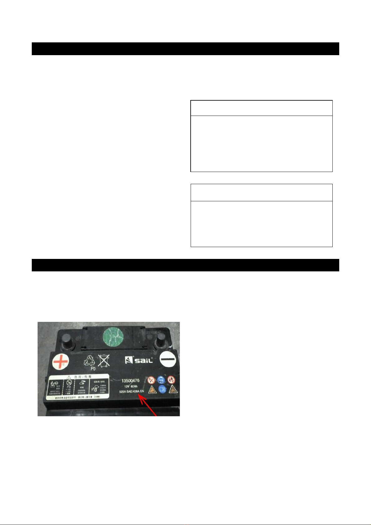
BATTERY SYSTEM STANDARD AND RATING
The SP61062 battery tester will test each battery according to the selected system and rating.
Use UP/DOWN key to select according to the actual system standard and rating marked on the
battery. Use UP/DOWN key to select according to the actual system standard and rating marked
on the battery. See in the below picture, the arrow indicated location.
•CCA: Cold Cranking Amps, specified by SAE&BCI, most frequently used value for starting
battery at 0°F (-18°C).
•BCI: Battery Council International standard
•CA: Cranking Amps standard, effective starting current value at 0°C
•MCA: Marine Cranking Amps standard, effective starting current value at 0°C.
1. Regular Flooded
2. AGM Flat Plate
3. AGM Spiral
4. GEL
5. EFB
Battery Type

15
•JIS: Japan Industrial Standard, displayed on the battery as combination of the numbers and
letters, e.g. 55D23,80D26.
•DIN: German Auto Industry Committee Standard
•IEC: Internal Electro technical Commission Standard
•EN: European Automobile Industry Association Standard
•SAE: Society of Automotive Engineers Standard
•GB: China National Standard
RATING RANGE AS FOLLOWS
Measure Standard
Measure Range
CCA
100-2000
BCI
100-2000
CA
100-2000
MCA
100-2000
JIS
26A17--245H52
DIN
100-1400
IEC
100-1400
EN
100-2000
SAE
100-2000
GB
30Ah-220Ah
Input correct test standard and rating, press ENTER key, tester starts to
test, and dynamic interface "TESTING" prompted. See below:
It takes around 3 seconds to display the battery test result.
CCA
Select Input
500A CCA
Setting Rate

16
BATTERY TEST RESULT
Battery test result includes 5 types as following:
1. GOOD BATTERY
The battery is without fault, good to use.
2. GOOD RECHARGE
Good battery but low current, recharge before using.
3. REPLACE
The battery is near to or already reached the end of the
using life, replace battery.
4. BAD CELL, REPLACE
Battery interior damaged, bad cell or short circuit, replace
battery.
5. CHARGE, RETEST
Unstable battery shall be recharged and retested to avoid
error. If same test result appears after recharge and
retest, the battery is regarded as damaged, replace the
battery.
Condition: 96% 12.64V
Charge: 98% 490CCA
Internal R=6.1mΩ
Rated: 500A
GOOD BATTERY
Condition: 78% 12.20V
Charge: 30% 440CCA
Internal R=7.2mΩ
Rated: 500A
GOOD, RECHARGE
Condition: 46% 12.68V
Charge: 80% 490CCA
Internal R=18.1mΩ
Rated: 500A
REPLACE
Condition: 0% 10.64V
Charge: 20% 0CCA Internal
R=45.2mΩ
Rated: 500A
BAD CELL,REPLACE
Condition: 39% 12.08V
Charge:20% 310CCA
Internal R=30.1mΩ
Rated: 500A
CHARGE - RETEST

17
REVIEW DATA
Select REVIEW DATA in the main menu
Check the history of battery testing result
PRINT DATA
Before choosing the print data function, it is necessary to connect the tool to the computer via
USB cable. Once all are available, please kindly insert the CD to the computer.
Install the USB driver
Then open the Print software
1.Battery in Vehicle
2.Out of Vehicle
3.Review Data
4. Print Data
5.System Setup
Main Menu
Condition: 96% 12.64V
Charge: 98% 490CCA
Internal R=6.1mΩ
Rated: 500A
GOOD BATTERY

18
Choose the COM Port NO.
If there is some history in print software, please clear it.
Choose the function of Print Data in the tool.
Once the data is transferred to the computer,
the print software will show this information.
After transferring the data to the computer, the tool
will automatically return to the main menu.
CLEANING AND MAINTENANCE
•Keep your Battery Analyser dry, clean and free from oil, water and grease.
•Use a mild detergent on a clean cloth to clean the outside of the tool, when necessary.
•Store the unit in a dry dust free environment.
DISPOSAL AND RECYCLING INFORMATION
When the tool reaches its end of life, take it to a collection point designated by local authorities
for E-waste.
The separate collection and recycling of your product at the time of disposal will help conserve
natural resources and ensure that it is recycled in a manner that protects human health and the
environment.
1.Battery in Vehicle
2.Out of Vehicle
3.Review Data
4. Print Data
5. System Setup
Main Menu
Condition: 96% 12.64V
Charge: 98% 490CCA
Internal R=6.1mΩ
Rated: 500A
GOOD BATTERY

19
LIMITED WARRANTY
This Limited Warranty applies only to new products* distributed by SP Tools Pty Ltd (“SP Tools”). It is a condition of this Limited
Warranty Policy that the purchaser read the owner’s manual for the product and only use the product to the extent or for the
purposes stated therein. The purchaser must also ensure that all servicing requirements are completed as listed in the owner’s
manual (said servicing is at the owner’s expense). We recommend that all servicing is completed by an authorised service agent and
that records of said servicing are retained by the purchaser as proof in the event of a warranty claim.
Whilst the owner’s manual, packaging, and/or other documentation supplied with SP Tools’ products may provide details in respect
of a Limited Warranty, the terms set out herein supersede these matters, and this Limited Warranty applies in their place. This
warranty is no less advantageous than otherwise described in such other documentation.
SP Tools agrees, subject to the terms and conditions specified below, to repair or replace at SP Tools’ cost, the product purchased by
you when the product does not perform in accordance with its specifications during the limited warranty period, due to any fault in
manufacturing, materials and/or workmanship. SP Tools is not liable to repair or replace products that the purchaser uses in a
manner that is inconsistent with the owner’s manual or in the circumstances set out in paragraphs 1.1 – 1.7 below.
The benefits to the purchaser under this warranty are in addition to other rights and remedies under the Competition and Consumer
Act 2010 (Cth). The limited warranty period, within which a defect in the product must appear, commences from the date of
purchase and ceases on expiration of the specified term below.
THE LIMITED WARRANTY PERIOD
• SP Speciality Tools –12 Months
THE PURCHASERS ATTENTION IS DRAWN TO THE FOLLOWING
To the extent permitted by law and subject to this Limited Warranty, and as part of the terms of the sale of the equipment or part
thereof: SP Tools shall not be liable for any form of loss, damage, cost, injury or harm of any kind (whether direct, indirect, special
or consequential) howsoever arising from the use or supply of the equipment to the purchaser.
EXCLUSIONS TO LIMITED WARRANTY POILICY
This Limited Warranty will not apply where the equipment or any part thereof:
1.1 Fails due to an accident (including liquid spillage), abuse, misuse, neglect or normal wear and tear;
1.2 Has been used in a manner other than for which it was originally designed;
1.3 Has been tampered with or is otherwise than as supplied by SP Tools;
1.4 Where any damage, malfunction or other failure of the equipment or any part thereof resulted directly or indirectly from
unauthorized persons, adjusting or failing to adjust any part requiring normal maintenance and service (examples include
adjustment of tappets, air filter maintenance, lubrication and tightening of screws nuts and bolts);
1.5 Malfunctions due to the use of defective or incompatible accessories;
1.6 Is damaged by lightning or thunderstorm activity; or
1.7 Has been transported to a country where no authorised Service Agents exist.
CLAIMING WARRANTY
This Limited Warranty may be claimed on in the following manner:
2.1 In order to make a claim under this Limited Warranty, the purchaser must deliver the equipment or any part thereof to an
SP Tools authorised repair agent and pay all costs of transportation and all costs incidental to making a claim under
this Limited Warranty. The purchaser must first contact SP Tools (contact details described above) and request the
delivery address of an SP Tools authorised repair agent.
2.2 The purchaser must deliver to the repair agent written reasons why the purchaser considers that the purchaser has a claim
under this Limited Warranty and must provide all necessary details, including:
•The place, date and from whom the unit or part was purchased.
•The unit or part involved, Model and Serial Number.
•The defect, malfunction or failure in respect of which the claim is being made.
•Proof of service of the unit or part (if applicable)
•Proof of purchase in respect of the unit or part.
2.3 If the Limited Warranty claim is valid, the repair agent will carry out repairs and return the product at no charge to the
purchaser. These repairs are limited to the Limited Warranty fault identified and as such will not include any other faults due to
misuse, abuse, failure to maintain, fair wear and tear or the replacement of serviceable items such as oil, spark plugs, air filters,
fuel etc.
Our goods come with guarantees that cannot be excluded under Consumer Law. You are entitled to a replacement or refund for a
major failure and for compensation for any other reasonably foreseeable loss or damage. You are also entitled to have the goods
repaired or replaced if the goods fail to be of acceptable quality and the failure does not amount to a major failure.
Note: Units which are failing to perform in accordance with specifications due to non-warrantable causes will be subject to freight,
repair and or quote charge
Table of contents
Other SP tools Test Equipment manuals

Popular Test Equipment manuals by other brands


DATREND Systems
DATREND Systems vPad-RW operating manual

TESTO
TESTO 549 instruction manual

Q3 Innovations
Q3 Innovations AlcoHAWK PT500 owner's manual

Honeywell
Honeywell Posi 3 Setup guide

Vanguard Instruments
Vanguard Instruments VBT-75P S2 user manual

Brütsch Rüegger
Brütsch Rüegger MITUTOYO SURFTEST SJ 201P manual


