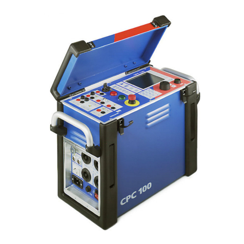
Omicron CPC 100 User manual

Preface Introduction Quick Current
transformer
Voltage
transformer
Transformer Resistance Others Common
functions
Technical data CP TD CP CU1 CP SB1 CP CB2
Manual information
Article Number VESD0601 - Manual Version: ENU 1036 05 07
© OMICRON electronics 2019. All rights reserved.
This product includes software developed by Intrinsyc Software.
This manual is a publication of OMICRON electronics GmbH.
All rights including translation reserved. Reproduction of any kind, for example, photocopying,
microfilming, optical character recognition and/or storage in electronic data processing systems,
requires the explicit consent of OMICRON. Reprinting, wholly or in part, is not permitted.
The product information, specifications, and technical data embodied in this manual represent
the technical status at the time of writing and are subject to change without prior notice.
We have done our best to ensure that the information given in this manual is useful, accurate
and entirely reliable. However, OMICRON does not assume responsibility for any inaccuracies
which may be present.
The user is responsible for every application that makes use of an OMICRON product.
OMICRON translates this manual from the source language English into a number of other
languages. Any translation of this manual is done for local requirements, and in the event of a
dispute between the English and a non-English version, the English version of this manual shall
govern.
Support
When you are working with our products we want to provide you with the greatest possible
benefits. If you need any support, we are here to assist you!
24/7 Technical support – get support
www.omicronenergy.com/support
At our technical support hotline, you can reach well-educated technicians for all of your
questions. Around the clock – competent and free of charge.
Make use of our 24/7 technical support hotlines:
Americas: +1 713 830-4660 or +1 800-OMICRON
Asia-Pacific: +852 3767 5500
Europe / Middle East / Africa: +43 59495 4444
Additionally, you can find our Service Center or Sales Partner closest to you at
www.omicronenergy.com.
Customer area – stay informed
www.omicronenergy.com/customer
The customer area on our website is an international knowledge exchange platform. Download
the latest software updates for all products and share your own experiences in our user forum.
Browse through the knowledge library and find application notes, conference papers, articles
about daily working experiences, user manuals and much more.
OMICRON Academy – learn more
www.omicronenergy.com/academy
Learn more about your product in one of the training courses offered by the OMICRON
Academy.
CPC 100
User Manual
OMICRON electronics GmbH, Oberes Ried 1, 6833 Klaus, Austria, +43 59495

CPC 100 User Manual
Preface - 1
Since the scope of this User Manual is confined to the most important information about a
specific subject, the CPC 100 User Manual complements the CPC 100 Reference Manual,
however, it does not replace it. The CPC 100 Reference Manual is available in PDF format on
the Primary Test Manager DVD and the CPC 100 Start Page.
Reading the CPC 100 User Manual alone does not release the user from the duty of complying
with all national and international safety regulations relevant for working with the CPC 100, for
example, the regulation EN50191 “Erection and Operation of Electrical Test Equipment” as well
as the applicable regulations for accident prevention in the country and at the site of operation.
Conventions and symbols used
In this manual, the following symbols indicate safety instructions for avoiding hazards.
The CPC 100 must be used in observance of all existing safety requirements from national
standards for accident prevention and environmental protection. Before operating the CPC 100,
read the following safety instructions carefully. Do not turn on or use the CPC 100 if you do not
understand the information in this manual. If any of the safety instructions are unclear, contact
OMICRON.
Principle use according to regulations
►Use CPC 100 and its accessories only in a technically sound condition.
► Make sure its use is in accordance with the regulations on site and the designated use
described in this document.
► Comply with the workflows described in this document. Avoid interruptions or distractions
that could affect safety.
►TheCPC 100 is exclusively intended for the application fields specified in detail in
”Designated use” on page Preface-2. The manufacturer/distributor is not liable for damage
resulting from improper usage.
► Follow the instructions provided in this User Manual and in the CPC 100 Reference Manual
available in PDF format on the Primary Test Manager DVD and the CPC 100 Start Page.
► Do not open the CPC 100 housing.
► If you do not use the CPC 100 anymore, turn the key to “lock” (vertical) and remove the key
to avoid anybody accidentally turning on the CPC 100.
► Store the key and the CPC 100 separately to prevent unauthorized personnel from using the
CPC 100.
► If you have a cardiac pacemaker, do not use the CPC 100.
Before operating the CPC 100, make sure there is no person with a cardiac pacemaker in
the immediate vicinity.
Orderly measures
► This User Manual only complements the CPC 100 Reference Manual available in PDF
format on the Primary Test Manager DVD and the CPC 100 Start Page. However, it does
not replace it.
► Either this User Manual or the CPC 100 Reference Manual should always be available on
the site where the CPC 100 is being used.
► Personnel assigned to use the CPC 100 should carefully read the CPC 100 User Manual/
Reference Manual - in particular the section on safety instructions - before beginning to work
with it. On principle, this also applies to personnel who only occasionally work with the
CPC 100.
► Do not undertake any modifications, extensions, or adaptations to the CPC 100.
► Use the CPC 100 in conjunction with original accessories only.
Operator qualifications and primary responsibilities
Only authorized personnel who are qualified, skilled and regularly trained in electrical
engineering are allowed to operate the CPC 100 and its accessories. Personnel receiving
training, instructions, directions, or education on CPC 100 must be under constant supervision
of an experienced operator while working with the equipment. The supervising operator must be
familiar with the equipment and the regulations on site.
Safe operation
If the equipment is used in a manner not described in the user documentation, the protection
provided by the equipment may be impaired.
When putting the CPC 100 into operation, follow the instructions in section “Putting CPC 100
into Operation” in the CPC 100 Reference Manual (available in PDF format on the
Primary Test Manager DVD or the CPC 100 Start Page).
► Never use the CPC 100, any accessory or the CP TD equipment trolley without a solid
connection to earth with at least 6 mm².
► Use a ground point as close as possible to the operator.
DANGER
Death or severe injury will occur if the appropriate safety instructions are not
observed.
WARNING
Death or severe injury can occur if the appropriate safety instructions are not
observed.
CAUTION
Minor or moderate injury may occur if the appropriate safety instructions are not
observed.
NOTICE
Equipment damage or loss of data possible
About this user manual Safety instructions for the CPC 100 and its accessories
Preface
CPC 100 User Manual
Preface - 2
Preface
The CPC 100, in conjunction with its accessories or as a stand-alone unit, is a multi-purpose
primary test set for commissioning and maintaining substation equipment. It performs current
transformer (CT), voltage transformer (VT) and power transformer (TR) tests. Furthermore, it is
used for contact and winding resistance testing, polarity checks as well as primary and
secondary protection relay testing.
The various, partly automated tests are defined and parameterized via the front panel control of
a built-in embedded PC.
The functionality scope of the CPC 100 is described in detail in the chapter “Designated Use” of
the CPC 100 Reference Manual available in PDF format on the Primary Test Manager DVD or
the CPC 100 Start Page.
Note: Any other use of the CPC 100 but the one mentioned above is considered improper use,
and will invalidate all customer warranty claims and exempt the manufacturer from any liability
to recourse.
Example of the separation of work area and high-voltage area using different OMICRON
devices:
► Do not enter the high-voltage if the red status light of the CPC 100 is on.
Safety symbols on the device
General
The CPC 100’s outputs and the cables connected to them carry life-hazardous voltage or
current.
► Always obey the five safety rules and follow the detailed safety instructions below.
► Before connecting or disconnecting test objects and/or cables, turn off the CPC 100 by
pressing the POWER ON/OFF switch. Then press the Emergency Stop button.
► Never connect or disconnect a test object while the outputs are active.
► Make sure that a test object’s terminals that are to be connected to the CPC 100 do not carry
any voltage potential. During a test, the only power source for a test object may be the
CPC 100.
► At their output sockets and especially in the cables connected to them, in operation the high-
current outputs 400A DC and 800A AC generate a significant amount of heat (approx.
300W/m at 800A). To prevent burns, use gloves when touching the cables while in
operation or a short while after.
► Do not insert objects (e.g., screwdrivers, etc.) into any input/output socket.
► Never use the test cards Quick and Resistance to measure the resistance of windings with
a high inductance because turning off the DC source results in life-threatening voltage
levels. For this kind of measurement only use either the special winding resistance test card
RWinding or the test card TRTapCheck.
► When measuring the ratio of voltage and power transformers make sure that the test voltage
is connected to the corresponding high-voltage winding, and the voltage of the low-voltage
winding is the one that is measured. Accidentally mixing up the windings can generate life-
threatening voltages within the transformer.
FOR YOUR OWN SAFETY
Always follow the 5 safety rules:
1. Disconnect completely.
2. Secure against re-connection.
3. Verify that the installation is dead.
4. Carry out grounding and short-circuiting.
5. Provide protection against adjacent live
parts.
CP GB1
CP CR500
CP SB1
CP CU1
CP TD1
CPC 100
CPC 100
High-voltage area
Device under test
2 kV AC, 130 V AC
outputs
Work area
Caution, possibility of electric shock
Caution
Designated use Safety instructions for the CPC 100 and its accessories

CPC 100 User Manual
Preface - 3
► Make sure that when testing a current transformer by feeding a test current into its primary
winding, all secondary windings are shorted. On open secondary windings, life-threatening
voltages can be induced.
► Connect only one CPC 100 output at a time.
► All AC and DC output sockets of the CPC 100 can carry life-hazardous voltage potential and
provide life-hazardous currents. Therefore:
► While connecting cables to the CPC 100 high-voltage or current outputs, or other
conducting parts that are not protected against accidental contact, press the Emergency
Stop button, and keep it pressed as long as an output signal is not absolutely necessary
for the test.
► When connecting to the front panel input/output sockets, use wires with either 4 mm
safety “banana” connectors and plastic housing or, where applicable, with the especially
manufactured counterpart supplied by OMICRON (e.g., for the V2 AC measuring input).
► For the high-voltage and current output connectors on the left-hand side of the test set
(2kV AC, 400A DC and 800A AC, Ext. Booster), only use the specially manufactured
cables supplied by OMICRON (refer to the chapter “Accessories” of the CPC 100
Reference Manual available on the Primary Test Manager DVD or the CPC 100
Start Page).
► One end of the high-voltage cable has a coaxial safety plug that is certified for a voltage
level of 2kV AC. The other end is equipped with a safety banana plug that is insulated
with a shrink tube. When the CPC 100 is switched on, consider this part of the cable a
hazard of electric shock.
► If you do not use the high-current outputs 400A DC or 800A AC, or the high-voltage
output 2kV AC, disconnect any cable that may be plugged in to these sockets.
Note: The 400A DC or 800A AC outputs are not switched off by internal relays. Therefore,
if a test mode is selected that does not use either one of these two outputs, they still
generate current.
► Do not stand right next to or directly underneath a connection point because the clamps may
fall off and touch you.
► The red status light on the CPC 100 front panel indicates hazardous voltage and/or
current levels at the CPC 100 outputs (red light “I” on or flashing). The green status light
indicates that the CPC 100 outputs are not activated.
Note: If none or both status lights are on, the unit might be defective. Contact
OMICRON Support.
► Both of the high-current output sockets on the left-hand side of the test set (400A DC
and 800A AC) usually carry a relatively low-voltage potential. However, in case of an
internal insulation fault these outputs may carry up to 300 V. Consider these outputs life-
hazardous.
► Always lock connectors properly.
► The high-current cables for both the 800A AC and 400A DC outputs are equipped with
connection clamps at one end. If these connection clamps are attached to a test object’s
terminal that is situated above your head, make sure the clamp is securely attached. Due to
the weight of the cables the clamp may become loose and fall down.
► Do not operate the CPC 100 under ambient conditions that exceed the temperature and
humidity limits listed in ”General” on page Technical Data-3.
► Do not operate the CPC 100 in the presence of explosives, gas or vapors.
► If the CPC 100 or any add-on device or accessory does not seem to function properly, do
not use it anymore. If in doubt, contact OMICRON Support. (refer to cover page of this User
Manual).
Grounding
Operating the device without PE and ground connection is life-threatening and not permitted.
► Only operate the CPC 100 with a mains power supply connected to protective earth (PE).
► Make sure that both the PE connection of the power supply and the ground connector of the
CPC 100 have a solid and low-impedance connection to the grounding system on site.
This also applies to all other test devices and accessories in the test setup.
► Make sure that the grounding clamp has a good electrical contact to the grounding system
on site and avoid connecting it to corroded or painted surfaces.
► Make sure that the grounding terminal connections of all grounded devices in use remain
intact during the whole measurement procedure, and are not accidentally disconnected.
Only use ground and supply cables provided by OMICRON.
The counterpart of the high-current sockets are locking connectors.
To lock these connectors safely, insert them carefully until you feel a
“click” position. Now they are locked. Confirm this by trying to pull them
out. This should not be possible now.
To remove the locking connectors, unlock them by pushing them in
completely first, and then pull them out.
Safety Instructions for the CPC 100 and its accessories

CPC 100 User Manual
Preface - 4
Preface
Power supply
Operating the CPC 100 without PE and ground connection is life-threatening and not permitted.
► Only operate the CPC 100 with a mains power supply connected to protective earth (PE).
Power supply from grounded grids (TN/TT)
Before a measurement is started, the CPC 100 automatically verifies the PE connection in
grounded grids (TN/TT).
► If this check fails, check the power cord and power supply.
If the error message persists, there is no intact connection to protective earth (PE).
This is life-threatening. In this case measurements are not permitted and cannot be performed.
Power supply from isolated grids (IT)
An IT grid is a grid structure where none of the active conductors are galvanically connected to
ground. In an IT grid, only the PE is connected to ground.
In IT grids, the check fails – even if there is a PE connection. This can be the case when the
CPC 100 is powered by a generator. Since every operation mandates a PE connection for the
operation of the CPC 100, you need to manually verify this.
If the CPC 100 is supplied by a generator, the equipotential ground or PE of the generator has
to be grounded properly.
► If this is not possible, measurements are not permitted and cannot be performed.
Additional information
Instead of supplying the CPC 100 from phase-neutral (L1-N, A-N), it may also be supplied from
phase-phase (for example, L1-L2; A-B).
► Make sure that the voltage does not exceed 240V AC.
► Make sure that the power supply is fuse-protected (16 A automatic circuit breaker).
► Do not use an extension cable on a cable reel to prevent an overheating of the cord; run out
the extension cord.
► Keep extension cables as short as possible to prevent power loss.
If the power supply is ≤ 190V AC, the CPC 100 cannot provide the full output power at the
800A AC output. The same applies when an external current booster is used.
► Therefore, in order to gain the full output power, provide a sufficient power supply
(190 V ... 240 V AC).
The Ext. Booster connector is always galvanically connected to mains and active.
This also applies when no external booster is selected, the green status light (0) is on, the
outputs are turned off, or the Emergency Stop button is pressed.
► Handle the Ext. Booster connector with extreme caution.
► Only use booster cables supplied by OMICRON.
► Do not use booster cables that are frayed or damaged in any way.
Changing fuses
1. Ground the test object, and disconnect it from the CPC 100. By disconnecting it, you prevent
a possibly faulty test object feeding power back into the CPC 100.
2. Turn off the CPC 100 and unplug the power cord. Then press the Emergency Stop button.
Wait for about 30 seconds. This time is necessary for the internal electrolytic capacitors to
fully discharge.
3. Locate the blown fuse on the front panel of the CPC 100, and replace it.
Note: Replace with identical fuse type only (refer to the chapter “Changing Fuses” of the
CPC 100 Reference Manual available in PDF format on the Primary Test Manager DVD or the
CPC 100 Start Page).
DC output to test objects with a high inductance
► Only use the dedicated test cards for DC measurements on assets with inductive
characteristics:
► Never open the measuring circuit while current flows.
► After a measurement, wait until the test device has discharged completely.
► Ground all terminals of the test object before touching the test setup.
CPC 100 test cards Primary test manager tests
RWinding DC Winding Resistance
D-OLTC-Scan Dynamic OLTC Scan
Demagnetization Demagnetization
TRTapCheck CT Winding Resistanc Sec
DC Winding Resistance Stator
DC Winding Resistance Rotor
Safety Instructions for the CPC 100 and its accessories

CPC 100 User Manual
Preface - 5
► Short-circuit the terminals before disconnecting the test leads.
► Disconnect cables not used for testing both from the test object and the test device.
Discharging after tests on objects with a high inductance
After a winding resistance measurement, the CPC 100 monitors the reduction of the current and
voltage levels to zero. During this discharge process, the red status light flashes.
In the Demag test card, the discharging process is displayed as a status message
(see "Demagnetization" on page 10).
Note: When you disconnect a cable during the discharge process, even low voltage presents
considerable danger as it suddenly increases to a very high level when the circuit is
disconnected.
► Do not touch or disconnect any part of the test setup until the current and voltage levels have
reduced to zero.
► If the measurement is interrupted due to, for example, an unexpected loss of supply voltage
or erroneous behavior of the CPC 100 do not touch the test setup until the energy has
dissipated over time.
Note that the length of time depends heavily on the asset under test.
CPC 100 in combination with the CP TD
The CP TD (CP TD1, CP TD12 and CP TD15) is an optionally available high-precision test
system for on-site insulation tests of high-voltage systems like power and measuring
transformers, circuit breakers, capacitors and isolators. The CP TD works as an add-on device
to the CPC 100 and is described in chapter ”CP TD” of this User Manual.
On principle, the safety instructions that apply to the CPC 100 and its accessories also apply to
the CP TD. However, the CP TD requires some additional precautions and measures. They are
listed in chapter ”CP TD” on page CP TD1-1.
In all other affected tests, the
discharge progress is displayed in a
dialog.
LED steady-on red: voltage on 6A DC output > 2 V
Note: This indicator only applies to the 6A DC output and
does not include the 400A DC output.
Safety Instructions for the CPC 100 and its accessories

CPC 100 User Manual
Preface - 6
Preface
Declaration of Conformity (EU)
The equipment adheres to the guidelines of the council of the European Community for meeting
the requirements of the member states regarding the electromagnetic compatibility (EMC)
directive, the low voltage directive (LVD) and the RoHS directive.
FCC Compliance (USA)
This equipment has been tested and found to comply with the limits for a Class A digital device,
pursuant to part 15 of the FCC Rules. These limits are designed to provide reasonable
protection against harmful interference when the equipment is operated in a commercial
environment. This equipment generates, uses, and can radiate radio frequency energy and, if
not installed and used in accordance with the instruction manual, may cause harmful
interference to radio communications. Operation of this equipment in a residential area is likely
to cause harmful interference in which case the user will be required to correct the interference
at his own expense.
Changes or modifications not expressly approved by the party responsible for compliance could
void the user's authority to operate the equipment.
Declaration of Compliance (Canada)
This Class A digital apparatus complies with Canadian ICES-003.
Cet appareil numérique de la classe A est conforme à la norme NMB-003 du Canada.
Cleaning
► Do not clean CPC 100 or any other device when connected to the test object.
► Disconnect the test object, accessories and connection cables before cleaning.
► Use a cloth dampened with isopropanol alcohol to clean CPC 100 and its accessories.
This test set (including all accessories) is not intended for household use.
At the end of its service life, do not dispose of the test set with household
waste!
For customers in EU countries (incl. European Economic Area)
OMICRON test sets are subject to the EU Waste Electrical and Electronic
Equipment Directive 2012/19/EU (WEEE directive). As part of our legal
obligations under this legislation, OMICRON offers to take back the test set and
ensure that it is disposed of by authorized recycling agents.
For customers outside the European Economic Area
Please contact the authorities in charge for the relevant environmental
regulations in your country and dispose the OMICRON test set only in
accordance with your local legal requirements.
Declaration of Conformity Recycling

CPC 100 User Manual
Introduction - 1
Navigation
elements
AC OUTPUT
6A, 3A or 130V output
IAC/DC INPUT
Fuse-protected with a 10A very quick-acting fuse
Fuse 3.15A (slow-acting wire fuse 5x20 mm)
for 3A AC and 130V AC
Fuse 6.3A T (slow-acting wire fuse 5x20 mm)
for 3A AC, 6A AC, 130V AC and 6A DC
BIN IN
Binary trigger input, wet or dry contact
Key lock
Locks front panel operation.
V2 AC input
3V AC input
V1 AC input
300V AC input
VDC INPUT
10V DC input or 2-wire resistance
Emergency Stop button
Immediately shuts off all outputs (could leave transformer in
saturation).
Soft-touch
keyboard
I / 0 status lights
Status lights that indicate the operational status of the CPC 100 outputs. The green light "0" indicates that the current/voltage source is off while the red light "I" indicates that the current/voltage source is active and/or a measurement process is running.
Add test cards
We recommend not to use more than 15 test cards or 50 test
results in one test procedure.
Tab selector
To change between the single test cards of a test procedure.
Test Card View: View to set up test cards,
compose test procedures, enter test settings,
define test cards or the test procedure default, start
tests etc.
Test Procedure Overview: Provides an
enhanced overview of all test cards of the currently
active test procedure. Defines the test procedure
default.
File Operations: Lets you save, load, delete, copy
and rename test procedures.
Options: To specify general parameters.
I/O
Use to start and stop a test.
Context-dependent menu keys
Directly invoke specific commands associated with the
currently selected control of the test card and view.
DC OUTPUT
6A DC output (fuse-protected with a 6A fuse)
Functional components of the CPC 100
Introduction

CPC 100 User Manual
Introduction - 2
Introduction
Emergency Stop button
Pressing the Emergency Stop button immediately shuts off all current and voltage outputs
except for the Ext. Booster output.
A running test is terminated, the software does not accept any more entries and/or commands.
Once the reason for the Emergency Stop is cleared and the Emergency Stop button released,
the test can be re-started by pressing the I/O (test start/stop) push-button while in Test Card
View.
High-voltage and current outputs
When the CPC 100 outputs high current, observe the allowed duty cycles that may apply to the
selected AC output range.
ePC interfaces1
1. For detailed information on the RJ45 connectors, see chapter “CPC 100 in a Network” in the
CPC 100 Reference Manual available in PDF format on the CPC 100 Toolsets or CPC 100
Start Page.
2. For the pin assignment of the RS232 serial interface plug, refer to the CPC 100 Reference
Manual, section “ePC Interfaces” of chapter “Technical Data”.
3. The connector for external safety functions allows connecting safety accessories for the
CPC 100. The attached plug contains a jumper, and as long as it is placed on the connector,
the circuit is bridged. If the plug is removed, the emergency stop is active.
For the plug’s pin assignment and a wiring scheme, refer to section “Connector for External
Safety Functions” of chapter “Technical Data” in the CPC 100 Reference Manual.
DANGER
Death or severe injury caused by high voltage or current
The Ext. Booster connector is always galvanically connected to mains.
► Handle the Ext. Booster connector with extreme caution.
► Do not use any other booster cables than the ones supplied by OMICRON
electronics.
► Do not use booster cables that are frayed or damaged in any way.
WARNING
Death or severe injury caused by high voltage or current possible
Stopping a test does not shut off the CPC 100 outputs instantaneously. First, the
currently running test sequence finishes, then the test execution is stopped.
Most test cards finish the running test sequence with a predefined ramp function.
► Therefore, in a hazardous situation never press "Stop Test".
► Instead, use Emergency Stop.
800A AC
(6.1-6.5V AC)
High AC current
output
POWER ON /OFF
switch
Mains power supply,
1 phase, 85V-264V AC
2kV AC
High-voltage
output
400A DC
(4-4.5V DC)
High DC current output
Ext. Booster
e.g., for the
connection of the
CP CB2 current
booster option for
output currents of
up to 2000A
Grounding
terminal
Automatic circuit
breaker I > 16A
Reference point
1. Older CPC 100 versions have slightly different ePC interfaces. For detailed information refer to
the CPC 100 Reference Manual.
Serial interface
connector for
connecting optional
CP TD test set
RJ45 socket for connecting CPC 100 to a PC
or a network hub USB connector for connecting OMICRON
electronics USB memory sticks
Connector for external safety functions Red LED Green LED
Functional components of the CPC 100

CPC 100 User Manual
Introduction - 3
Test cards
The CPC 100 software comprises a number of test cards. A test card carries out one specific
test, e.g., measuring a CT excitation curve, or testing the ratio of a voltage transformer.
A test card holds a number of user-definable test settings and - after the test was run - test
results.
Test procedure
A test procedure contains multiple test cards.
The composition of such a test procedure and the settings of all single test cards can be freely
defined by the user. Within a test procedure, each test card and its associated test is executed
individually in a user-defined order.
Report
For archiving or reporting purposes, or later processing, a test procedure with all of its test cards,
specific settings and - after the test was run - test results and assessments can be saved. It is
then considered a report.
Such a report can later be opened any time in the CPC 100’s File Operations menu.
Note: For detailed information about test cards, test procedures and templates, refer to section
“How to Use The CPC 100 Software” of chapter “Introduction” in the CPC 100 Reference
Manual available in PDF format on the CPC 100 Toolsets or CPC 100 Start Page.
+
Rectifier
& power
factor
corrector
Filter
Switched
mode
amplifier
500V 4A
1kV 2A
2kV 1A
500V
500V
500V
500V
65V
65V
3.15A
6.3A
ADC
I
U
U
U
U
I
I
DSP
(Digital
Signal
Processor)
Built-in
ePC
Ethernet
RS 232
optional
optional interfaces
(plug-in boards)
analog or digital
2kV
800A
R
R
-
+
5V / 400A DC
10A AC/DC
3V AC
300V AC
10V DC
BIN IN
65V / 6A DC
6V / 800A AC
2kV
Ext.
Booster
130V / 6A AC
Mains
100-240V
50/60Hz
to
ext.
PC
I
n
p.
O
u
t
p
u
t
s
L
N
PE
Pressing the Settings menu key opens the Settings page (see page Quick-1) allowing you to
set the test cards individually. As a rule, do not set the test cards on the Settings page but set
all test cards of a test procedure using the Device Setup tab in the Options view (see page
Introduction-5).
The actual function of the context-dependent menu
keys depends on the selected view, test mode, test
card and selected test card component (i.e., the
focus).
Focus on the data entry field for AC current.
The term “focus” designates the currently selected (active) part of the test card. The selected
component is highlighted or inverted.
Status of test assessment. The test
assessment is a manual procedure carried
out by the user. After the test, set the focus
on the assessment symbol. Use the context-
dependent menu key OK or Failed to assess
the test.
For a few seconds, the status line also
displays general operation information, e.g.
“Emergency key pressed”.
Temperature and power consumption monitoring.
If an output is activated, both the CPC 100’s power
consumption and the current emitted at the high-
current outputs is monitored and, together with the
temperature, displayed by this temperature gauge.
The temperature gauge’s bar therewith represents
an indicator for the remaining time the CPC 100 can
output power.
plenty of spare
no more spare
CPC 100 block diagram Principles of test cards and test procedures The components of a test card

CPC 100 User Manual
Introduction - 4
Introduction
The Test Procedure Overview lists all test cards of the currently active test procedure in a list
box showing the card’s name, its creation date and time, whether test results are available and
the test card’s assessment status.
Note: For detailed information refer to section “Test Procedure Overview” of chapter
“Introduction” in the CPC 100 Reference Manual available in PDF format on the
CPC 100 Toolsets or CPC 100 Start Page.
The highest hierarchical level of the CPC 100 file system, the “root”, is named CPC 100. Below
this, you can create additional folders in a tree-structure of your choice, save tests in these
folders, and perform file operations, such as open, save, rename, copy, paste etc.
The CPC 100 file system differentiates two file types:
Note: The file containing the up-to-date measurements should be saved regularly. If the test unit
is switched off, or in case of a power outage, all unsaved measurements will be lost.
► Long-press the File operations button to save the currently open test.
Navigating through the file system
Select a test or a folder using the handwheel or the Up / Down keys. To expand a collapsed
folder tree , select it and press either the handwheel or Enter.
The menus
Main file operations menu
With Save As Default, Test Procedure Overview provides a function to save the
current test procedure as the test procedure default, i.e., that default the CPC 100
software will start with in future. name.xml A test procedure with all of its test cards and specific settings. An .xml file
may also contain test results and assessments that were stored together
with the settings as report in the CPC 100 file system for archiving
purposes.
name.xmt Test procedure template, i.e., a user-defined template containing one or
more test cards with all of their specific test settings but without test
results.
Opens the submenu File (refer to “Submenu File” on page 5)
Opens the submenu Edit (refer to “Submenu Edit” on page 5)
Saves the currently open test, i.e., the test card(s) previously opened in the Test
Card View (refer to Note below).
Opens the String Editor. You can save the currently open test under a new name
of your choice (15 characters max.).
Use the handwheel or the Up / Down keys to select a test, and press Open to open
it. Changes to Test Card View.
Closes the current test card(s), changes to Test Card View and opens the test
procedure default.
Test procedure overview The CPC 100 file system

CPC 100 User Manual
Introduction - 5
Note: Unlike the other menu items, the two Save…functions of the main File Operations menu
directly effect the currently open test, i.e., the test procedure that was composed in the Test
Card View, or the test that was loaded in the CPC 100 file system beforehand.
Therefore, pressing Save, for example, does not save the test that you may have highlighted in
the folder tree, but the one that is currently open.
Submenu File
Submenu Edit
Note: If a folder is cut or copied to the Clipboard, the selection is recursive, i.e., all of its
subfolders will also be put to the Clipboard.
Cutting or copying a test or folder, and trying to paste it in the same location, opens the String
Editor.
Since a test or folder cannot exist twice under the same name at the same location, determine
a new name for it using the String Editor.
Device setup
Opens the String Editor. You can create a new folder with any name of your choice.
Appends the contents of a test file (.xml) or template (.xmt) of your choice to the
currently open test.
Deletes the currently selected test or folder from the CPC 100’s disk space.
Opens the String Editor that enables you to rename the current test to any new
name of your choice.
(for future use)
Closes the submenu and returns to the main File Operations menu.
Select the test of your choice. Press Cut to put the selected test or folder to the
Clipboard. Proceed with Paste…
Select the test of your choice. Press Copy to copy test or folder to the CPC 100
clipboard. Proceed with Paste…
Move to the destination folder of your choice. Press Paste to insert the contents of
the CPC 100 clipboard to this folder.
Press Paste As Templ. to make the contents of the CPC 100 clipboard a test
procedure template.
(for future use)
Closes the Edit submenu and returns to the main File Operations menu.
Set the external booster you
want to use.
Set current clamp
parameters and CT and/or
VT transformation ratio.
Set the default frequency.
This value will be used for all
test cards.
Auto save automatically
saves the current test
settings in fixed intervals
specified to a file named
lastmeas.xml.Resets all user-specific settings made in the
CPC 100 software to factory-defined defaults
including:
• the test card defaults
• the test procedure default
• all settings made at the Device Setup tab
(Sets external booster to CB2, sets CT and
VT to “OFF” and sets the default frequency
to 50 Hz.)
• the String Editor’s template strings
If selected, the CPC 100 cools down faster.
Thus, the duty cycle can be increased.
The CPC 100 file system The Options menu

CPC 100 User Manual
Introduction - 6
Introduction
Network
Set the communication parameters.
Display
Accessories
The Accessories tab comprises safety-relevant settings for the CP TD. The settings you
choose in this view serve as a default for all corresponding test cards you set up afterwards.
Note: Per default and after start-up, the check boxes are activated.
2. Perform shield check
The shield check verifies if both the high-voltage connector and the grounding terminal are
connected to the CP TD. In certain cases, for example when strong interferences are present
during testing or when compensating reactors (e. g. the CP CR500) are used, the shield check
will prompt a false error message.
3. Perform loop check
The loop check verifies the connection to the device under test. When measuring very low
capacities, the resulting weak signal might cause the loop check to falsely state that no device
under test is connected.
DHCP / Auto-IP
Configures all communication parameters
automatically; the DHCP server will do it for
you or it will be done via the Auto-IP
mechanism.
The data entry fields for IP address, Subnet
Mask, Default Gateway and DNS are read-
only, no data can be entered. This is the
recommended setting.
Static IP
Configure the communication parameters
manually by entering the values into the
data entry fields using the soft-touch keys.
Activate/deactivate the sampled values stream
communication.
This is a licensed feature for the SV-Ratio
measurement, filtering IEC 61850 messages.
Sliding regulator to adjust the display
contrast.
DANGER
Death or severe injury caused by high voltage or current
► Make sure that both the high-voltage connector and the grounding terminal are
connected and that the cables and connectors are intact before deactivating the
shield check.
1. Use beeper
If activated, the beeper sounds during
the entire test. If cleared, the beeper
sounds at the beginning and the end of
the test only.
1
2
3
DANGER
Death or severe injury caused by high voltage or current
► Make sure that the device under test is connected and that all cables and
connectors are intact before deactivating the loop check.
The Options menu

CPC 100 User Manual
Introduction - 7
Synchronization
Synchronize up to two slave units (CPC 100 or CPC 80) with a CPC 100 configured as master
unit for testing with the Quick, Sequencer, Ramping and HV Resonance Test System test
cards.
Note: Synchronization requires the CPC Sync plug-in card and license, and the TRC1.
CPC 100 V0 devices cannot be used for synchronization.
Available output ranges in the Quick, Sequencer and Ramping test cards with synchronized
CPC devices:
• AC 800 A
• CB2 1000 A
• CB2 2000 A
• Output for customized matching transformer
Note: The output value depends on the number of synchronized CPC devices (for example: 3
CPC devices – max. output value: 800 A x 3 = 2400 A).
► Refer to the CPC 100 Reference Manual more information.
Date / Time
Set date and time.
Displayed on Status
M1 Master Slave 1 synchronized
M2 Master Slave 2 synchronized
MMaster Both slaves synchronized with master
SSlave Status OK
Sync mode:
► Set one Master and up to two
Slaves
Synchronization status between
the connected devices
Sync status abbreviation
displayed in the test cards
EV Slave CPC version mismatch
EO Slave Different outputs set on master and slave(s)
► Set the same outputs on all devices.
ES All No TRC1 connected
EC All Sync cable(s) error/not connected
NOTICE
Equipment damage possible
► When connecting devices in series, make sure that the insulation of the equipment housing
can withstand the maximum applied voltage.
Displayed on Status
Complete the steps below to set the
system time:
► Put the focus onto the Time: field
using the handwheel.
► Use the Up/Down keys to
select between hours,
minutes and seconds.
► Turn the handwheel to increase or
decrease the value.
► Press the handwheel to
acknowledge your entry.
Set system date.
The Options menu

CPC 100 User Manual
Introduction - 8
Introduction
Regional settings
Regional setting for language, temperature unit, date and time style. These settings affect the
way the CPC 100 software displays and sort dates, times, numbers and decimal points.
Service
During operation, the CPC 100 creates a log file with a user-definable logging level.
System Info
Displays system information.
1st Goal: Always loading certain test cards on system start-up
2nd Goal: Loading a certain test card with always the same values
System language
Define the display style for date and
time
Temperature unit: °C or °F
Distance unit: meters or miles
We recommend to set the logging
level to Warning.
Fill out one or more test card(s) of your choice with the parameters you need.
Change to Test Procedure Overview.
Press Save As Default
You have now set the default for the CPC 100 start-up.
Fill out the test card of your choice with the parameters you want to assign to that
card.
Put the focus to the test card’s tab.
Press Save As Default
You have now changed the default for this test card type.
The command Restore Defaults at the Options tab Device Setup resets all
user-specific settings made in the CPC 100 software to factory-defined defaults.
This includes the test card defaults and the test procedure default.
The Options menu Customizing Your Working Environment

CPC 100 User Manual
Introduction - 9
With the exception of Quick, pressing an accelerator key opens the corresponding Insert a new
test card dialog box and lets you select the test card of your choice. Pressing Quick opens the
Quick test card directly.
Quick test card
Select from current transformer (CT) test cards
Select from voltage transformer (VT) test cards
Select from power transformer test cards
Select from resistance test cards
Select from other test applications
Accelerator keys

CPC 100 User Manual
Quick - 1
Quick
Quick is the most basic mode to operate all of the CPC 100 outputs in a manual-like mode with
front panel control.
Range
The output range combo box provides a list of available output ranges if the respective external
booster was selected at the Options tab Device Setup or on the Settings page.
The Settings page allows setting the test cards individually. At the Device Setup tab in the
Options view (see page Introduction-5), the same properties can be set for all test cards of a
test procedure. As a rule, do not use the Settings page but the Device Setup tab in the Options
view to set the test cards. Making different settings for the test cards is rarely a good idea. Set
the test cards individually using the Settings page only in well-founded cases.
If a test card contains results, the settings cannot be changed. When a file containing results is
loaded, the Settings page can be used to view the settings of the test procedure.
No indication:
no overload
Dotted indication:
an overload in the past
Solid indication:
an overload now
Set output range Set output value Overload indication
Set frequency value
or - if Sync w/
V1 AC is selected -
phase angle.
1st measured
quantity (including
CT and VT)
2nd measured
quantity (including
CT and VT)
Measurement table showing results
Set the calculated
value to be displayed
in table below.
Depends on settings
1st and 2nd measured
quantity.
Pressing the Settings menu key opens the Settings page. The Settings page
with the exception of the TRRatio test card looks as shown below. DANGER
Death or severe injury caused by high voltage or current
Together with the test object’s capacitance, the leakage inductance of the CPC 100’s
internal output transformer forms a series resonant circuit. Especially at
frequencies > 50 / 60 Hz this may result in voltage superelevation.
► When testing capacitive test objects using voltages ≥ 500 V, make sure that the
test object’s capacitance does not exceed 25 nF.
DANGER
Death or severe injury caused by high voltage or current
► Never use Quick in combination with a DC output on test objects with highly
capacitive characteristics.
► Mind the danger of test object’s charged capacitance. Before connecting or
disconnecting any leads, use a grounding/discharging rod
► to discharge all terminals of the test object.
► to connect all terminals of the test object to ground and short-circuit all
capacitances.
DANGER
Death or severe injury caused by high voltage or current
► Never use Quick to measure the resistance of windings with highly inductive
characteristics. Turning off the DC source results in life-threatening voltage levels.
► For this kind of measurement only use the special winding resistance test cards
RWinding, TRTapCheck or OLTC-Scan.
Settings page Measuring with Quick
Quick

CPC 100 User Manual
Quick - 2
If the output quantities of the selected output can be measured, the combo boxes “1st measured
quantity” and “2nd measured quantity” provide IOut and / or VOut for selection.
I Out sel and V Out sel designate the frequency-selective measurement to filter out
interferences as they usually occur in substations. The measured input is filtered according to
the set output frequency.
Sync w/ V1 AC
Note: Sync w/ V1 AC is not available in all output modes.
A trigger is the occurrence of a selected event, for example, a binary trigger is the first change
of the state at the binary input.
Note that some of the trigger events offered in the Trigger on: combo box depend on the
measured quantity settings below (trigger on measurement).
Trigger on “Overload”: the occurrence or the clearing of an output overload condition (clearing
is delayed by 100 ms to debounce).
After having set all necessary parameters, press the I/O (test start/stop) push
button. The Quick test card enters the “on” state, the set power output value is
switched to the CPC 100’s outputs, the measuring continues.
Pressing the Quick test card menu key Keep Results saves the currently
measured values and “freezes” their display in the measurement table. Both the
“measuring” and the “on” state remain active, the measurement continues in a
new line of the measurement table.
Set Sync w/ V1 AC by pressing the menu key that appears when the focus is on
the frequency / phase angle data entry field.
This synchronizes the CPC 100 output frequency with the V1 AC input frequency
(we recommend a minimum input voltage of 10 V on V1 AC, possible range 48 -
62 Hz). In this case the phase angle of the output is displayed rather than the
frequency. Set the phase angle value relative to the phase angle of the V1 AC
input signal.
The icon next to the frequency / phase angle data entry field reflects the actual
setting.
Due to the PLL (phase locked loop) technology, the synchronization with V1 AC
takes places about 100 ms after the test was started.
Select the trigger event
Indicates the signal
condition at the binary
input Bin In.
Delay time display
The delay time is the time between the last
change of the CPC 100 output value and the
occurrence of the trigger event.
Select to switch off the CPC 100 outputs when
the trigger event occurs.
Clear to leave the CPC 100 outputs on after the
trigger event occurred.
The measurement values are “frozen”.
To store the results, press .
Threshold value for trigger
on measurements.
Measuring with Quick Synchronizing output frequency with V1 AC Trigger settings

CPC 100 User Manual
Current transformer - 1
Current
transformer
Use the CTRatio test card to measure a current transformer’s ratio and burden with injection on
the CT’s primary side with up to 800 A from AC OUTPUT.
Select the check box Measure Burden to measure the burden in VA.
Note: This option is only useful as long as the injected current I test is about of the magnitude
of the nominal current I prim.
DANGER
Death or severe injury caused by high voltage or current
► When injecting current into the CT's primary winding, make sure that no secondary
windings are open.
P1/H1
S1/X1
P2/H2 S2/X2
Burden
CT
Ratio Iprim. / Isec.:
Isec act x (Iprim nom/Iprim act)
and deviation in %
((Kn x Isec - Iprim)/Iprim) x
100 %
Polarity:
OK = phase I sec - phase I prim
= - 45 ° < 0 ° < + 45 °
NOTOK = all other cases
See page Current
Transformer-2
Output range
Actual current
injected into CT’s
primary side
Primary injection
current
Nominal primary current
Measured
secondary
current
Select to stop test automatically when measurement is done.
Nominal secondary current
Use current clamp
rather than IAC
input
Phase angle ϕ
relative to Iprim
Select to enter
secondary current
instead of
measuring it
DANGER
Death or severe injury caused by high voltage or current
► When injecting current into the CT's primary winding, make sure that no secondary
windings are open.
P1/H1
S1/X1
P2/H2 S2/X2
Burden
CT
CTRatio (and Burden) CTRatio (with Burden) - the Measure Burden option
Current transformer

CPC 100 User Manual
Current transformer - 2
Additional measurements when Measure Burden is selected:
Note: For the meaning of the other test card components, refer to page Current Transformer-1.
This is the preferred method in cases, when the current of max. 800 A that the CPC 100 can
feed into the CT’s primary side is not sufficient.
V sec: measured secondary voltage
and phase angle relative to Iprim
Burden in VA: I sec nom × (V sec act
× I sec nom/I sec act)
cos ϕ: cosine of angle between I sec and V sec
P1/H1
S1/X1
P2/H2 S2/X2
Burden
CT
Secondary
injection current
from 6A AC
output
Output frequency
Actual injection
current measured
via input IAC
Burden in VA: I sec nom ×
(V sec act × I sec nom/I sec act)
Cosinus of phase angle ϕ
Nominal secondary current
Select to stop test automatically when measurement is done.
Select to enter
secondary voltage
instead of
measuring it
Secondary
voltage at the
burden,
measured at input
V1 AC, and
phase angle ϕ
relative to Isec
CTRatio (with Burden) - the Measure Burden option CTBurden
Other manuals for CPC 100
4
Table of contents
Other Omicron Test Equipment manuals

Omicron
Omicron COMPANO 100 User manual

Omicron
Omicron Light HUB Ultra User manual

Omicron
Omicron CMC 850 User manual

Omicron
Omicron CMC 310 User manual

Omicron
Omicron CMC 356 User manual

Omicron
Omicron CPC 100 User manual

Omicron
Omicron CP TD1 User manual

Omicron
Omicron CMC 430 User manual

Omicron
Omicron CP CR500 User manual

Omicron
Omicron CPC 100 User manual
Popular Test Equipment manuals by other brands

Agilent Technologies
Agilent Technologies 8922 Supplementary User's Guide

Agilent Technologies
Agilent Technologies Ininiium 90000 datasheet

Baker Hughes
Baker Hughes Druck DPI 880 instruction manual

Tietzsch
Tietzsch MultiSafe DSP-HW 2 User instructions

SMD
SMD CC-1 owner's manual

Tonghui
Tonghui TH2523/A Operation manual