manuals.online logo
Brands
  1. Home
  2. •
  3. Brands
  4. •
  5. Major tech
  6. •
  7. Test Equipment
  8. •
  9. Major tech MT902 User manual

Major tech MT902 User manual

INSTRUCTION MANUAL
VDV WIRE TESTER
MT902
2
3
Contents Page no
1.Introduction....................................................................................... 4
2.General Specifications...................................................................... 4
3.Description.......................................................................................
5
3-1.Meter Description....................................................................... 5
3.2.Remote & ID’s............................................................................ 6
3.3.Symbols Used on LCD Display................................................... 6
4.Operation.......................................................................................... 8
4.1.Voice.......................................................................................... 8
4.1.1.Using the Tone Generator to Trace a Phone Line............ 9
4.1.2.Using the Tone Generator to Trace a Phone Line Cont.... 10
4.1.3.Wiring and Display Examples for Voice Cable................ 10
4.2.Data......................................................................................... 12
4.2.1.Testing a Data Patch Cable Terminated with
RJ45 Connectors.......................................................... 12
4.2.2.Testing an Installed Data Cable...................................... 13
4.3.Testing Shielded Cable............................................................. 14
4.3.1.Using the Tone Generator to Trace a Data Cable............ 14
4.3.2.Using the Tone Generator to Trace a Data Cable Cont.... 15
4.3.3.Cable Identification on Installed Data Cable................... 16
4.3.4.Wiring and Display Examples for Data Cable.................. 17
4.4.Video........................................................................................ 20
4.4.1.Testing Wiring on Installed Coax Cable.......................... 20
4.4.2.Tone Tracing on Coax Cable.......................................... 21
4.4.3.Tone Tracing on Coax Cable Cont.................................. 22
4.4.4.Cable Identification on Installed Video Cable.................. 23
4.4.5.Wiring and Display Examples for Coax Cable................. 24
4.5.Battery Replacement............................................................... 25
4
1. Safety
1.1. lnternational Safety Symbols
WARNING of a potential danger, comply with instruction
manual.
CAUTION dangerous voltage, Danger of electrical shock.
Double insulation.
Important information. Consult the instruction sheet.
Hazardous Voltage.
Suitable for live working.
This product complies with the WEEE Directive (2012/19/EU).
Conforms to European Union Directives.
Measurement Category III is applicable to test and measuring
circuits connected to the distribution part of the building's low-
voltage mains installation.
Measurement Category IV is applicable to test and measuring
circuits connected at the source of the building’s low-voltage
mains installation.
1.2. Safety Notes
• Reference, please use utmost attention.
• Do not exceed the maximum allowable input range of any function.
• Insulated personnel body protective equipment up to 1000V.
• The unauthorized persons are not to be allowed to disassemble the
voltage detector.
• The voltages marked on the voltage detector are nominal voltages or
nominal voltage ranges, and that the voltage detector is only to be
used on installations with the specified nominal voltages or nominal
voltage ranges.
1.3. WARNINGS
In order to avoid electrical shock, the valid safety and VOE
regulations regarding excessive contact voltages must receive
utmost attention, when working with voltages exceeding 120V
(60V) DC or 50V (25V) rms AC, the values in brackets are valid for
limited ranges (As for example medicine and agriculture).
Prior to measurement ensure that the test leads and the test
instrument are in perfect condition.
When using this instrument only the handles of the probes may be
touched-do not touch the probe tips.
1. Introduction
• The Professional VDV Wire Tester analyzes wiring on phone, computer
network and coax cables in one easy step.
• The large backlit LCD display maps out connections and describes
wiring faults.
• The built-in tone generator and the included Video and Data remote
identifiers can be used to quickly locate cables in wiring closets and
patch panels.
• With proper use, this tester will provide many years of reliable service.
WARNINGS
• Do not connect the tester to a live circuit, exposure to voltage can
damage the tester.
• Do not modify or try to repair the tester, no serviceable parts are inside.
• Do not use the tester in a wet or damp environment or during electrical
storms.
• Visually inspect an RJ plug before inserting it into the tester, poorly
terminated plugs may damage the jacks on the tester.
• Plugging an RJ11 or RJ12 connector into the RJ45 jack on the tester
may damage the RJ45 jack.
2. General Specifications
Operating Temperature 0 to 50°C (32 to 122°F)
Storage Temperature -20 to 60°C (-4 to 140°F)
Humidity 10% to 90%, non-condensing
Maximum Voltage Between any 60V DC or 55V AC
two Pins Without Damage
Batteries 2 x AA Batteries
Cable Types Shielded or Unshielded: Cat 7, Cat 7a,
Cat 6a, Cat 6, Cat 5e,Cat 5, Cat 4, Cat
3, Coax
Maximum Coax Cable Length 1000 feet (305m)
Minimum Cable Length for 1.6 feet (0.5m)
Split Pair Detection
Maximum Coax Cable Resistance 100 ohms maximum DC
Dimensions 152 x 61 x 34 mm
Weight 230g

5
3. Description
3.1. Meter Description
1 - LCD Display 5 - Video Button 9 - Video-F-Connector0
2 - Data Button 6 - Tone Button 10 - Voice-RJ11/RJ12 Jack
3 - Voice Button 7 - Tone Button 11 - Data-RJ45 Jack
4 - Cycle Button 8 - Battery Cover
6
3.2. Meter Description
1 - Voice-RJ11/RJ12 Jack
2 - Data 1-RJ45 Jack
3 - RJ45 Remote ID’s, Permit Mapping 5 Remote Locations
4 - F-Connector Remote ID’s, Permit Mapping 5 Remote Locations
5 - Data Patch Cable x 2
6 - Coax Patch Cable
3.3. Meter Description
1 - Appears when testing or toning a phone cable.
2 - Appears when testing or toning a network cable.
3 - Appears when testing or toning a coax cable.
4 - Indicates proper wiring on cable being tested.
5 - Indicates the connections on one or more pairs is reversed at one of
the cable.
6 - Appears when the tester detects a properly wired cross over cable.
7 - Appears when the cable being tested has a shield that is connected
at both ends, the Shield indicator will flash if there is a short between
the shield and any wire within the cable.
8 - Wire Map Near End: The top row of numbers displays the connector
pins on the tester end of the cable in numerical order, these pins are
mapped to the pins shown directly below on the bottom row of
numbers.
9 - Wire Map Remote End: The bottom row of numbers displays the
corresponding pin numbers on the remote end of the cable, dash
lines indicate shorted pins, no pin numbers indicate an open pair.
7
10 - Indicates wiring error on cable being tested.
11 - Appears when the tone generator is activated.
12 - Indicates that two or more wires are shorted to each other.
13 - Flashes when the tester is connected to a cable with voltage on it,
exposure to voltage can damage the tester, if this warning appears,
immediately disconnect the cable from the tester.
14 - Appears when one or more pairs are open.
15 - Indicates low battery, when this symbol appears, results from the
tester may not be reliable and the battery should be replaced
immediately.
16 - Appears when the tester detects a Remote ID, the number that
appears corresponds to the number on the Remote ID.
17 - Appears when the tester detects the signal is split between two or
more pairs.
87
4.Operation
4-1.Voice
WARNING: Exposure to voltage can damage the tester, immediately
disconnect the cable under test if the Voltage warning appears on the
display. Make sure the cable is not connected to any device that can
supply voltage before retesting. Do not connect two different cables
into the Voice (RJ11/12) and Data (RJ45) test ports at the same time.
The cables will interact with each other andalter test results.
1. Press ON/OFF Button to turn on the tester and then press
cc Voice Button to select the voice wire test function.
2. Connect one end the cable under test to the RJ11/RJ12 port on the
tester.
3. Connect the other end of the cable under test to the RJ11/RJ12 port
on the remote.
4. Interpret the results using the wiring and display examples on Page
13.
Note: Split may appear on the display when testing cables that have
no twisting on the pairs.
9
4.1.1.Using the Tone Generator to Trace a Phone Line
Note: It is necessary to use a separate amplifier probe.
1. Connect the cable under test to the RJ11/RJ12 port on the tester.
2. Press ON/OFF Button to turn on the tester and then press
c Voice Button to select the voice wire test function.
3. Press the Tone Button to activate the Tone Generator.
4. Repeatedly press the Tone Button to select the desired tone, Refer
to sequence chart forexplanation of tone selection.
1010
4.1.2.Using the Tone Generator to Trace a Phone Line Cont
• The connector pins the tone is being sent through will be
shown on the bottom of the display.
• Repeatedly press the Cycle Button to select the desired pins.
• Refer to sequence chart below for explanation of pin selection.
Note: When tracing a cable run from the tone generator to the
end of the cable, applying the tone on a single pin will allow the
tone to be detected at a greater distance from the cable. When
trying to locate a cable in an equipment room or patch panel,
sending the tone through all 8 pins or a single pair will limit the
tone signal from spreading to other nearby cables. The tone will
be loudest when the probe tip is placed directly on the wires the
tone is being sent through at the end of the cable. When sending
a tone through a single pair, verification can be made by shorting
the suspected pair. The tone will be very faint when the pair the
tone is being sent through is shorted.
4-1-3.Wiring and Display Examples for Voice Cable
USOC Phone Cable Properly Wired
• Pass appears on the display indicating a properly wired cable.
• The pin numbers on the top row and bottom row are the same
indicating proper continuity.
11
USOC Cross Wired Phone Cable Properly Wired
• A cross wired cable reverses the connection at one end of the
cable.
• Pins 1, 6 cross over to pins 6, 1, pins 2, 5 cross over to pins 5, 2,
and pins 3, 4 cross over to pins 4, 3.
• Cross wired cables are often used between the wall port and
phone.
• Pass and Rev appear on the display indicating a properly wired
cross wired cable.
• The pin numbers on the bottom row indicate the corresponding
reversal to the pin members on the top row.
USOC Phone Cable with Shorted and Open Pair
• The pair on pins 3 and 4 is shorted and the pair on pins 1 and 6 is
open.
• Fail, Short and Open appear on the display indicating a defective
cable.
• The pins with wiring errors will flash.
• The dash lines below pins 3 and 4 indicate a shorted pair.
• The blank space under pins 1 and 6 indicate an open pair.
12
4.2.Data
WARNING: Exposure to voltage can damage the tester. Immediately
disconnect the cable under test if the Voltage warning appears on the
display. Make sure the cable is not connected to any device that can supply
voltage before retesting. Do not connect two different cables into the Voice
(RJ11/RJ12) and Data (Rj45) test ports at the same time. The cables will
interact with each other and alter test results.
4.2.1.Testing a Data Patch Cable Terminated with RJ45
Connectors
1. Press ON/OFF Button to turn on the tester and then
press Data Button to select the data wire test function.
2. Connect one end the cable under test to the RJ45 port on
the tester.
3. Connect the other end of the cable under test to the RJ45
port on the remote.
4. Interpret the results using the wiring and display examples
on page 13.
13
4.2.2. Testing an Installed Data Cable
1. Connect a known good patch cable to the wall port or patch
panel of the cable being tested.
2. Connect the other end of the patch cable to the RJ45 port
on the tester.
3. Connect another known good patch cable to the RJ45 port
on the remote.
4. Connect the other end of the patch cable to the wall port or
patch panel at the other end of the cable being tested.
5. Press ON/OFF Button to turn on the tester and then
press Data Button to select the data wire test
function.
6. Interpret the results of the test using the display and wiring
examples shown on page 18 and 19.
14
4.3. Testing Shielded Cable
• When testing a shielded cable, the Shield indicator will appear on
the display if the shield is connected at both ends of the cable.
• If the shield is shorted to a wire within the cable, the Shield
indicator and the corresponding shorted pin will flash.
• A dash mark under the flashing pin will appear indicating a short.
4-3-1. Using the Tone Generator to Trace a Data Cable
1. Connect the cable under test to the RJ45 port on the tester.
2. Press ON/OFF Button to turn on the tester, then press
Data Button to select the data wire test function.
3. Press the Tone Button to switch to the Tone Generator.
4. Repeatedly press the Tone Button to select the desired
tone, Refer to sequence chart for explanation tone
selection.
15
4-3-2. Using the Tone Generator to Trace a Data Cable
Cont
• The pins the tone is being sent through will be shown on
the bottom of the display.
• Repeatedly press the Cycle Button to select the
desired pins.
• Refer to sequence chart below for explanation of pin
selection.
Note: When tracing a cable run from the tone generator to the end of
the cable, applying the tone on a single pin will allow the tone to be
detected at a greater distance from the cable. When trying to locate a
cable in an equipment room or patch panel, sending the tone through all
8 pins or a single pair will limit the tone signal from spreading to other
nearby cables. The tone will be loudest when the probe tip is placed
directly on the wires the tone is being sent through at the end of the
cable. When sending a tone through a single pair, verification can be
made by shorting the suspected pair. The tone will be very faint when the
pair the tone is being sent through is shorted.
16
4.3.3. Cable Identification on Installed Data Cable
• The remote ID’s can be used to identify cable runs from
the patch panel to a wall port.
• Each identifier has a labeled ID number.
• When the tester is connected to a cable that has an
identifier attached at the other end, the tester will display
the ID number that is marked on the identifier.
1. Connect the numbered remote ID’s to the port for each
cable that needs to be identified.
2. At the wiring closet or patch panel, connect the unknown
cable to the RJ45 port on the tester.
3. Press ON/OFF Button to turn on the tester and then
press Data Button to select the data wire test
function.
4. If the cable being tested is connected to one of the
remote ID’s,the display will indicate the number that
corresponds to the remote.
Note: The RJ45 remote ID’s do not test the wiring on the cable. Only the
remote can identify wiring faults. The remote may not identify the cable if
the cable is miss-wired.
17
4.3.4. Wiring and Display Examples for Data Cable
T568B Data Cable Properly Wired
• Pass appears on the display indicating a properly wired cable.
• The pin numbers on the top row agree with the bottom row
indicating proper continuity.
Notes: Both the T568A and T568B wiring standard will test the same as
long as the same standard is used on both ends of the cable.
T568B Cross Over Data Cable Properly Wired
• The pairs cross over (transmit to receive and receive to transmit).
• Pass and X-over appear on the display and the pin numbers on the
bottom row indicate the corresponding cross over to the pin
numbers on the top row.
18
T568B Data Cable With Split Pairs
• There is a split between the pairs on pins 3, 4 and 5, 6.
• Fail and Split appear on the display and the pin numbers with the
split will flash.
T568B Data Cable With a Shorted and Open Pair
• Pins 1 and 2 are shorted and the pair on pins 7 and 8 is open.
• Fail, Short and Open appear on the display and the pins with wiring
errors will flash.
• Dash lines will appear below the shorted pins and a blank space will
appear below the open pair.
19
T568B Data Cable With Reversed Pair and Crossed Connection
• The pair on pins 1 and 2 is reversed and the wires on pins 5 and 6 are
crossed at one end of the cable.
• Fail will appear on the display indicating a defective cable, the pins
with wiring errors will flash.
• Pins 2 and 1 shown below pins 1 and 2 indicate a reversal on the
Orange pair.
• Pins 6 and 5 shown below 5 and 6 indicate a crossed connection.
20
4.4. Video
Testing Wiring on Coax Patch Cables Terminated with F Connectors.
Note: Test signals in the Video mode may not pass through a splitter.
Only one remote ID can be connected at a time when testing cables
connected to a common splitter.
4.4.1. Testing Wiring on Installed Coax Cable
1. Connect a known good patch cable to the F connector on the
tester.
2. Connect the other end of the patch cable to the wall port or patch
panel connected to the cable under test.
3. Connect a numbered coax remote to the wall port at the other end
of the cable under test.
4. Press ON/OFF Button to turn on the tester and then press
c Video Button to select the video cable test function.
5. Interpret the results of the test by looking at the wiring and
display example.

Other Major tech Test Equipment manuals

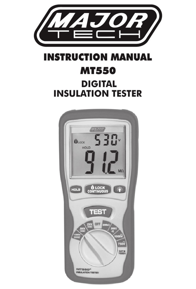
Major tech MT550 User manual

Major tech

Major tech MT550 User manual

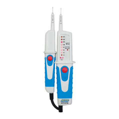
Major tech MT472 User manual

Major tech

Major tech MT472 User manual

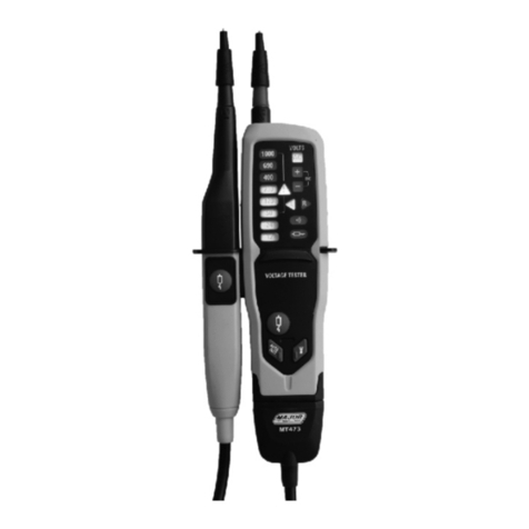
Major tech MT473 User manual

Major tech

Major tech MT473 User manual

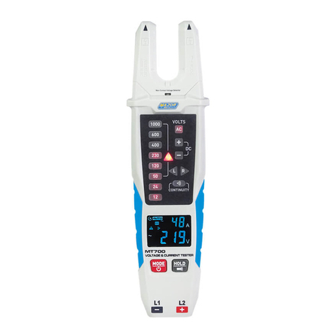
Major tech MT700 User manual

Major tech

Major tech MT700 User manual

Major tech MT585 User manual

Major tech

Major tech MT585 User manual

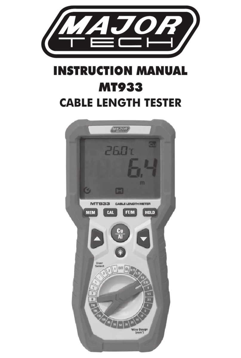
Major tech MT933 User manual

Major tech

Major tech MT933 User manual

Major tech MT575 User manual

Major tech

Major tech MT575 User manual

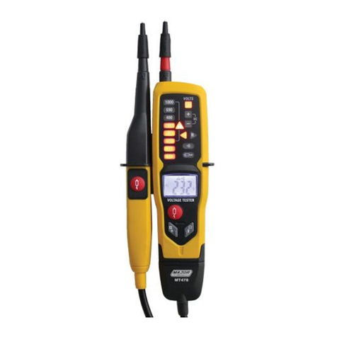
Major tech MT478 User manual

Major tech

Major tech MT478 User manual

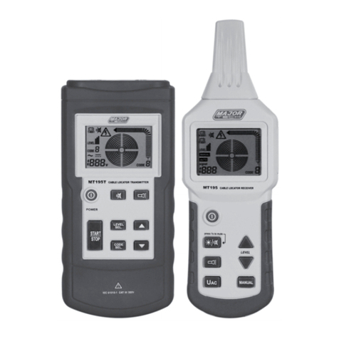
Major tech MT195 User manual

Major tech

Major tech MT195 User manual

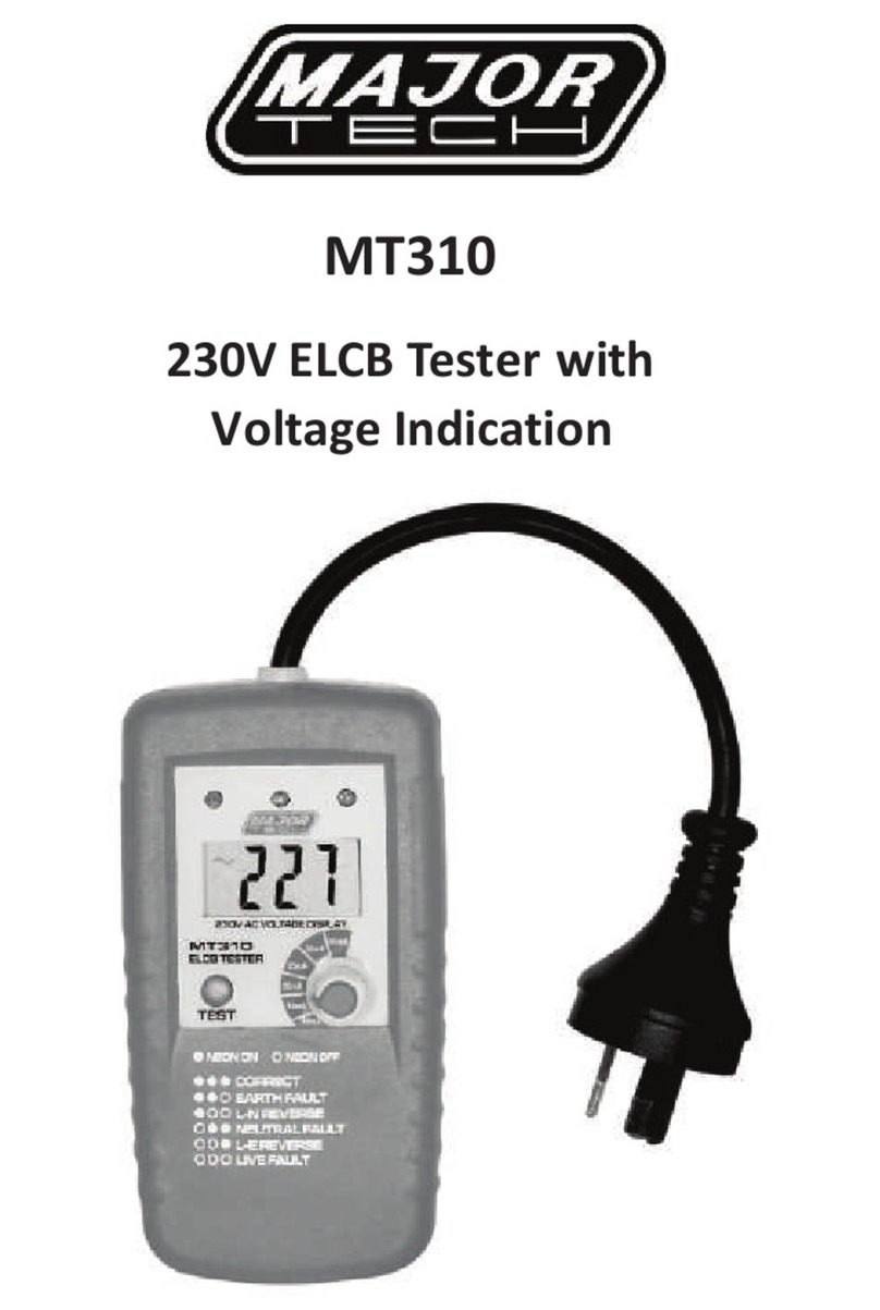
Major tech MT310 User manual

Major tech

Major tech MT310 User manual

Major tech MT123 User manual

Major tech

Major tech MT123 User manual

Major tech MT328 User manual

Major tech

Major tech MT328 User manual

Major tech MT390 User manual

Major tech

Major tech MT390 User manual

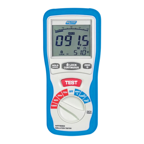
Major tech MT560 User manual

Major tech

Major tech MT560 User manual

Major tech MT474 User manual

Major tech

Major tech MT474 User manual

Major tech MT570 User manual

Major tech

Major tech MT570 User manual

Major tech MT235 User manual

Major tech

Major tech MT235 User manual

Major tech MT500 User manual

Major tech

Major tech MT500 User manual

Major tech MT325 User manual

Major tech

Major tech MT325 User manual

Major tech MT330 User manual

Major tech

Major tech MT330 User manual

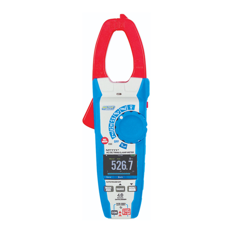
Major tech MT777 User manual

Major tech

Major tech MT777 User manual

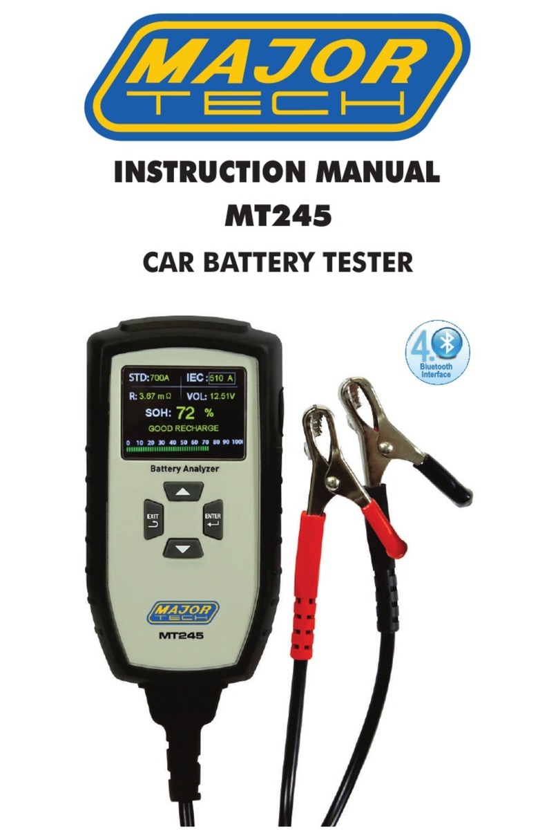
Major tech MT245 User manual

Major tech

Major tech MT245 User manual

Major tech MT390 User manual

Major tech

Major tech MT390 User manual

Popular Test Equipment manuals by other brands

HP 8340A operating manual

HP

HP 8340A operating manual

Viavi SmartClass Fiber OLTS-85 operating manual

Viavi

Viavi SmartClass Fiber OLTS-85 operating manual

KYORITSU 8031 instruction manual

KYORITSU

KYORITSU 8031 instruction manual

NI PXIe-5163 CALIBRATION PROCEDURE

NI

NI PXIe-5163 CALIBRATION PROCEDURE

METREL EasiTEST MI 2087 AL2 instruction manual

METREL

METREL EasiTEST MI 2087 AL2 instruction manual

Leclanche AlfaBat Pro Start

Leclanche

Leclanche AlfaBat Pro Start

Lollipop Femometer manual

Lollipop

Lollipop Femometer manual

Hanna Instruments HI 98103 instruction manual

Hanna Instruments

Hanna Instruments HI 98103 instruction manual

Humboldt HM-5760.3F product manual

Humboldt

Humboldt HM-5760.3F product manual

SKI AccuFlo Zero Installation and operating instructions

SKI

SKI AccuFlo Zero Installation and operating instructions

Milwaukee pH58 user manual

Milwaukee

Milwaukee pH58 user manual

JYE Tech DSO Shell 150 user manual

JYE Tech

JYE Tech DSO Shell 150 user manual

Anton Paar PMA 5 Instruction Manual and Safety Information

Anton Paar

Anton Paar PMA 5 Instruction Manual and Safety Information

Adeunis RF LoRaWAN Europe EU863-870 user guide

Adeunis RF

Adeunis RF LoRaWAN Europe EU863-870 user guide

UniPix ATMOS Quick reference guide

UniPix

UniPix ATMOS Quick reference guide

TRANSMATION MINITEMP 1061 manual

TRANSMATION

TRANSMATION MINITEMP 1061 manual

Valen RE856 Operation manual

Valen

Valen RE856 Operation manual

PCE Health and Fitness PCE-ATP 1 manual

PCE Health and Fitness

PCE Health and Fitness PCE-ATP 1 manual

manuals.online logo
manuals.online logoBrands
  • About & Mission
  • Contact us
  • Privacy Policy
  • Terms and Conditions

Copyright 2025 Manuals.Online. All Rights Reserved.