Space-Ray LoPro LPBL42-N5 User manual
Form No. 43539500
July 2021 A
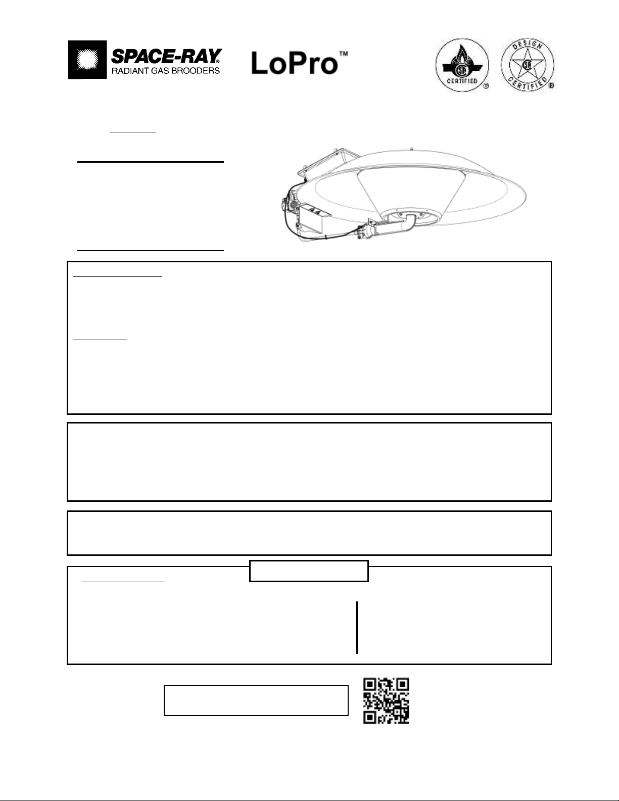
LOW PROFILE RADIANT GAS BROODER
MODELS: LPBL42-N5 / LPBL42-L5 with DIRECT SPARK IGNITION
INSTALLATION
AND OPERATION
INSTRUCTIONS
Patent Pending
OWNER/INSTALLER: For your safety this manual must be carefully read before installing, operating or
servicing this brooder. This brooder is intended for use with either Natural Gas or Propane Gas. It must be
installed by a qualified service person or a licensed contractor in accordance with state and local codes. In
the absence of these codes, the installation must conform to the National Fuel Gas Code ANSI Z223.1 (latest
edition) also know a NFPA54 or the CAN/CGA-B149.1/2 Installation Code in Canada.
WARNING: Improper installation, adjustment, alteration, service or maintenance can cause injury, property
damage or death. Refer to this manual. For assistance or additional information, consult a qualified
installer, service agency or the gas supplier.
INSPECT all combustion air openings into the building and, if necessary, clear as they become blocked by
litter, dust, feathers or other matter.
INSPECT and clean the brooder filters on a regular basis to allow proper brooder operation.
FOR YOUR SAFETY: EXHAUST FANS MUST be operating on an appropriate cycle when brooders are
operating to avoid a high concentration of carbon monoxide. When used without fresh air, this brooder may
give off carbon monoxide, an odorless and poisonous gas. CARBON MONOXIDE POISONING MAY LEAD TO
DEATH. Early signs of carbon monoxide poisoning resemble the flu with headaches, dizziness and nausea. If
you experience these signs, GET FRESH AIR IMMEDIATELY! Have the brooders serviced as soon as possible
and check the ventilation in the house.
These brooders are designed for agricultural applications and may operate with the use of either Natural Gas
or Liquid Propane (LP) Gas. Check the brooder’s nameplate to determine the correct gas type before
proceeding with installation.
IF YOU SMELL GAS:
!DO NOT try to light any appliance.
!DO NOT touch any electrical switch; do not use any
telephone in your building.
!IMMEDIATELY call your gas supplier from a neighbor's
telephone. Follow the gas supplier's instructions. If you
cannot reach your gas supplier, call the fire department.
DO NOT store or use gasoline or other
flammable vapors and liquids in the
vicinity of this or any other appliance.
SAVE THIS MANUAL
FOR FUTURE REFERENCE.
FOR YOUR SAFETY
Scan warranty QR code on the right to
register your product.

Form No. 43539500
July 2021 A –1–
TABLE OF CONTENTS
Section
Description Page
1.0)
GENERAL INFORMATION ............................................................................................ 1
2.0)
BROODER SPECIFICATIONS....................................................................................... 2
3.0)
BROODER CONTROL DESCRIPTION.......................................................................... 2
3.1)
BROODER ACCESSORIES .......................................................................................... 3
3.2)
PACKING LIST............................................................................................................... 5
4.0)
BROODER ASSEMBLY................................................................................................. 6
4.1)
GAS VALVE WIRE CONNECTIONS .............................................................................. 10
5.0)
MINIMUM CLEARANCES TO COMBUSTIBLES .......................................................... 12
6.0)
BROODER INSTALLATION........................................................................................... 12
7.0)
GAS CONNECTIONS ..................................................................................................... 13
7.1)
INSTRUCTIONS FOR TESTING OF GAS LEAKS AND PROPER GAS PRESSURE... 16
7.2)
GAS PIPE SIZING EXAMPLE ....................................................................................... 18
8.0)
ELECTRICAL CONNECTIONS ....................................................................................... 19
9.0)
LIGHTING AND SHUTDOWN INSTRUCTIONS............................................................ 22
10.0)
VENTILATION ................................................................................................................ 23
11.0)
CLEANING AND ANNUAL MAINTENANCE................................................................. 23
12.0)
TROUBLESHOOTING .................................................................................................... 26
13.0)
REPLACEMENT PARTS GUIDE.................................................................................... 28
1.0) GENERAL INFORMATION
This brooder is a self-contained infrared radiant brooder for agricultural locations where flammable gases or
vapors are not generally present.
Installation of the brooders must be in accordance with all applicable codes shown in the instructions and/or
the local codes and authorities having jurisdiction. In the absence of local codes, the brooder must be
installed in accordance to the National Fuel Gas Code ANSI Z223.1/NFPA54 in the U.S. or the CAN/CGA-
B149.1/2 Installation Code in Canada. Clearances to combustibles as outlined in the manual should always
be observed.
Inspect all openings and filters regularly and clean as necessary. This is necessary because litter, dust
feathers and other matter can become airborne and clog openings and filters and adversely affect brooder
operation and performance.
Every brooder should be located with respect to building construction and other equipment so as to permit
access to the brooders. Each installer shall use skillful and reliable installation practices when locating the
brooders and must give consideration to service accessibility.
This brooder is for INDOOR INSTALLATION ONLY and is used in an UNVENTED mode. The term Unvented
actually means Indirect Vented. While the products of combustion are expelled into the building, national
codes require ventilation in the building to dilute these products of combustion. This ventilation must be
provided by gravity or mechanical means. Ventilation requirements are addressed further in these
instructions.
This heater complies with IAS U.S. No. 8-94 (Draft No. 2) and CAN-1-2-20-M85.
Copies of the National Fuel Gas Code (ANSI Z223.1-latest edition) are available from the CSA at 8501 E.
Pleasant Valley Rd., Cleveland, OH 44131 or 55 Scarsdale Road, Don Mills, Ontario M3B 2R3. All NFPA
codes are available from the National Fire Protection Association, Batterymarch Park, Quincy, MA 02269.
This product can expose you to chemicals including ceramic fibers,
which are known to the State of California to cause cancer, and carbon
monoxide, which is known to the State of California to cause birth
defects or other reproductive harm. For more information go to
www.p65warnings.ca.gov.

Form No. 43539500
–2–July 2021 A
2.0) BROODER SPECIFICATIONS
INPUT RATING
Propane Gas:
42,000 BTU/h (12.31 kW)
Natural Gas:
42,000 BTU/h (12.31 kW)
Propane/Butane Mix Gas
42,000 BTU/h (12.31 kW)
GAS SUPPLY PRESSURE
Propane Gas:
11” – 14” W.C. (27.4 - 34.8 mbar)
Natural Gas:
5” – 14” W.C. (12.4 - 34.8 mbar)
Propane/Butane Mix Gas
11” – 14” W.C. (27.4 - 34.8 mbar)
MANIFOLD PRESSURE
Propane Gas:
10” W.C. (24.9 mbar)
Natural Gas:
4” W.C. (10.0 mbar)
Propane/Butane Mix Gas
10” W.C. (24.9 mbar)
ORIFICE SIZE
Propane Gas:
5/64” (.0781”)
Natural Gas:
3.1mm (.1220”)
Propane/Butane Mix Gas
1.8mm (.0709”)
MOUNTING HEIGHT
Recommended - 72” (1830mm)
BROODER SPACING
25’ – 40’ (7.6m – 12.2m)
BROODER SIZE
Canopy Diameter:
35” (890mm)
Brooder Height:
13.75” (349mm)
WEIGHT
Assembled Brooder:
21.5 lbs (10 kg)
VENTILATION REQUIRED
Per Brooder:
168 CFM (286 m3/hr)
GAS CONSUMPTION
Propane Gas:
0.46 GPH (1.75 L/hr)
Natural Gas:
0.42 Therm (44.3 MJ/hr)
Propane/Butane Mix Gas
0.46 GPH (1.75 L/hr)
ELECTRICAL SUPPLY
24 VAC, 1 Ph, 60Hz, 0.8A
3.0) BROODER CONTROL DESCRIPTION
Brooder Control No. 5 is designed for single or multi-zone installations using one or more thermostats. A
Zone Control (available as an accessory, Part No.43619050) is required to provide a 24-Volt power supply to
each brooder. The burner is controlled with a Direct Spark Ignition (DSI) switch, which is designed to provide
100 percent gas shut off of the main valve in the event that the main burner flame is not sensed.
Form No. 43539500
July 2021 A –3–
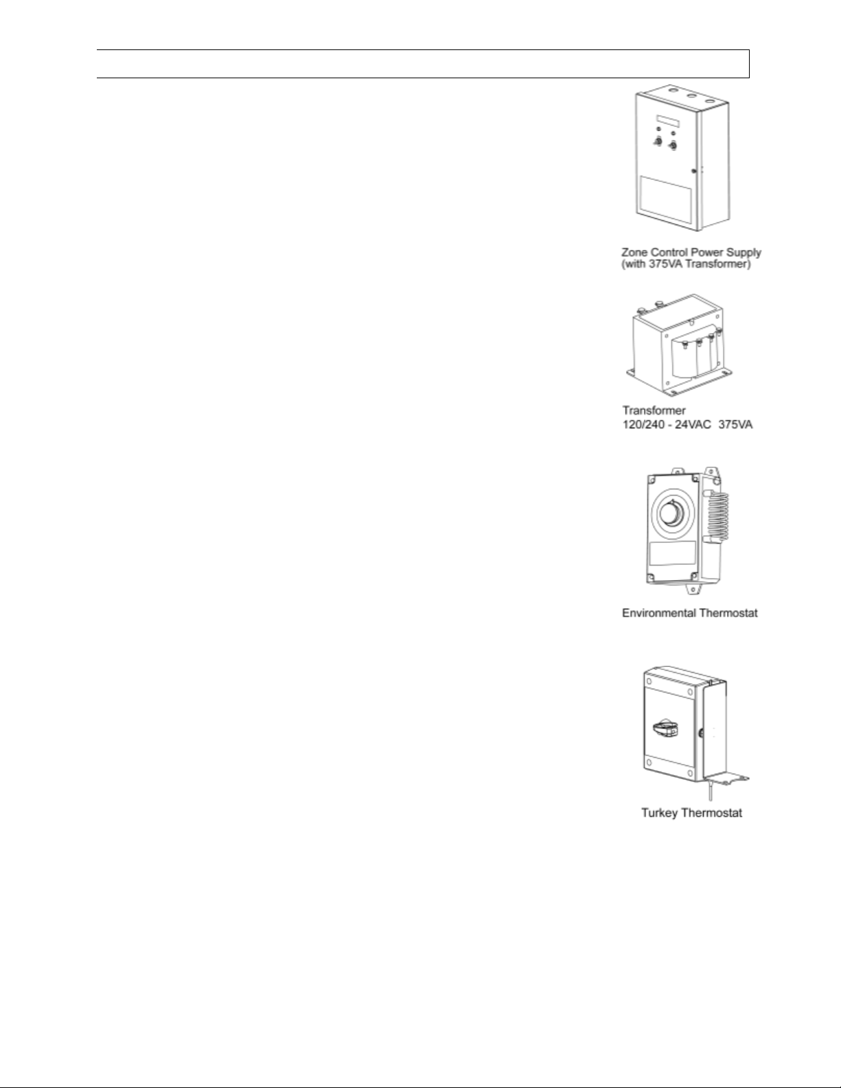
3.1) BROODER ACCESSORIES
A) Zone Control Panel Model ZCP22, Part No. 43619050
This is a power supply control which utilizes a 375VA transformer to
provide the required 24VAC for single or multiple groups (zones) of
brooders. Refer to electrical section of manual for allowable heater
quantities per transformer.
B) Transformer Replacement –375VA 120/240VAC
24VAC, Part No. 30222070
C) Thermostat –Environmental (EW-4-20), Part No. 30525010
Ratings: SPDT 120/240VAC, 16A Full Load
Temperature range: -40 Deg. F to 104 Deg. F +/- 2.5 Deg.F
Differential
Housing: Watertight ABS plastic meets NEMA 4x and NEC Article 547-
4 requirements for use in harsh environments. Adjustable dial allows
thermostat to be recalibrated.
D) Thermostat –Individual, Part No. 43317060
Temperature range: 58 Deg. F to 122 Deg. F with ten (10)
temperature scale ranges.
The thermostat is used to control individual brooders for Turkey heating
applications. Includes Mears thermostat, plastic enclosure, bracket and
screws to mount to White-Rodgers #25M18 gas valve.

Form No. 43539500
–4–July 2021 A
E) Transformer Kit, Part No. 44195160
This kit has a 120/24VAC 20VA transformer which
provides the required 24VAC for a single brooder. A
moisture proof junction box, cord connectors and wire nuts
are included.
F) Hose Kits - No. 5A Controls:
Part No. 30522060 - 6FT Hose with 3/8” swivel female flare fittings and 6” spring. Ball valve not included.
Part No. 30522100 - 10FT Hose with 3/8” swivel female flare fittings and 6” spring. Ball valve not included.
Part No. 30522069 - 6FT Hose with 3/8” swivel female flare fittings and 6” spring. Includes ball valve.
Part No. 30522109 - 10FT Hose with 3/8” swivel female flare fittings and 6” spring. Includes ball valve.
Kit Components:
Item Number
Part Number
Description
Qty
1
30241010
MALE FTG 45 FLARE 3/8 TUBE x 1/2 MPT (for gas shut-off valve)
1
2
30241000
MALE FTG 45 FLARE 3/8 TUBE x 3/8 MPT (for main gas valve)
1
3
30523060
HOSE, 3/8 ID x 6FT with 3/8" F SWIVEL FITTINGS and 6” Spring
1
4
30523100
HOSE, 3/8 ID x 10 FT with 3/8" F SWIVEL FITTINGS and 6” Spring
1
5
30285000
Manual Gas Shut-Off Ball Valve 1/2 FPT
1
G) Manual Gas Shut-Off Ball Valve –1/2”NPT, Part #30285000
H) Wire Brush –Long, Part #43295020
Wire Brush –Short, Part #43295010
This manual suits for next models
3
Table of contents
Popular Farm Equipment manuals by other brands

Schaffert
Schaffert Rebounder Mounting instructions

Stocks AG
Stocks AG Fan Jet Pro Plus 65 Original Operating Manual and parts list

Cumberland
Cumberland Integra Feed-Link Installation and operation manual

BROWN
BROWN BDHP-1250 Owner's/operator's manual

Molon
Molon BCS operating instructions

Vaderstad
Vaderstad Rapid Series instructions


