Spacerails Level 9 User manual

LEVEL 9
PRODUCT AND CONSUMER WARNING
CHOKING HAZARD: This product contains small parts and is not intended for children under 3.
• This product is intended for users 8 years of age and older.
• To avoid choking, keep small parts away from children.
• Use caution—this product contains parts with sharp edges.
• To avoid potential damage to the product, only insert the included marbles into the elevator.

Page 2 Seaich Corporation, LLC. All rights reserved. www.seaich.com |Spacerails, LLC. www.spacerails.com
PARTS INCLUDED
RECOMMENDED ITEMS (NOT INCLUDED)
Wire Cutters or Utility Scissors
Pen or Marker
6 AA Batteries (newer models) or 2 C Batteries
Ruler (in Centimeters)
ELEVATOR COMPONENTS
Power Box
x 2
Elevator Helix
x 38
Elevator Ring
x 9
Elevator Cover
x 4
Elevator Guard
x 11
Power Box Stand
x 2
Shaft Clip
x 1
Pendulum
x 1
Marble Catch
x 1
Counterweight
x 1
Pendulum Tray
x 1
Rail Splitter
x 3
STUNT COMPONENTS
SHAFT COMPONENTS
600mm
x 9
391mm
x 8
300mm
x 20
200mm
x 7
159mm
x 19
65mm
x 8
Shaft Cap
x 2
ARM COMPONENTS
Arm Clip
x 147
Arm Sheath
x 168
Arm Holder A
x108
Arm Holder B
x 265
Arm Lock
x 375
See-Saw Arm
x 2
Rail Coupling
x 15
Rail
76,000 mm
Rail Clip
x 300
Marble
x 12
RAIL COMPONENTS
BASE COMPONENTS
Base
x 13
Double Sided Base
x 1
Base Holder A
x 13
Base Holder B
x 10

Seaich Corporation, LLC. All rights reserved. www.seaich.com |Spacerails, LLC. www.spacerails.com Page 3
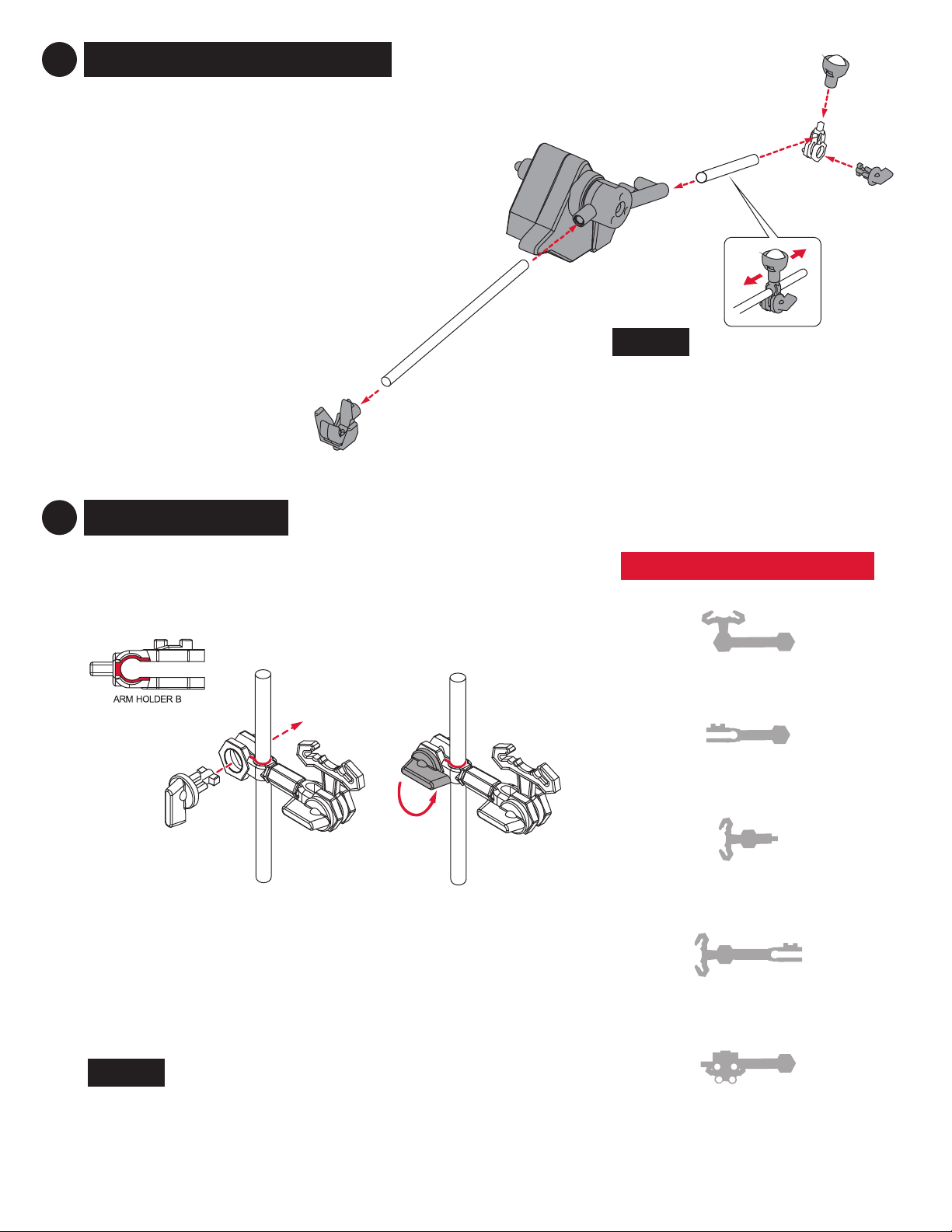
1PREPARE ARMS
Attach one Arm Holder B on each side
of the Arm Sheath.
Attach one Arm Holder B on each side
of the Arm Sheath. When assembling
shafts F, BC, and BD, slide one
ArmHolder B on shaft and insert one
ArmClip and add the Arm Lock.
BARM B QTY: 56
ARM D QTY: 3
AARM A QTY: 107
Slide Arm Holder B onto
shaft. Insert Arm Lock
through ArmHolder B and
Rail Clip. Turn the Arm Lock
counter-clockwise to secure
the Rail Clip in place. These will
be assembled during the shaft
assembly step to shafts D, E, F,
G, BC and BD.
ARM C QTY: 36
Step 1: Attach one Arm Holder A and one
Arm Holder B with one Arm Sheath. Insert
one Arm Clip into Arm Holder A.
Step 3: Turn the Arm Lock
counter-clockwise to secure
the Arm Clip in place.
Step 2: Insert Arm Lock through
Arm Holder A and Arm Clip.
To avoid damaging parts, do not move or adjust the Rail Clip while locked in the arm. To move the Rail Clip, release
Arm Lock by turning clockwise, position Rail Clip as desired, then secure Arm Lock again.
C
D
Cut two 7.5 cm lengths of rail and insert
into See-Saw as shown using a Rail Clip
to support the ends of the rail.
Attach Arm Holder B to the square receiver side of Arm Sheath
to create the arm. Attach the arm to the shaft and the shaft
to the base prior to attaching the round receiver side of the
ArmSheath to the See-Saw Arm.
SEE-SAW ARM QTY: 1 LEFT & 1 RIGHT

Page 4 Seaich Corporation, LLC. All rights reserved. www.seaich.com |Spacerails, LLC. www.spacerails.com
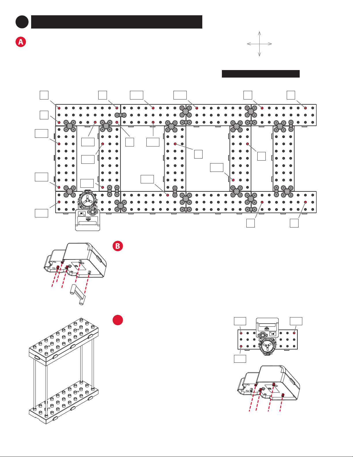
Step 1: Interlock all
Base block tabs as
shown above.
Step 2: Press Base Holder A and
Base Holder B pieces into the Base
blocks for a more secure hold.
NOTE:
Please see the included
full size drawings for the
next several steps. This will
simplify the positioning of
base, arms, shafts, and the
rail cut lengths.
Step 3: Assemble base blocks as shown in the
Illustration of completed base with all tabs
locked and Base Holders installed. Approximately
20% of actual size.
BASE ORIENTATION
BACK OF BASE
FRONT OF BASE
LEFT
OF BASE
RIGHT
OF BASE
2BASE ASSEMBLY
Seaich Corporation, LLC. All rights reserved. www.seaich.com |Spacerails, LLC. www.spacerails.com Page 5
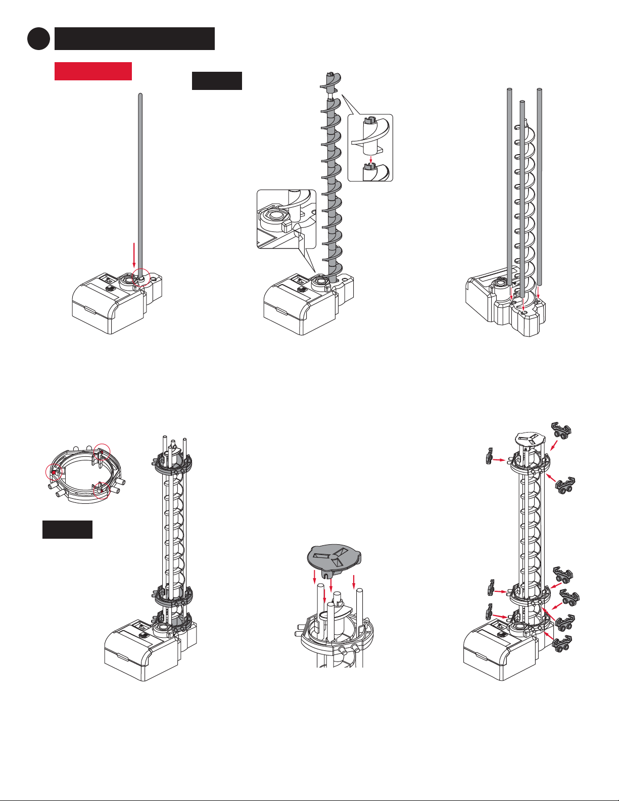
ELEVATOR A
Step 3: Once the corkscrew
is built, attach three 300 mm
support shafts to the Power Box.
Step 1: Place a 300 mm shaft in
the white hole on the Power Box.
Step 2: Connect Elevator Helix
pieces together with the male part
facing up to ll the shaft.
NOTE:
Install the rst Elevator
Helix piece male side
up and rotate it until
it slides in place and
engages with driver at
the base of Power Box.
Step 6: Attach Rail Clips to
each Elevator Ring as shown.
Step 4: Slide each Elevator Ring
into position on the support
shafts right-side up.
Step 5: Place the Elevator
Cover onto the top of the
elevator assembly.
NOTE:
Elevator Rings are
right side up when
tabs in red are on
the top.
240 mm
40 mm
0 mm
3ELEVATOR ASSEMBLY
Page 6 Seaich Corporation, LLC. All rights reserved. www.seaich.com |Spacerails, LLC. www.spacerails.com
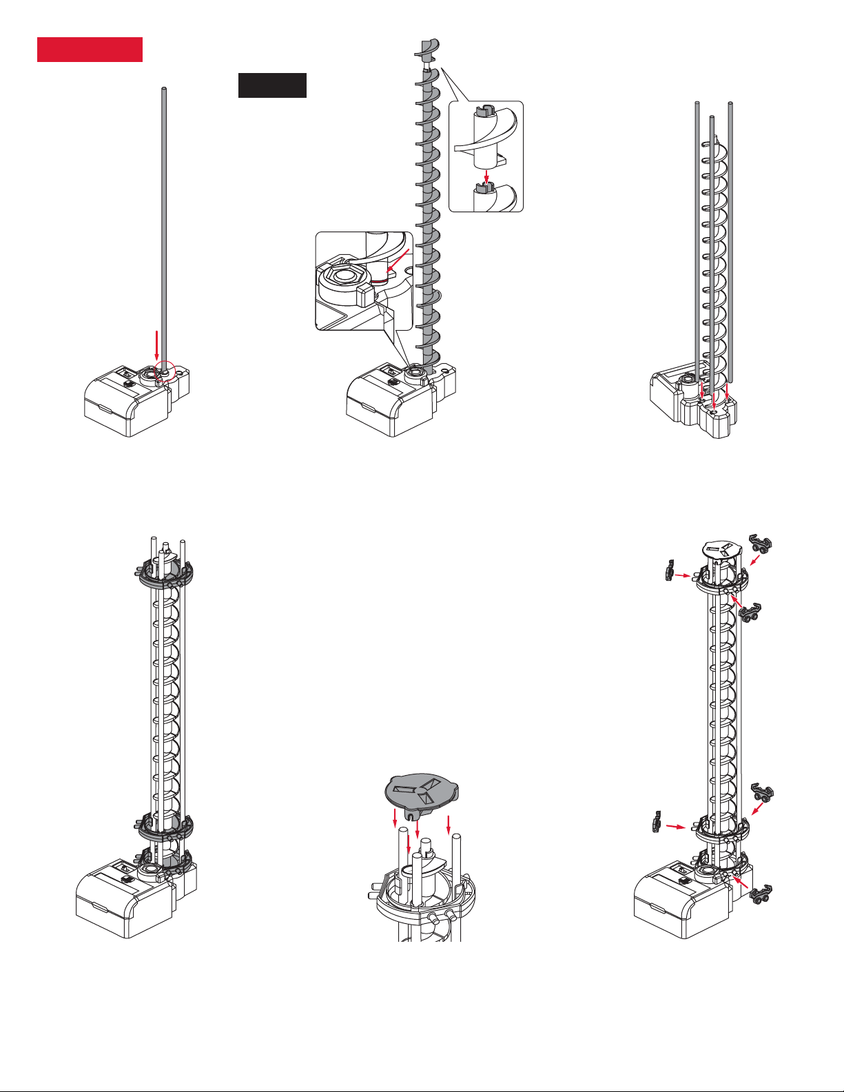
ELEVATOR B
Step 3: Once the corkscrew
is built, attach three 391 mm
support shafts to the Power Box.
Step 1: Place a 391 mm shaft in
the white hole on the Power Box.
Step 2: Connect Elevator Helix
pieces together with the male part
facing up to ll the shaft.
NOTE:
Install the rst Elevator
Helix piece male side
up and rotate it until
it slides in place and
engages with driver at
the base of Power Box.
Step 6: Attach Rail Clips to
each Elevator Ring as shown.
Step 5: Place the Elevator Cover
onto the top of the elevator
assembly.
Step 4: Slide each Elevator Ring
into position on the support
shafts right-side up.
335 mm
30 mm
0 mm

Seaich Corporation, LLC. All rights reserved. www.seaich.com |Spacerails, LLC. www.spacerails.com Page 7
ELEVATOR C
Step 3: Once the
corkscrew is built,
attach three 300 mm
support shafts to the
Elevator Cover.
Step 1: Insert a 300 mm
shaft rst into a Shaft Cap
and then into the center
hole of an Elevator Cover.
Add the Shaft Clip 2 cm up
from the base.
Step 2: Connect
Elevator Helix pieces
together with the
male part facing up
to ll the shaft.
Step 6: Attach Rail
Clips to each Elevator
Ring as shown.
Step 5: Place the Elevator
Cover onto the top of the
elevator assembly.
2 cm
Step 4: Slide each
Elevator Ring into
position on the
support shafts
right-side up.
NOTE:
The Marble may
fall out of the
elevator if it
enters too fast.
Add Elevator Guards to the right of each
Rail Clip installed to the bottom two
Elevator Rings.
ADDING GUARDS: Repeat this step for all
three elevators that have been built.
75 mm
185 mm
0 mm
Page 8 Seaich Corporation, LLC. All rights reserved. www.seaich.com |Spacerails, LLC. www.spacerails.com
4PREPARE PENDULUM STUNT
Attach the Marble Catch to a 200 mm shaft. Insert
other end of shaft to the left side of the Pendulum.
Next attach an Arm Holder B to a 65 mm shaft with
an Arm Lock and add the Counterweight to the post
of Arm Holder B. Finally, attach the 65 mm shaft to
the right hand side of the Pendulum.
NOTE:
The Counterweight is adjustable, if the
pendulum stunt is not working, try
moving the weight to dierent positions.
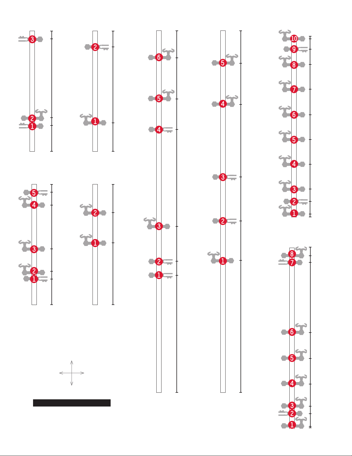
NOTE:
The shafts listed below contain no arms and are not included in the drawings.
Shafts: I, J, L, M, N, O, W, X, Y, Z, AX, AY, and AZ
Step 1: Slide Arm Holder B of each arm on to a shaft and lock in
place with Arm Lock. Refer to the next pages for orientation and
location of each arm.
Step 2: Attach each arm as shown in step 1 with the orientation
and location shown on the following pages. In later steps the letter
of each shaft and number of each arm will guide in the installation
of the rails. For example Arm A-3 is 104 mm from the base.
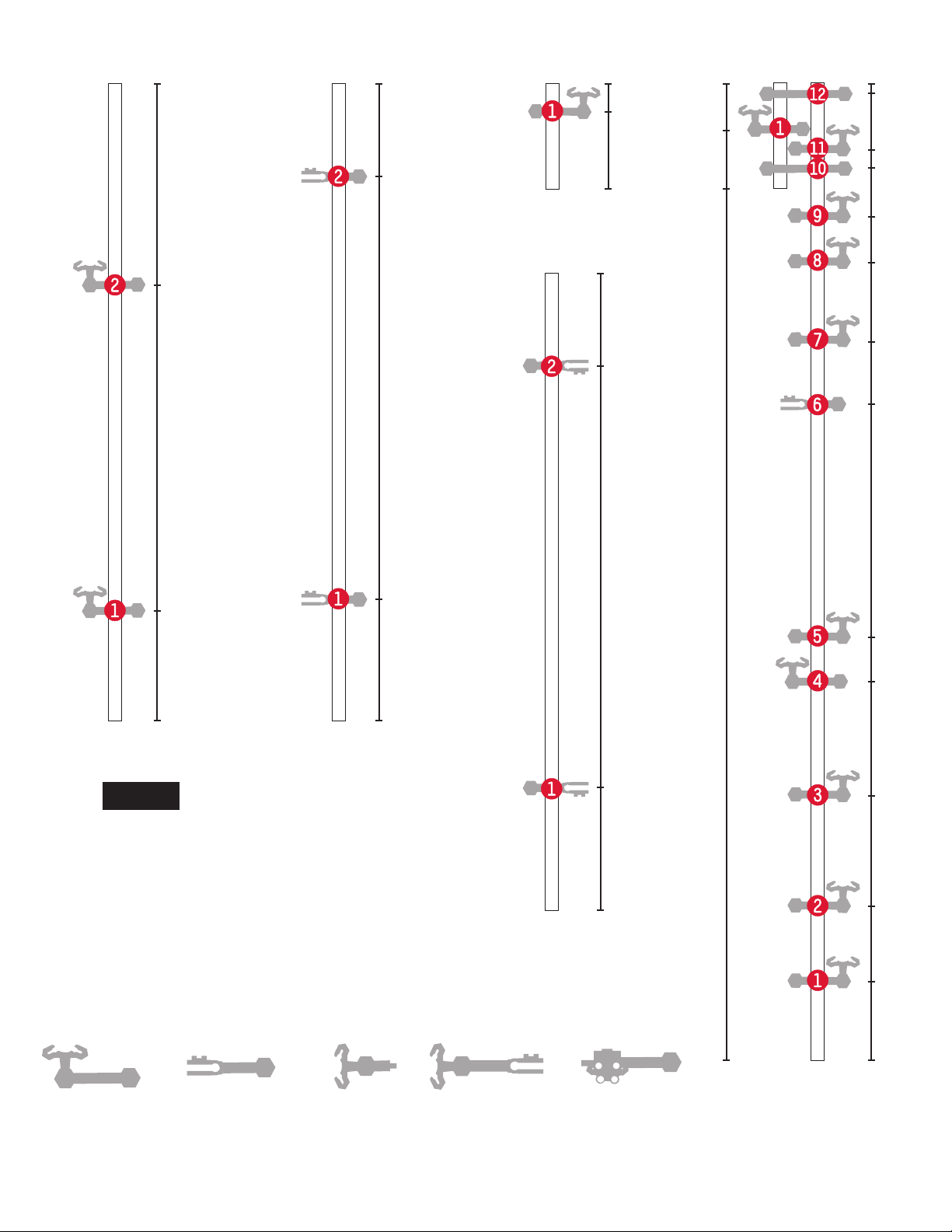
Shaft illustrations are approximately 37% of actual size. All shaft
measurements are in Millimeters.
Arm A
Arm B
Arm C
Arm D
See-Saw Arm
ARM TYPE REFERENCE
5SHAFT ASSEMBLY

Seaich Corporation, LLC. All rights reserved. www.seaich.com |Spacerails, LLC. www.spacerails.com Page 9
Shaft A Shaft C Shaft D Shaft F
10
600
44
54
104
168
185
242
267
315
335
448
500
563
578
310
355
Shaft B
600
44
54
185
340
524
595
300
46
100
129
158
187
216
245
286
Shaft E
300
46
112
141
170
198
228
257
286
300
100
40
130
160
190
224
291
10
Shaft G
300
105
135
165
195
225
291
285
TOP
BASE
FRONT
OF BASE
BACK
OF BASE
SHAFT TO BASE ORIENTATION
Page 10 Seaich Corporation, LLC. All rights reserved. www.seaich.com |Spacerails, LLC. www.spacerails.com
Shaft H
44
54
186
200
Shaft K
44
55
95
186
168
200
Shaft P
50
173
200
Shaft Q
105
155
200
TOP
BASE
FRONT
OF BASE
BACK
OF BASE
SHAFT TO BASE ORIENTATION
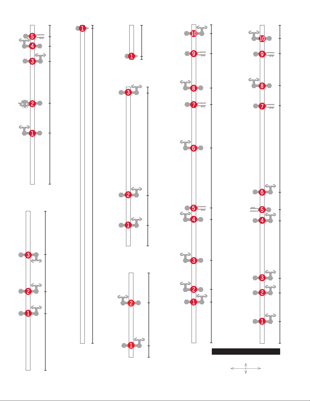
Shaft R Shaft S
600 600
194
217 222
278 284
357
436
480
490
558 550
Shaft T
Shaft U
300
3
3
17
18
36
46
78
88
119
131
163
172
214
279
290
300
278
255
295
Seaich Corporation, LLC. All rights reserved. www.seaich.com |Spacerails, LLC. www.spacerails.com Page 11
Arm A Arm B Arm C Arm D See-Saw Arm
Shaft V
70
270
391
Shaft AB
75
335
391 600
51
98
166
235
262
402
445
493
520
550
562
593
535
576
600
Shaft AE & AF
75
335
391
Shaft AD
65
49
Shaft AC
NOTE:
If you want to jump ahead you can start
adding the arms to the base at any time. Keep
in mind that some arms like H and K utilize
the Arm B connectors to attach to other
shafts and are suspended above the base.
Page 12 Seaich Corporation, LLC. All rights reserved. www.seaich.com |Spacerails, LLC. www.spacerails.com
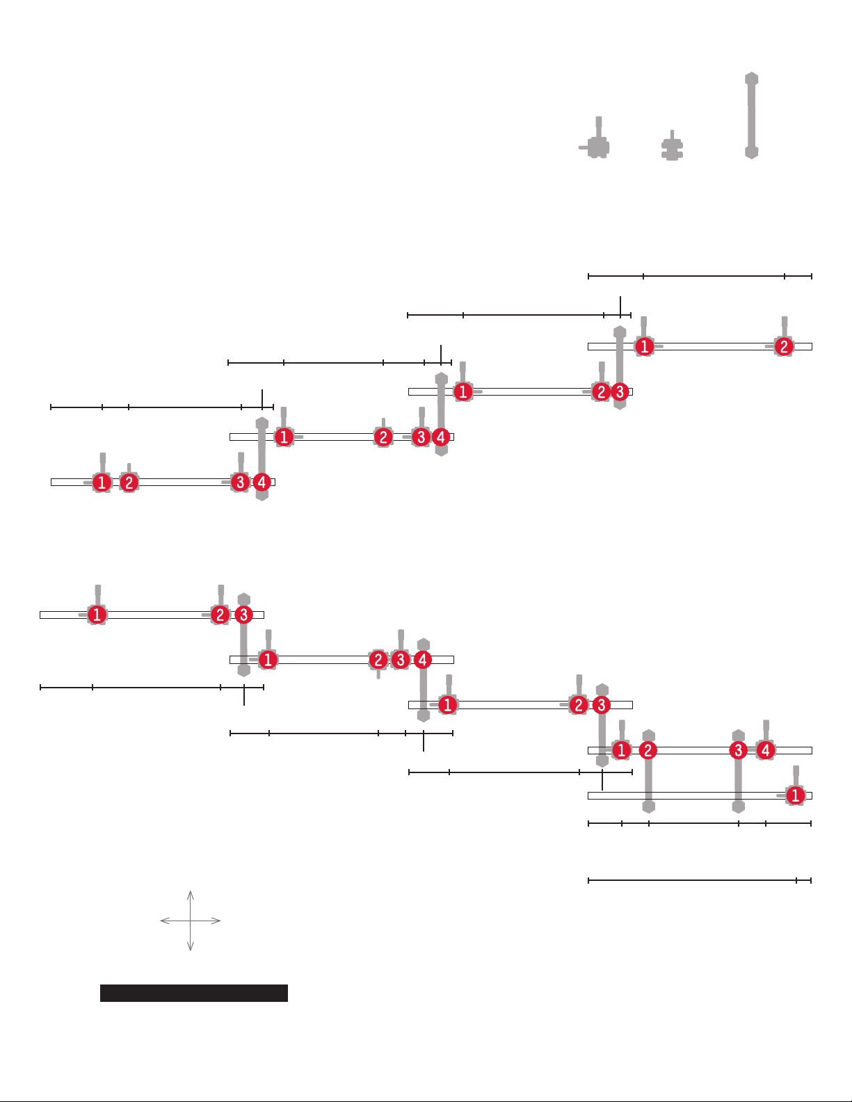
STAIR STUNT ARMS
The arms for this stunt are connected to each other and will build a
suspended stair stunt. For now just build the arms as shown here.
Some of the arms on this page are shown from the narrowest side.
For example: the arm AG-1 is seen from the end with the Rail Clip
above the arm. The Arm Lock is also visible on the side. Arm AG-4 is
an Arm B and is shown connecting shafts AG and AH together. Arm BArm A Arm B
Shaft AG
Shaft AK
Shaft AL
Shaft AO
Shaft AM
Stair Stunt A
Stair Stunt B
Shaft AH
Shaft AI
Shaft AJ
SHAFT ORIENTATION STAIRS
UP
DOWN
LEFT SIDE
OF BASE
RIGHT SIDE
OF BASE
40
40
40 110
140
140
140
150
150
40
40
20
20
20
50 140
130
110 120
120
40 100 120
145
150
150
140
140
Shaft AN
Seaich Corporation, LLC. All rights reserved. www.seaich.com |Spacerails, LLC. www.spacerails.com Page 13
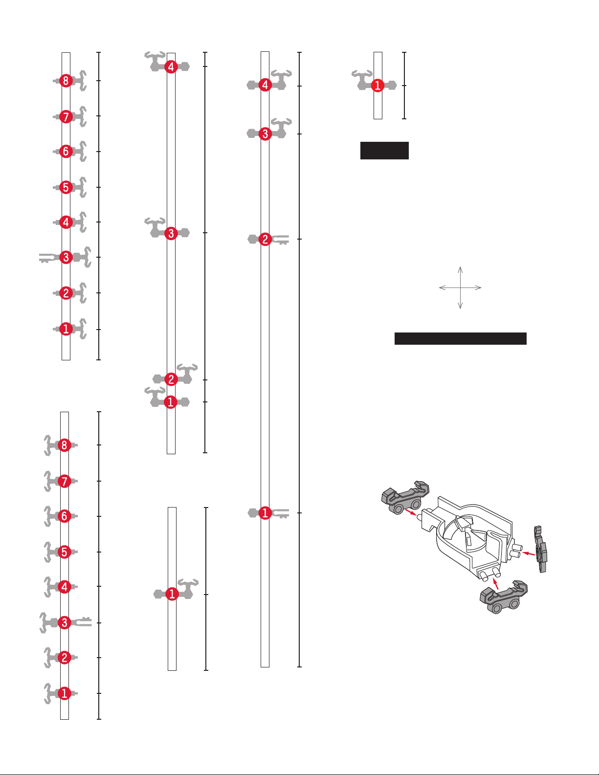
Shaft AP
Shaft AQ
300
99
152
235
279
263
110
151
215
300
Shaft AR Shaft AV Shaft AW
600
594
Shaft AT
Shaft AU
99
42
300
292
600
80
103
158
235
254
370
449
483
545
586
600
44
98
126
236
250
288
447
488
545
577
105
25
159
Shaft AS
65
4
TOP
BASE
FRONT
OF BASE
BACK
OF BASE
SHAFT TO BASE ORIENTATION
Page 14 Seaich Corporation, LLC. All rights reserved. www.seaich.com |Spacerails, LLC. www.spacerails.com
Shaft BC
300
30
65
100
135
168
203
237
272
Shaft BD
25
60
94
129
163
198
232
267
300 57
67
218
391
Shaft BE
380
Shaft BF
77
159
Shaft BG
600
150
417
523
570
Shaft BH
65
35
NOTE:
Please see the included full size drawings.
This will simplify the positioning of base,
arms, shafts, and the rail cut lengths.
TOP
BASE
FRONT
OF BASE
BACK
OF BASE
SHAFT TO BASE ORIENTATION
RAIL SPLITTERS
Step 1: Attach one Rail Clip on each
of the Rail Splitter posts.
Seaich Corporation, LLC. All rights reserved. www.seaich.com |Spacerails, LLC. www.spacerails.com Page 15
ATTACH ELEVATOR TO BASE
Step 1: Attach Power Box Stand
to the Power Box.
Step 2: Firmly seat the posts
from the Power Box in the holes
on the base.
ADDING THE UPPER FLOOR
Step 1: Add the Double Sided Base
over the back left base block using
shafts N, O, P, and Q.
Step 2: Add the shafts in the
diagram to the upper oor.
Step 3: Firmly seat the posts from
the Power Box in the holes on the
Upper Base. Do not attach a Power
Box Stand. This elevator is pushed
forward and attaches with
dierent posts.
Attach posts
to base
Use diagram below for location of each shaft. Push
shaft into holes on base until sturdy. Refer to drawings
on pages 9-14 for orientation of shaft to the base.
SHAFT ORIENTATION STAIRS
BACK OF BASE
FRONT OF BASE
LEFT SIDE
OF BASE
RIGHT SIDE
OF BASE
AC
AV
BH AW
BG
AQ
AP AE
AU
BF
AT
N
O
P
Q
S
K A
HC
V
AB
AD
BE
Attach posts to
the upper base
6ADDING SHAFTS AND ELEVATORS TO BASE
C
Page 16 Seaich Corporation, LLC. All rights reserved. www.seaich.com |Spacerails, LLC. www.spacerails.com
ROUND ABOUT STUNT SUSPENDED SHAFTS
Step 1: Attach shafts W and X (159 mm) to the arms on shaft
AB so that they extend to the left of the base. Add Arm Locks
as needed.
Step 2: Attach shafts Y and Z (159 mm) to the arms on shaft
AD so that they extend to the left of the base.
Step 3: Attach shaft T to shaft W and X. The arms of shaft T
should face the back of the base.
Step 4: Attach shaft U to shaft Y and Z. The arms of shaft U
should face the front of the base.
Illustration shows how
to suspend an arm using
arm type B.
AB AD
W
T
U
Y
X
Z
N O
Completed view from left of base.Completed view from front of base.
AD
U
Y
Z
O
NOTE:
Remember to insert Arm Locks for all arms as they are
connected. This will help keep things from shifting
around unintentionally. If you need to move an arm
do not force it. Release the Arm Lock reposition arm
and return Arm Lock to the locked position.
Seaich Corporation, LLC. All rights reserved. www.seaich.com |Spacerails, LLC. www.spacerails.com Page 17
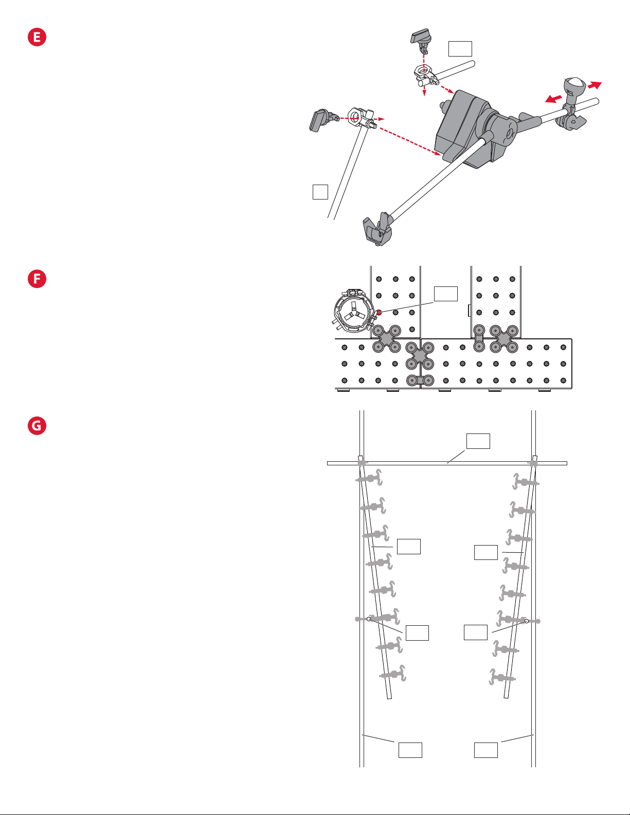
ADDING PENDULUM TO STRUCTURE
Step 1: Attach shaft R at about a 45° angle
above the base with the bottom of the shaft
connecting at arm P-2, AP-5, and AE-6. The
shaft should sit just in front of the back row of
shafts and angle up and to the right.
Step 2: Attach shaft AS at arm A-13. Shaft AS
should angle down and to the left side
of the base.
Step 3: With the pendulum facing the front of
the base insert the post of arm AR-1 into the
hole on the back left side of the pendulum.
Step 4: Finish by inserting arm AS-1 into the
hole on the back of the pendulum on
the right side.
ADDING ELEVATOR C
Attach elevator C on the left side to arm BG-1
and arm BG-2. The bottom of elevator C should
be approximately 125 cm above the base and
the center shaft of elevator C should line up
with arm BG when observed from the right side
of the base. Fine tuning will be required
as rails are attached to keep everything
running smoothly.
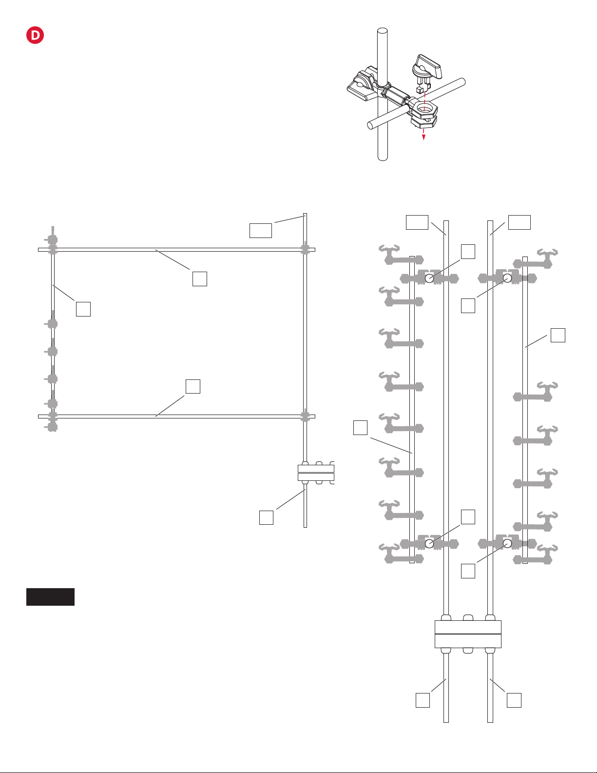
VERTICAL FUNNEL SUSPENDED SHAFTS
Step 1: Connect shaft AZ (300 mm) at arms
AV-9 and AW-9. This will give added support
to the stunt and keep the top of these shafts
evenly spaced.
Step 2: Next attach shaft AX at arm AV-5
parallel to the base. Then attach shaft AY at arm
AW-5 parallel to the base.
Step 3: Now the funnel shape will be created
starting at the bottom by attaching shaft BC
from arm BC-3 to shaft AX and shaft BD from
arm BD-3 to shaft AY.
Step 4: For the top of the funnel shape connect
shaft BC to arm AV-7 and shaft BD at arm AW-7.
Target a distance of 15 cm at the bottom of the
funnel and 23.5 cm at the top with the bottom
approximately 14.5 cm from the base.
AS
R
BG
AV
AZ
BC
AX AY
BD
AW

Page 18 Seaich Corporation, LLC. All rights reserved. www.seaich.com |Spacerails, LLC. www.spacerails.com
DOUBLE LOOP STUNT SUSPENDED SHAFTS
Step 1: Attach shaft I to the arms H-3 and C-3. Attach shaft
J to the arms H-1 and C-1. This creates a box shape when
observing from the front of the base.
Step 2: Attach shaft L to the arms A-5 and K-5. Attach shaft
M to the arms A-1 and K-1. This creates a box shape when
observing from the back of the base.
Step 3: Attach shaft E centered between shafts L and I using
arms E-1 and E-8. The arms of shaft E should face down.
Step 4: Attach shaft D centered between shafts J and M using
arms D-1 and D-8. The arms of shaft D should face up.
Step 5: Attach shaft F between shafts H and K 100 cm above
the base using arms F-1 and F-8. The arms of shaft F should
face to the right. Attach F-2 to shaft V for additional support.
Step 6: Attach shaft G between shafts A and C 100 cm above
the base using arms G-1 and G-8. The arms of shaft G should
face to the left.
Step 7: Attach shaft R to arm G-3 and rest on working surface.
Shaft R is not over the base.
STAIR STUNT SUSPENDED ARMS
Step 1: Take stair stunt part A and slide into position so that it can connect
to arms S-3, V-3 and R-4. This is the upper portion of the stair stunt.
Step 2: Take stair stunt part B and move into position so that it can connect
to arms S-1, V-3, R-2 and R-1. This is the lower portion of the stair stunt.
S
V
R
Stair Stunt A
Stair Stunt B

Seaich Corporation, LLC. All rights reserved. www.seaich.com |Spacerails, LLC. www.spacerails.com Page 19
C
7 cm (qty: 3)
D
7.5 cm (qty: 4)
E
16 cm (qty: 2)
F
21 cm (qty: 4)
G
34 cm (qty: 6)
H
43.5 cm (qty: 1)
I
46 cm (qty: 2)
J
54 cm (qty: 2)
K
55 cm (qty: 2)
L
66 cm (qty: 2)
M
71 cm (qty: 2)
N
75 cm (qty: 2)
O
86 cm (qty: 2)
P
90 cm (qty: 2)
Q
93 cm (qty: 2)
R
100 cm (qty: 2)
S
175 cm (qty: 2)
T
188 cm (qty: 2)
U
194 cm (qty: 2)
V
475 cm: (qty 2)
W
550 cm (qty: 2)
X
560 cm (qty: 2)
Y
670 cm
(qty: 2)
A
5 cm (qty: 1)
B
5.5 cm (qty: 2)
7CUT THE RAIL
Step 1: Measure each section and mark the cutting point with a pen.
Step 2: Cut each section according to your measurement. Make sure
to cut at a 90° angle.
Tip: To help avoid do-overs and using too much rail, cut generously (slightly
longer than required) to begin with. You can always cut a long rail shorter.
NOTE:
Illustration of rail lengths is 2.6% of actual size.
Please see the included full size drawings. This will
simplify the positioning of base, arms, shafts, and
the rail cut lengths.

Page 20 Seaich Corporation, LLC. All rights reserved. www.seaich.com |Spacerails, LLC. www.spacerails.com
Connecting rails to arms: To install the rails, press them into the arm as
shown. You should hear a click when the rail is locked in place.
When building a curve, Rail Clips and Arm Clips
can be adjusted to create a banked curve. Plenty
of Rail Clips are included so that they can be
applied liberally.
Attach Rail Clips every 8-10 cm along rail to
maintain stability and keep rails parallel. Keeping
rails uniform maintains speed and avoids throwing
the Marble o course.
Rails should extend into the elevator
enough to catch the Marble.
Rail Couplings are provided but not needed.
If more length is needed for a rail, insert the
coupling into the end of both rails being joined.
Keep incline as smooth as possible to avoid
losing speed or contact with rails.
8INSTALLING RAILS
Add the Catch Tray to the pendulum drop
stunt to make it easier to catch the marbles.
Table of contents
Other Spacerails Toy manuals

Spacerails
Spacerails LEVEL 4 User manual

Spacerails
Spacerails Level 5 User manual

Spacerails
Spacerails Level 3 User manual

Spacerails
Spacerails Level 2 User manual

Spacerails
Spacerails Level 1 User manual

Spacerails
Spacerails LEVEL 6 User manual

Spacerails
Spacerails Level 8 User manual

Spacerails
Spacerails Level 7 User manual


