Spacerails Level 5 User manual

LEVEL 5
PRODUCT AND CONSUMER WARNING
CHOKING HAZARD: This product contains small parts and is not intended for children under 3.
• This product is intended for users 8 years of age and older.
• To avoid choking, keep small parts away from children.
• Use caution – this product contains parts with sharp edges.
• To avoid potential damage to the product, only insert the included marbles into the elevator.

Page 2 Seaich Corporation, LLC. All rights reserved. www.seaich.com |Spacerails, LLC. www.spacerails.com
FRONT
BACK
LEFT RIGHT

Seaich Corporation, LLC. All rights reserved. www.seaich.com |Spacerails, LLC. www.spacerails.com Page 3
Keep parts together to avoid misplacing them.
ELEVATOR COMPONENTS
Arm Clip
x80
Arm Sheath
x80
Arm Holder A
x80
Arm Holder B
x85
Arm Lock
x165
Base
x12
Base Holder A
x6
Base Holder B
x4
PARTS INCLUDED
ARM COMPONENTSBASE COMPONENTS
Power Box
x1
Shaft (391mm)
x11
Elevator Helix
x16
Elevator Ring
x3
Elevator Cover
x1
Elevator Guard
x5
Power Box Stand
x1
Shaft (300mm)
x10
Shaft (200mm)
x2
Shaft Connector
(176mm) x1
Shaft Connector
(154mm) x3
Shaft Connector
(90mm) x2
SHAFT COMPONENTS SPLITTER COMPONENTS
ROTATION BLOCK COMPONENTS
Shaft (159mm)
x1
Shaft (65mm)
x1
Pendulum
x1
Marble Catch
x1
Counterweight
x1
START BLOCK COMPONENTS
Start Block
x1
Start Block
Cover x1
Wire Cutters or Utility Scissors
Pen or Marker
3 AA Batteries (newer models) or 1 C Battery
Ruler (in Centimeters)
REQUIRED TOOLS AND ITEMS NOT INCLUDED
Rail Splitter
x2
See-Saw Arm
x2
RAIL COMPONENTS
Pendulum Tray
x1
Steel Marble
x5
Rail Clip
x90
Rail Coupling
x10 Rail
Rail
34,000mm
Page 4 Seaich Corporation, LLC. All rights reserved. www.seaich.com |Spacerails, LLC. www.spacerails.com
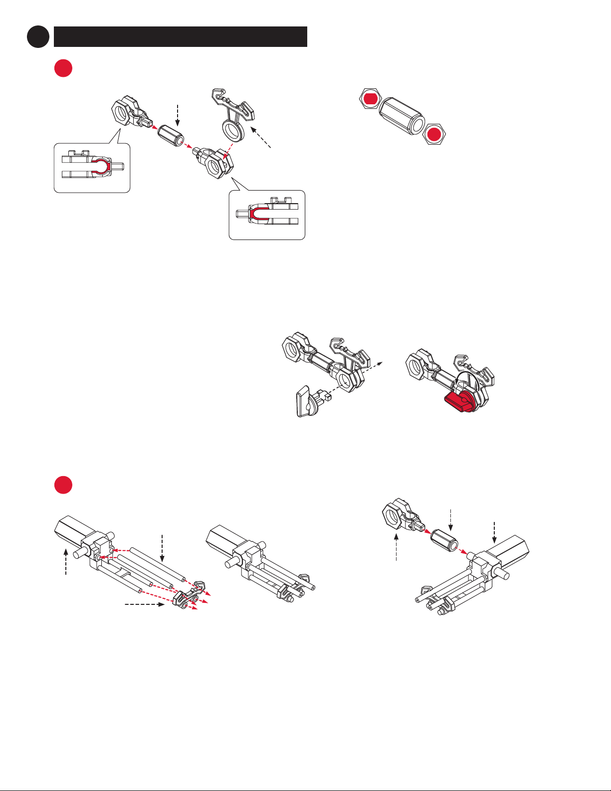
Step 1: Attach one Arm Holder A and one
ArmHolderB into one Arm Sheath. Insert one
Arm Clip into Arm Holder A.
Step 2: Insert Arm Lock through ArmHolderA
and Rail Clip. Carefully turn the Arm Lock
counter-clockwise to secure it in place.
PREPARE THE COASTER COMPONENTS
A
1
ARM ASSEMBLY QTY: 80
Arm Holder B
Arm Holder A
Arm Clip
Arm Sheath
Step 1: Cut two rails, each 55mm in length. Insert them
into the See-Saw Arm and the Rail Clip as shown above.
Step 2: Repeat for second See-Saw assembly.
BSEESAW ASSEMBLY QTY: 2
See-Saw
55mm Rails (2)
Rail Clip
Completed
See-Saw
assembly
Arm Holder B
Step 3: Attach one Arm Holder B into one Arm Sheath.
Insert the completed See-Saw assembly into the
ArmSheath.
Step 4: Repeat for second See-Saw assembly, installing
the Arm Holder B on the opposite side.
Note: The Arm Sheath
has two dierent holes:
Arm Holder B goes in
the squarish hole; all
other devices go in the
round hole.
Completed
See-Saw
assembly
Arm Sheath

Seaich Corporation, LLC. All rights reserved. www.seaich.com |Spacerails, LLC. www.spacerails.com Page 5
CBASE ASSEMBLY
To avoid damaging parts, do not move or adjust parts while Arm Locks are engaged. To move the parts, release the
Arm Lock by turning clockwise, position the part as desired, then secure the Arm Lock again.
Step 1: Interlock Base block tabs as shown below.
Base Holder A
Base Holder B
Step 2: Press Base Holder A and Base Holder B pieces
into the Base blocks for a more secure hold.
Base Holder A
Base Holder B
Page 6 Seaich Corporation, LLC. All rights reserved. www.seaich.com |Spacerails, LLC. www.spacerails.com
Step 3: Once the corkscrew is built,
attach three 391mm support shafts
to the Power Box.
DELEVATOR ASSEMBLY
Step 2: Connect 15 more Elevator
Helix pieces together with the male
part facing up to ll the shaft.
NOTE:
Install the rst Elevator
Helix piece male side
up and rotate it until
it slides in place and
engages with driver at
the base of Power Box.
Step 1: Place a 391mm Shaft
in the white hole on the
Power Box.
Step 4: Place the Elevator
Cover onto the top of the
elevator assembly.
Step 6: Place the
three Elevator Rings
over the three shafts.
Step 5: Connect Rail Clips to
each Elevator Ring as shown.
(Note that the middle ring
only gets two Rail Clips.)
Install Elevator Rings with tabs
facing up, as shown above.
Entry 1
Entry 2
Entry 3
Entry 4
Entry 5
Exit 1 Exit 2
Exit 3

Seaich Corporation, LLC. All rights reserved. www.seaich.com |Spacerails, LLC. www.spacerails.com Page 7
ROTATION ASSEMBLY
F
300mm Shaft
Arm Holder B
Arm
Lock
Arm Lock
Arm Holder B
Counterweight
Arm Lock
Rotation Gear
Marble Catcher
159mm Shaft
65mm Shaft
Step 1: Assemble
parts as illustrated.
Counterweight: If the rotation
is not functioning properly,
adjust the position of the
Counterweight until it does so.
ERAIL SPLITTER
Prepare Rail Splitter:
Attach one Rail Clip to each
of the Rail Splitter posts.
Step 8: Attach Power Box to
the Power Box Stand.
Insert into
holes on base
Power Box
Power Box Stand
Step 7: Attach
an Elevator
Guard to each
of the Elevator
Rings, then to
the right side of
the Rail Clip.
NOTE:
The Marble may fall out of the
elevator if it enters too fast.
Page 8 Seaich Corporation, LLC. All rights reserved. www.seaich.com |Spacerails, LLC. www.spacerails.com
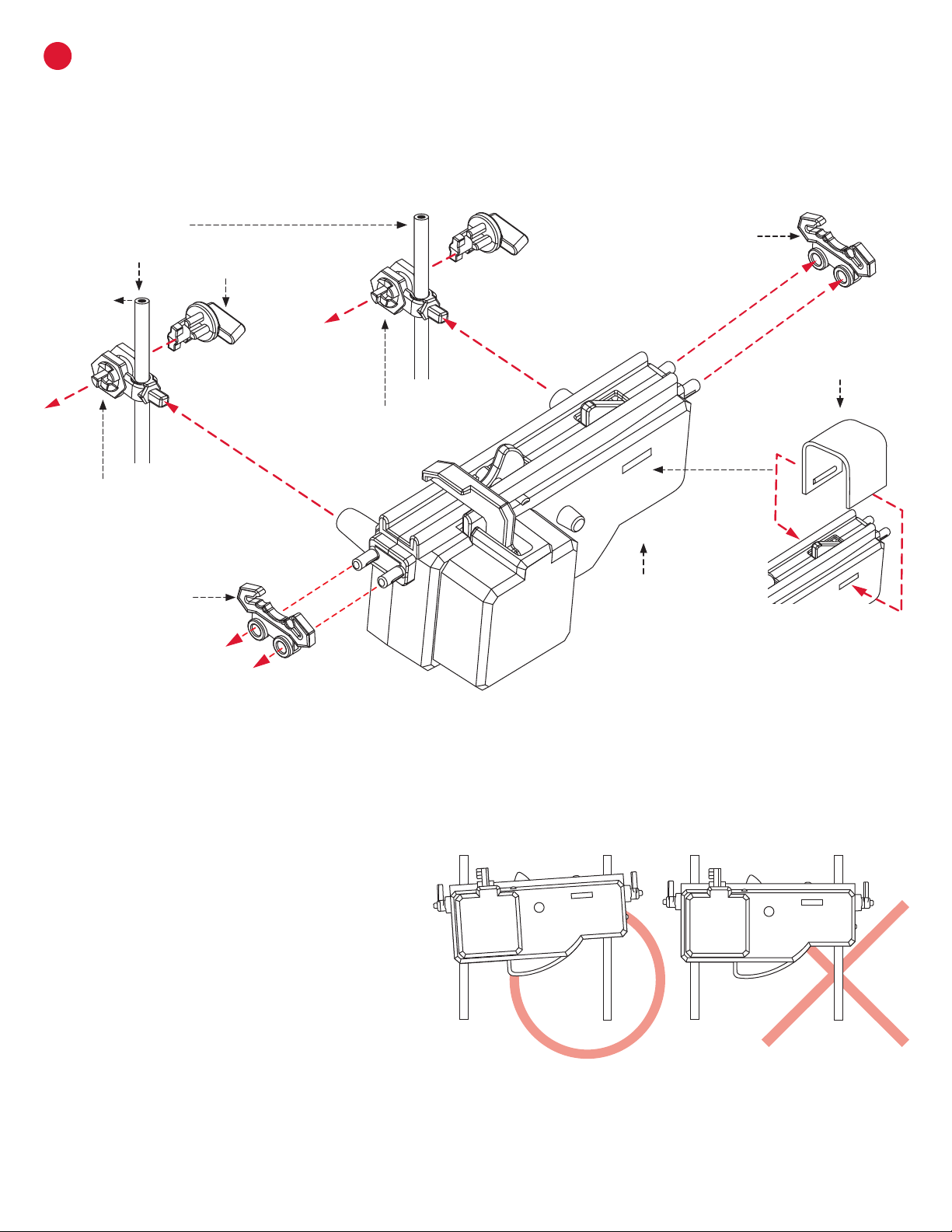
GSTART BLOCK ASSEMBLY
Step 1: Assemble parts as illustrated.
Step 2: Snap the Start Block Cover
on the Start Engine as shown.
Step 3: When positioning the Start Block on the
300mm Shafts, tilt the right (narrower) side up
slightly to encourage smoother operation.
300mm Shaft Rail Clip
Start Block
Start Block Cover
Arm Holder B
Arm Holder B
Rail Clip
Seaich Corporation, LLC. All rights reserved. www.seaich.com |Spacerails, LLC. www.spacerails.com Page 9
FRONT BACK
Rotation
Assembly Start Block
Assembly
Elevator
Assembly
Shaft Connector
(90mm)
Shaft Connector
(154mm)
Shaft Connector
(176mm)
D
B
A
C
E
H
G F
IJ
KL
M
N
OP
Q
R
S
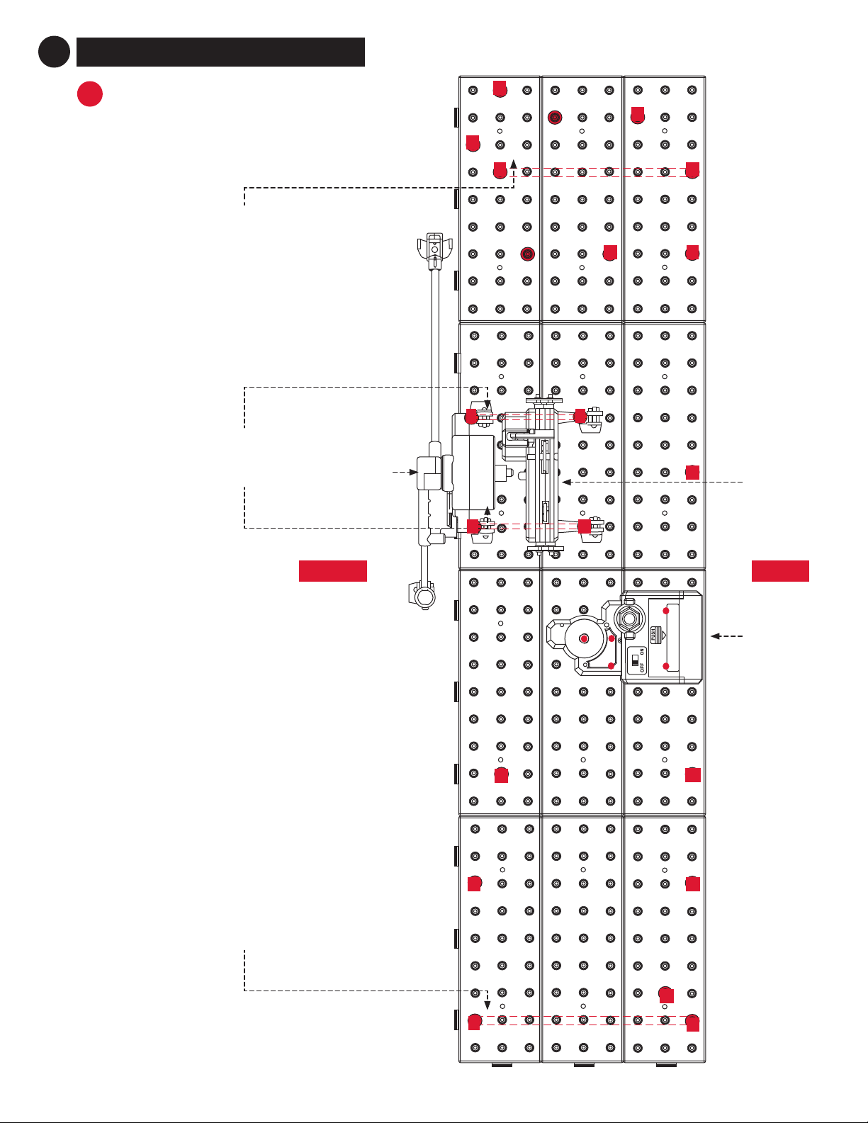
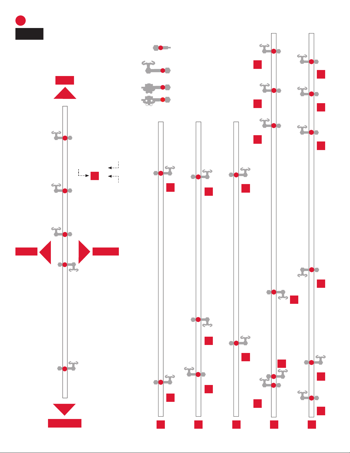
CONSTRUCTING THE COASTER
AINSTALL THE COASTER
SHAFTS, ROTATION ASSEMBLY
AND ELEVATOR
2
Page 10 Seaich Corporation, LLC. All rights reserved. www.seaich.com |Spacerails, LLC. www.spacerails.com
Illustration of shafts are 1:64, or approximately 60% of scale
NOTE:
Arm Holder B
Arm Assembly
See-Saw Assembly (back)
See-Saw Assembly (front)
Each rail connection to the Arm Clips is
labeled according to their shaft letter and
placement on the shaft from the bottom up.
Shaft (391mm)
Shaft (300mm)
19mm
29mm
35mm
41mm
43mm
55mm
75mm
99mm
127mm
150mm
244mm 246mm
248mm
289mm
296mm
318mm
322mm
361mm
372mm
DB
AC E
A-1
A-2
B-1
B-2
B-3
C-1
C-2
D-1
D-2
D-3
D-4
E-1
E-2
E-3
D-5
D-6
E-4
E-5
E-6
BSHAFT ASSEMBLY
FRONTBACK
BOTTOM
TOP
Shaft
letter
Order placement
from bottom
A-1
35mm
Placement
on shaft
Seaich Corporation, LLC. All rights reserved. www.seaich.com |Spacerails, LLC. www.spacerails.com Page 11
Shaft (300mm) Shaft (300mm)
Shaft (391mm)
22mm 26mm
30mm
43mm 50mm
76mm
99mm
124mm
127mm
247mm
249mm
250mm
265mm
289mm
296mm
308mm
329mm
374mm
56mm
202mm
257mm
265mm
Start Block Assembly
Rotation Assembly
HGF I J K L
F-1
F-2
F-3
G-1
G-2
G-3
G-4
G-5
H-1
H-2
H-3
H-4
H-5
H-6
I-1
I-2
I-3 J-1
K-1
K-2
L-1
L-2
Shaft Connector
Assembly
Measure each section and
mark with a pen for placement.
Adjust positions as necessary
when adding rail lines. Be sure
to unlock the Arm Locks before
moving supports.
Page 12 Seaich Corporation, LLC. All rights reserved. www.seaich.com |Spacerails, LLC. www.spacerails.com
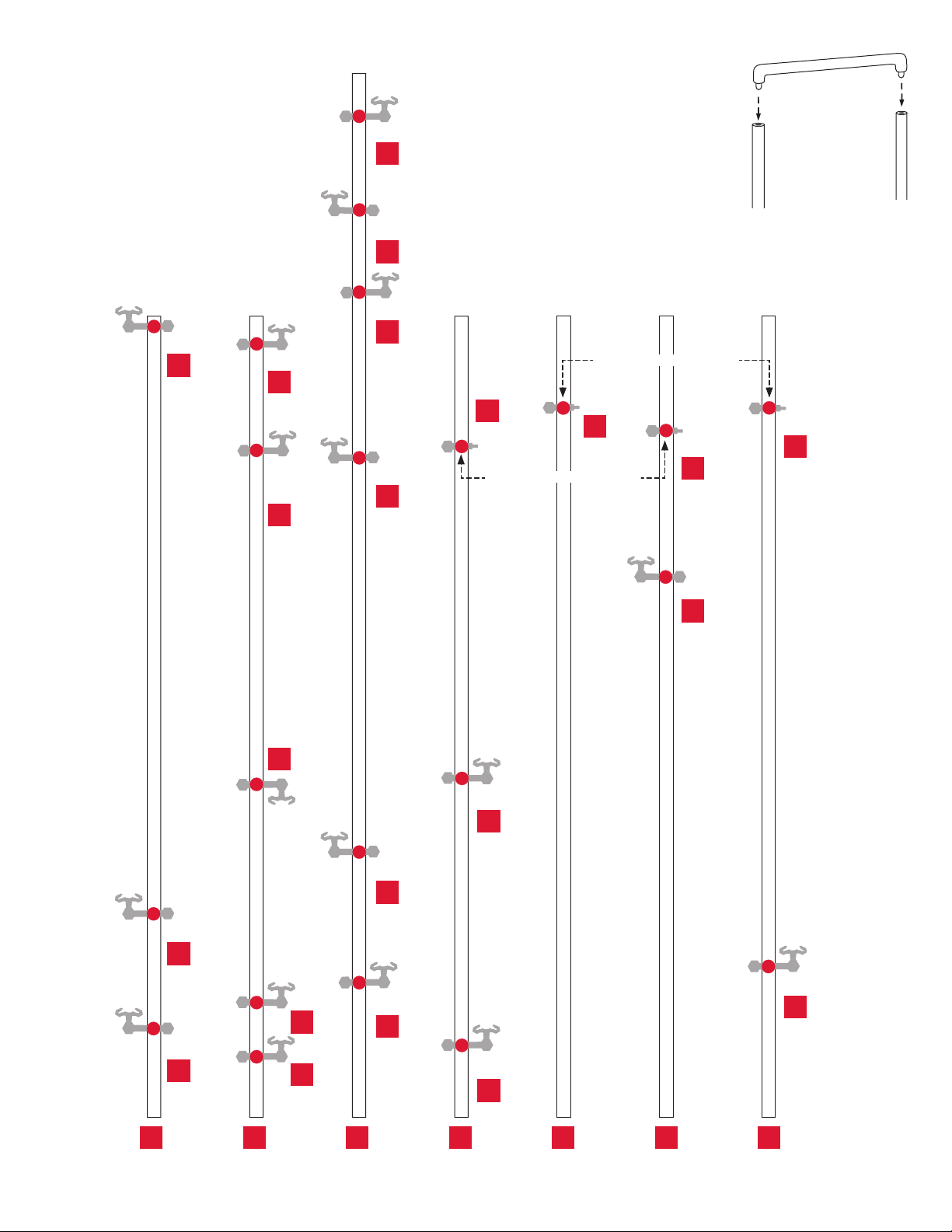
Shaft (200mm)
15mm
27mm
37mm
62mm
71mm
75mm
80mm 83mm
96mm
112mm
117mm
125mm
137mm
142mm
154mm 157mm
172mm
175mm
191mm 195mm
205mm
215mm 219mm
238mm 244mm 249mm
267mm
279mm
289mm 293mm
300mm
306mm
331mm
338mm
356mm
364mm 365mm
366mm
Shaft (391mm)
Shaft (300mm)
M N O P Q R S
N-1
-1
M
-2
M
-3
M
-4M
-5
M
-6
M
N-2
N-3
N-4
N-5
N-6
N-7
N-8
N-9
O-1
O-2
P-1
P-2
P-3
-1
Q
-2
Q
-3
Q
-4
Q
R-1
R-2
R-3
R-4
R-5
R-6
S-1
S-2
S-3
S-4
S-5
S-6
S-7
S-8
Shaft (391mm)
Seaich Corporation, LLC. All rights reserved. www.seaich.com |Spacerails, LLC. www.spacerails.com Page 13
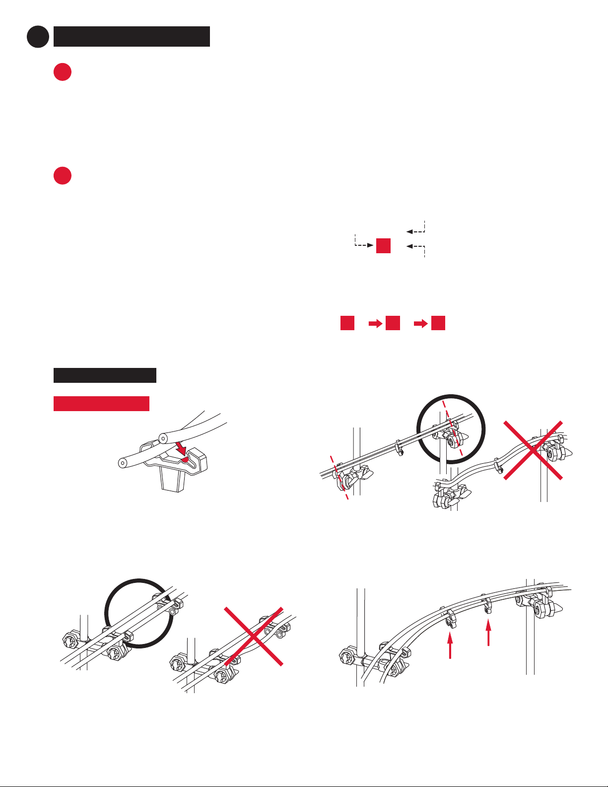
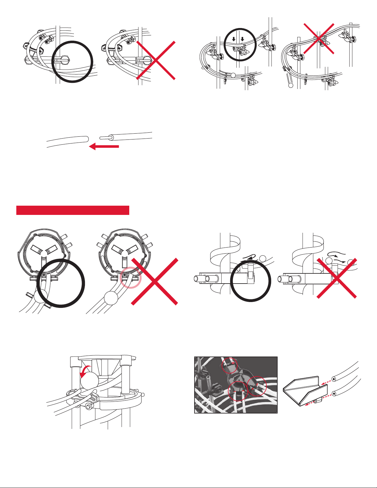
Connecting rails to arms: To install the rails, press
them into the Arm Clips or Rail Clips as shown. You
should hear a click when the rail is locked in place.
Angling the arms: Install the arms at the angle of the
incline the rails will travel along.
Railroad stability: To maintain stability on longer track
segments, attach Rail Clips as needed.
TIPS AND TRICKS
RAIL ASSEMBLY
Step 1: Measure each rail section (lengths are noted under
each diagram) and mark the cutting point with a pen.
Step 2: Cut each rail section according to your
measurement. Make sure to cut at a 90° angle.
Tip: To help avoid do-overs and using too much rail,
cut generously (slightly longer than required) to
begin with. You can always cut a long rail shorter.
Step 1: Start at the top of each section and work your
way downward. You are using gravity to roll the Marbles
downhill.
Each rail connection to the Arm Clips is labeled
according to their shaft letter and placement on the
shaft from the bottom up.
Step 2: The order in which you will connect the rails to
the Arm Clips is indicated by the arrows between each
shaft letter/placement.
C-1A-1 B-1
Shaft
letter
Order placement
from bottom
A-1
35mm
Placement
on shaft
Smooth rails for ecient travel: Make sure the rails
connect smoothly and are free of any bumps, twists,
or kinks.
A
B
CUTTING RAILS TO FIT
RAIL INSTALLATION
CONSTRUCT THE RAILS
3
Page 14 Seaich Corporation, LLC. All rights reserved. www.seaich.com |Spacerails, LLC. www.spacerails.com
Angle curves: Angle the curves inward to help keep the
Marble on the track.
When installing the elevator entry rails, make sure that
the rails don’t dip before entering the elevator.
Elevator entry: When installing the elevator entry rails,
make sure that the rails are angled perpendicular to the
elevator entry point.
Curve stability: To maintain stability on track curves, place
a dip before the curve starts. This will keep the Marbles
from falling o the tracks.
Rail joining for custom designs: To adjust your designs
with the rails, use the Rail Couplings to increase the length
of your rail sections.
Connect Rail Splitters and Pendulum Tray to rails using the
Rail Clips.
Elevator exit: When installing the elevator exit rails, pull the
rails close to the Elevator Helix to ensure the Marble enters
the rollercoaster smoothly.
CONNECTING TO COMPONENTS
Seaich Corporation, LLC. All rights reserved. www.seaich.com |Spacerails, LLC. www.spacerails.com Page 15
LOOP BUILDING
Inclines leading into rail loops must have a high degree, or
the Marble will not traverse the loop.
high
degree of
incline
Inner loop
Rail loops must be “beautiful” circles, or the Marble will not
traverse the loop.
Outer rail loops must be larger than the inner loops, or the
Marble will not traverse the loops.
Inner loop
outer loop

Page 16 Seaich Corporation, LLC. All rights reserved. www.seaich.com |Spacerails, LLC. www.spacerails.com
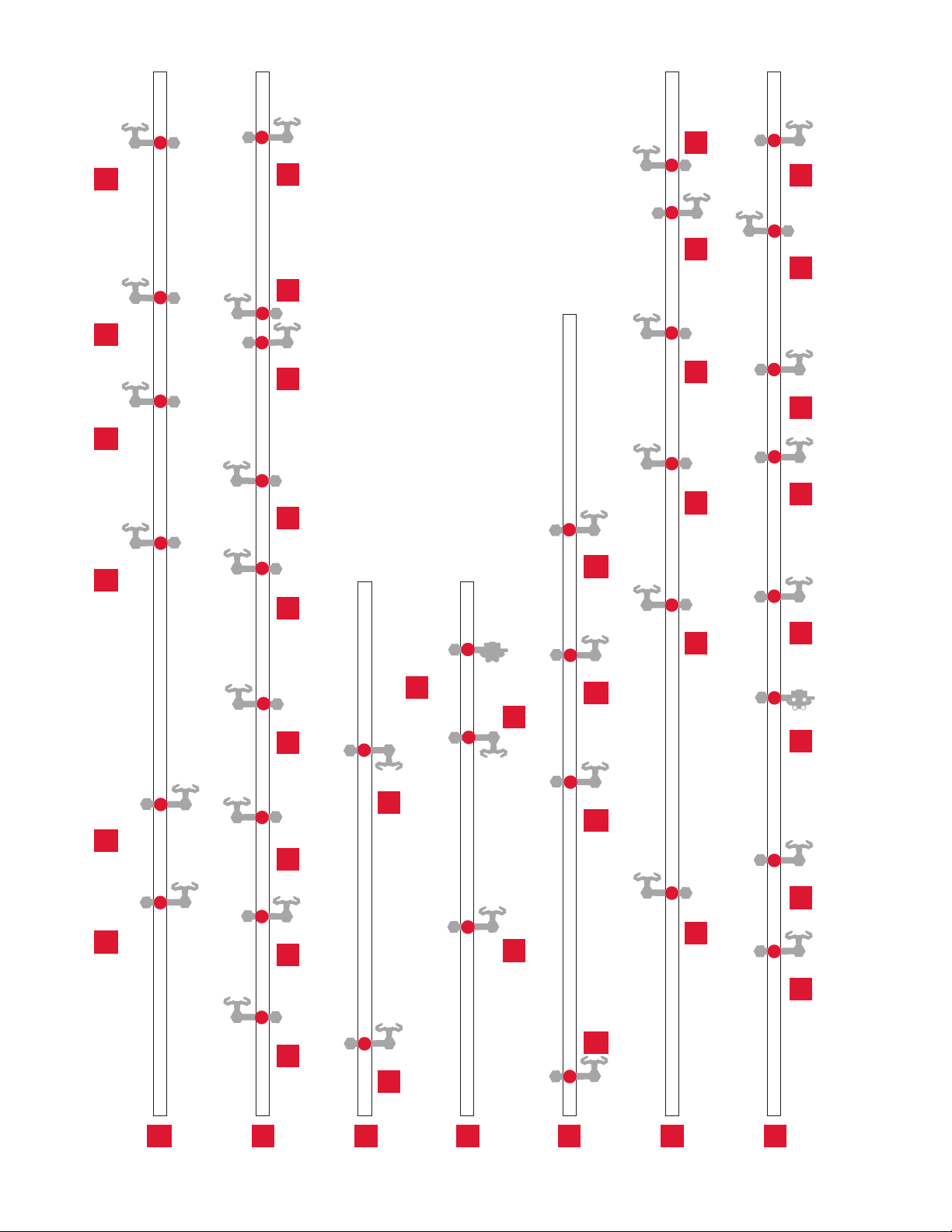
CRAIL ASSEMBLY
Rail Splitter A
M-5 R-5 R-4
S-6S-7N-7N-1L-1
T-3
T-1A-2 C-2
B-3
G-4
Elevator Exit 1 to Rail Splitter A
61cm Rails x 2
Rail Splitter A to Branch A
117cm Rails x 2
Lead Into Pendulum
58cm Rails x 2
Pendulum to Elevator Entry 1
40cm Rails x 2
R-5 S-7T-3 M-5 R-4 S-6N-7 A-2C-2 B-3 G-4 N-1L-1 T-1
SEE INCLUDED INSERT FOR 1:1 SCALE RAIL LENGTHS.
B-1 D-3 D-2
G-3
G-1 G-2 H-1 T-1
B-2
E-3
C-1 E-1 I-2 N-8
Rail Splitter A
Elevator Exit 1 to Rail Splitter A
61cm Rails x 2
Rail Splitter A to Branch A
117cm Rails x 2
Lead Into Pendulum
58cm Rails x 2
Pendulum to Elevator Entry 1
40cm Rails x 2
(Not to scale)
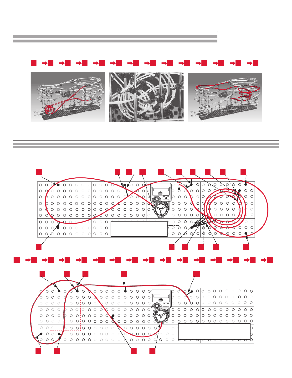
Seaich Corporation, LLC. All rights reserved. www.seaich.com |Spacerails, LLC. www.spacerails.com Page 17
Rail Splitter A To Loop And Elevator Entry 2
270cm Rails x 2
B-1D-3D-2G-3G-1 G-2 H-1 T-1B-2E-3 C-1E-1I-2N-8
Elevator Exit 2 To Transverse Loop (beginning part)
487cm Rails x 2 (continues to second part below)
Q-4
N-6S-5
M-4
H-4 Q-3 N-4 Q-2
R-3E-6 N-5D-6H-6
T-3 N-3 M-2
Q-4
N-6 S-5
M-2H-4 Q-3
N-3
Q-2 R-3
E-6 N-5
D-6 H-6 T-3
N-4
M-4
Continues below.
Do not cut/separate rails!
M-2
A-1 I-1
F-2D-1
E-2 T-1
F-1 H-2
Continued from above.
Do not cut/separate rails!
Elevator Entry 3
(Not to scale)
Rail Splitter A To Loop And Elevator Entry 2
270cm Rails x 2
Elevator Exit 2 To Transverse Loop
487cm Rails x 2

Page 18 Seaich Corporation, LLC. All rights reserved. www.seaich.com |Spacerails, LLC. www.spacerails.com
M-2 F-2 D-1H-2 A-1E-2
F-1 I-1 T-1
Elevator Exit 2 to Transverse Loop (end part)
487cm Rails x 2 (continued from rst part on previous page)
M-1
P-2
R-1
T-2 S-2
Elevator
Entry 4
Connect Pendulum Tray to beginning of
rail loop.
M-1
P-2 R-1 T-2
S-2
M-3
E-5
H-3
S-6
R-2
G-5
N-9
E-4
M-6
E-5
T-3
D-4
R-6
D-5
S-8
H-5
F-3
Rail Splitter B to See-Saw 1
96cm Rails x 2
Elevator Exit 3 to Rail Splitter B
235cm Rails x 2
Pendulum Tray to Elevator Entry 4
80cm Rails x 2
S-4 S-8N-9T-3E-5 G-5
M-3M-6 R-2H-3D-5D-4
E-4
R6H-5F-3
Rail Splitter B See-Saw
See-Saw 2 See-Saw 1
S-4H-3
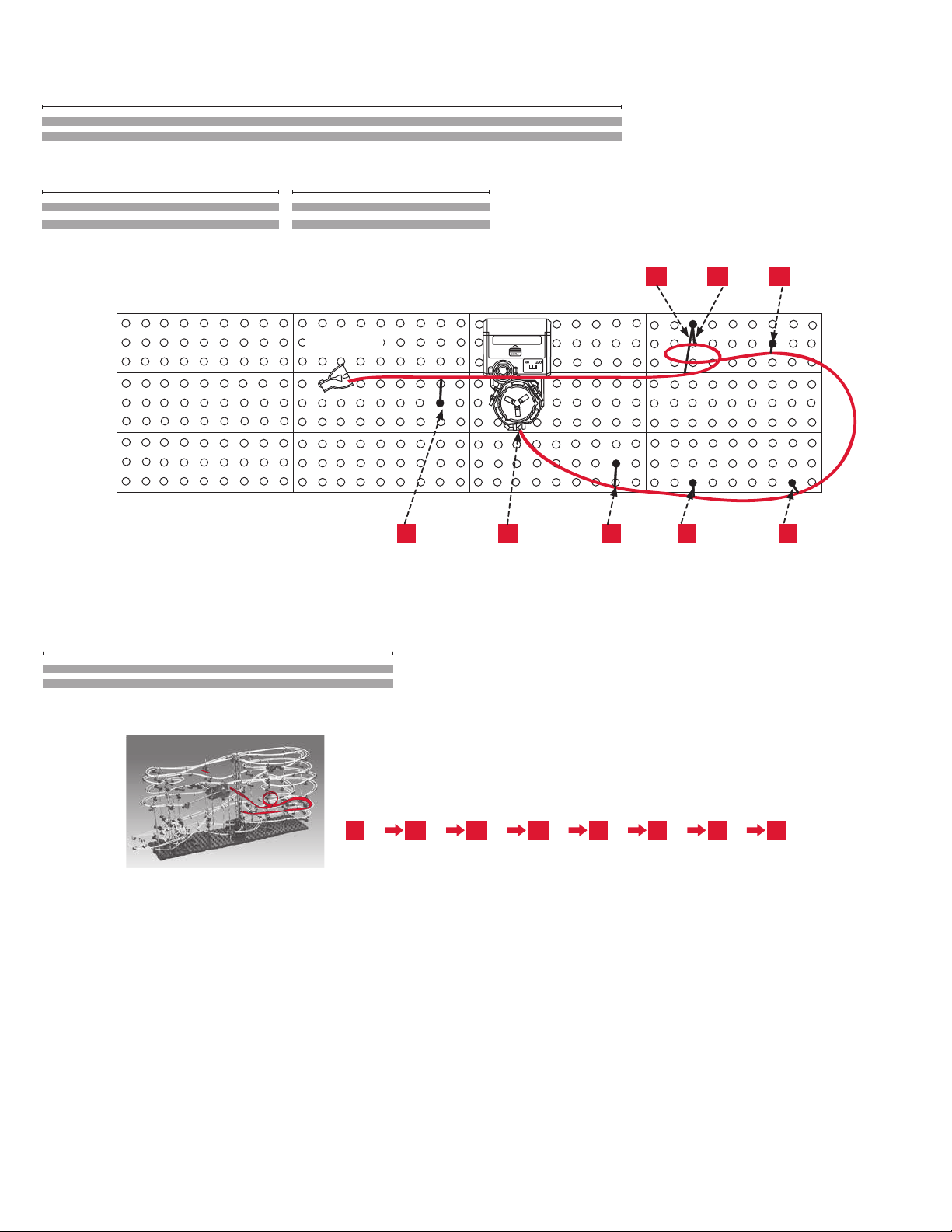
Seaich Corporation, LLC. All rights reserved. www.seaich.com |Spacerails, LLC. www.spacerails.com Page 19
P-1 S-1K-1 T-1 N-2
O-1 O-2 Q-1
Rail Splitter B
Rail Splitter B to Elevator Entry 5
42cm Rails x2
O-2 O-1 Q-1 P-1S-1K-1 T-1N-2
Rail Splitter B to Elevator Entry 5
142cm Rails x 2
(Not to scale)
Elevator Exit 3 to Rail Splitter B
235cm Rails x 2
Rail Splitter B to See-Saw 1
x2 96cm Rails
Pendulum Tray to Elevator Entry 4
80cm Rails x 2
(Not to scale)

Seaich Corporation
1910 West 1040 South
Salt Lake City, UT 84104
(833) 732-4242
Spacerails LLC
www.spacerails.com
Table of contents
Other Spacerails Toy manuals

Spacerails
Spacerails Level 7 User manual

Spacerails
Spacerails Level 3 User manual

Spacerails
Spacerails Level 2 User manual

Spacerails
Spacerails Level 8 User manual

Spacerails
Spacerails LEVEL 4 User manual

Spacerails
Spacerails Level 9 User manual

Spacerails
Spacerails Level 1 User manual

Spacerails
Spacerails LEVEL 6 User manual


