Spacerails LEVEL 6 User manual

LEVEL 6
PRODUCT AND CONSUMER WARNING
CHOKING HAZARD: This product contains small parts and is not intended for children under 3.
• This product is intended for users 8 years of age and older.
• To avoid choking, keep small parts away from children.
• Use caution—this product contains parts with sharp edges.
• To avoid potential damage to the product, only insert the included marbles into the elevator.

Page 2 Seaich Corporation, LLC. All rights reserved. www.seaich.com |Spacerails, LLC. www.spacerails.com
PARTS INCLUDED
Keep parts together to avoid misplacing them.
ARM COMPONENTS
Arm Clip
x125
Arm Sheath
x136
Arm Holder A
x125
Arm Holder B
x140
Arm Lock
x256
Shaft Connector
(176mm) x5
Shaft Connector
(154mm) x3
BASE COMPONENTS
Base Base Holder A Base Holder B
x16 x14 x9
RAIL COMPONENTS
Rail Clip
x150
Rail Coupling
10 PCS
Marble
8 PCS
Rail
60,000 mm
RECOMMENDED TOOLS & ITEMS (NOT INCLUDED)
Wire Cutters or Utility Scissors
Pen or Marker
3 AA Batteries (newer models) or 1 C Battery
Ruler (in centimeters)
ELEVATOR COMPONENTS
Power Box
x1
Elevator Helix
x16
Elevator Ring
x3
Elevator Cover
x1
Elevator Guard
x9
Power Box Stand
x1
SHAFT COMPONENTS
Rail Splitter
x3
See-Saw Arm
x7
SPLIT AND SEE-SAW COMPONENTS
Shaft (391mm)
x18
Shaft (300mm)
x6
Shaft (200mm)
x2

Seaich Corporation, LLC. All rights reserved. www.seaich.com |Spacerails, LLC. www.spacerails.com Page 3
1PREPARE ARMS AND RAIL SPLITTER
Cut two 55 mm lengths of
rail and insert into See-Saw
as shown using a Rail Clip to
support the ends of the rail.
B
AARM-A QTY: 135 SHAFT TO RAIL
Step 1: Attach one Arm Holder A and one
Arm Holder B with one Arm Sheath. Insert
one Arm Clip into Arm Holder A.
Step 3: Turn the Arm Lock
counter-clockwise to secure
the Arm Clip in place.
Step 2: Insert Arm Lock through
Arm Holder A and Arm Clip.
To avoid damaging parts, do not move or adjust the Rail Clip while locked in the arm. To move the Rail Clip, release
Arm Lock by turning clockwise, position Rail Clip as desired, then secure Arm Lock again.
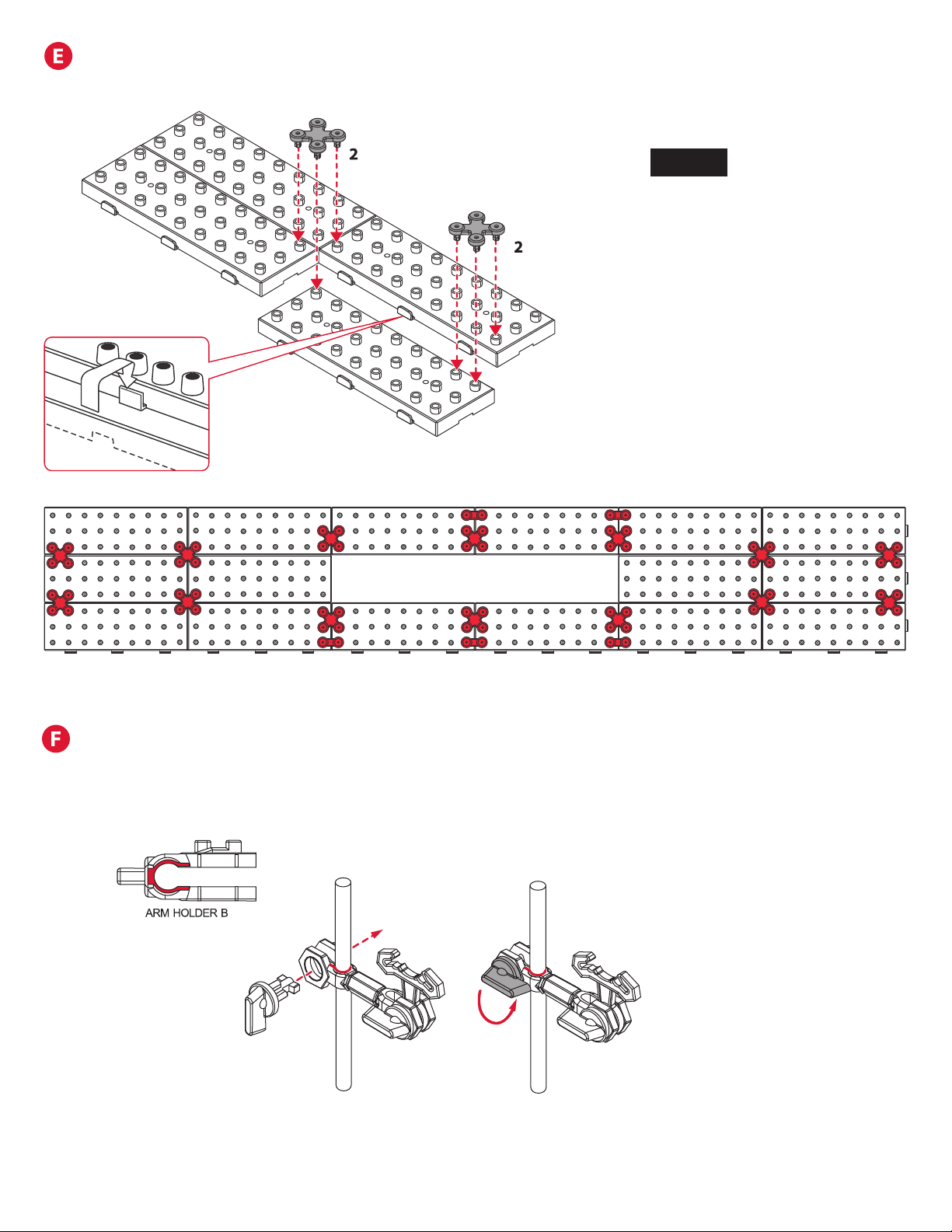
Attach Arm Holder B to the square receiver side of Arm Sheath to
create the arm. Attach the arm to the shaft and the shaft to the
base prior to attaching the round receiver side of the Arm Sheath
to the See-Saw Arm. (See page 15)
SEE-SAW ARM QTY: 4 LEFT & 3 RIGHT
Attach one Arm Holder B on each side
of the Arm Sheath.
ARM-B QTY: 4 SHAFT TO SHAFT
RAIL SPLITTERS
Step 1: Attach one Rail Clip on each
of the Rail Splitter posts.
D
C
Page 4 Seaich Corporation, LLC. All rights reserved. www.seaich.com |Spacerails, LLC. www.spacerails.com
Step 1: Interlock
all Base block tabs
as shown below.
Step 2: Press Base Holder A and
Base Holder B pieces into the Base
blocks for a more secure hold.
Illustration of base with tabs
locked and Base Holders installed.
Approximately 17% of actual size.
Step 1: Slide Arm Holder B of each arm on to a shaft and lock in place with Arm
Lock. Refer to the next page for orientation and location of each arm.
SHAFT ASSEMBLY
NOTE:
Please see the included full size
drawings for the next several steps.
This will simplify the positioning of
the base, arms, shafts, and the rail
cut lengths.
BASE ASSEMBLY
Seaich Corporation, LLC. All rights reserved. www.seaich.com |Spacerails, LLC. www.spacerails.com Page 5
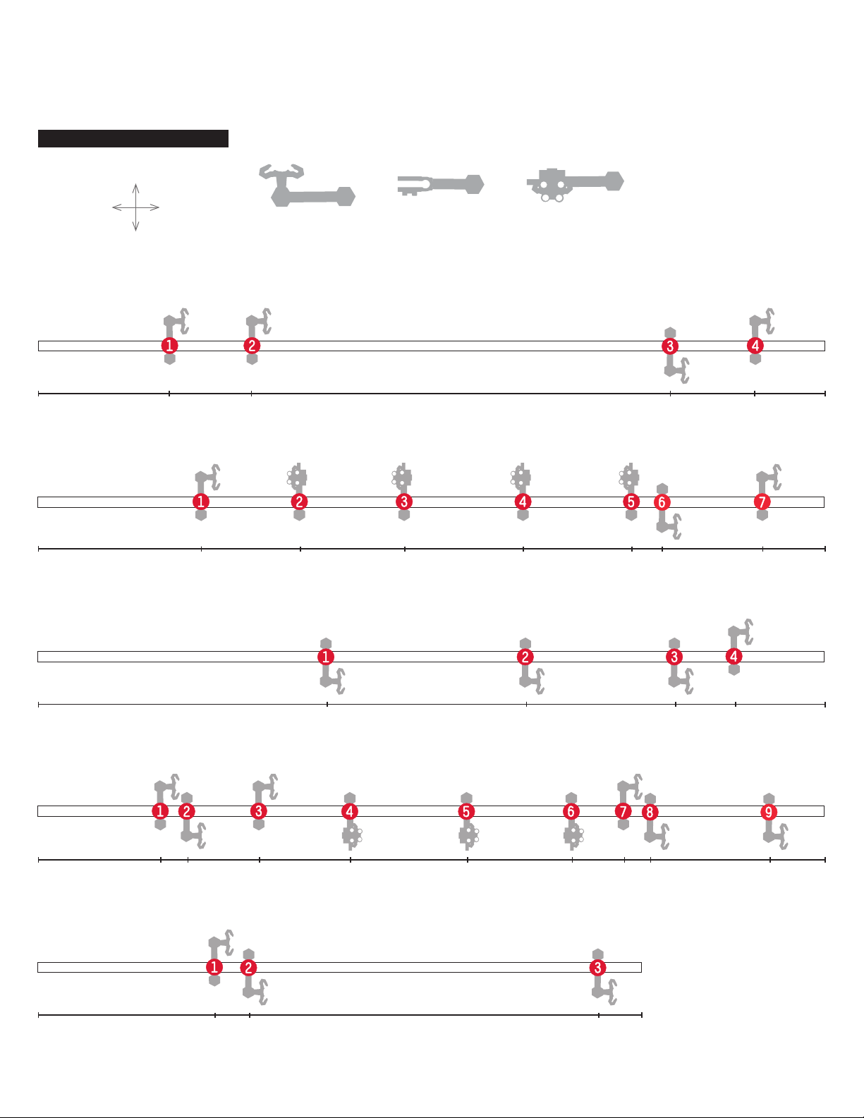
This is how the arm types are referenced on the shaft drawings.
Arm A Arm B See-Saw Arm
Step 2: Attach each arm as shown in step 1 with the orientation and location shown here. In later steps the letter of each
shaft and number of each arm will guide in the installation of the rails. For example arm A-3 below is 314 mm from the
base and faces the front. Illustration is approximately 50% of actual size. All shaft measurements are in Millimeters.
Shaft A
Shaft B
Shaft C
Shaft D
Shaft E
65
81 130
143
63
88 105 278
73 110 156 213 265 291 303 363
242 316 346
182 241 295 310 360
106 356314 391
391
391
391
300
TOP
BASE
BACK
OF BASE
FRONT
OF BASE
SHAFT TO BASE ORIENTATION
Page 6 Seaich Corporation, LLC. All rights reserved. www.seaich.com |Spacerails, LLC. www.spacerails.com
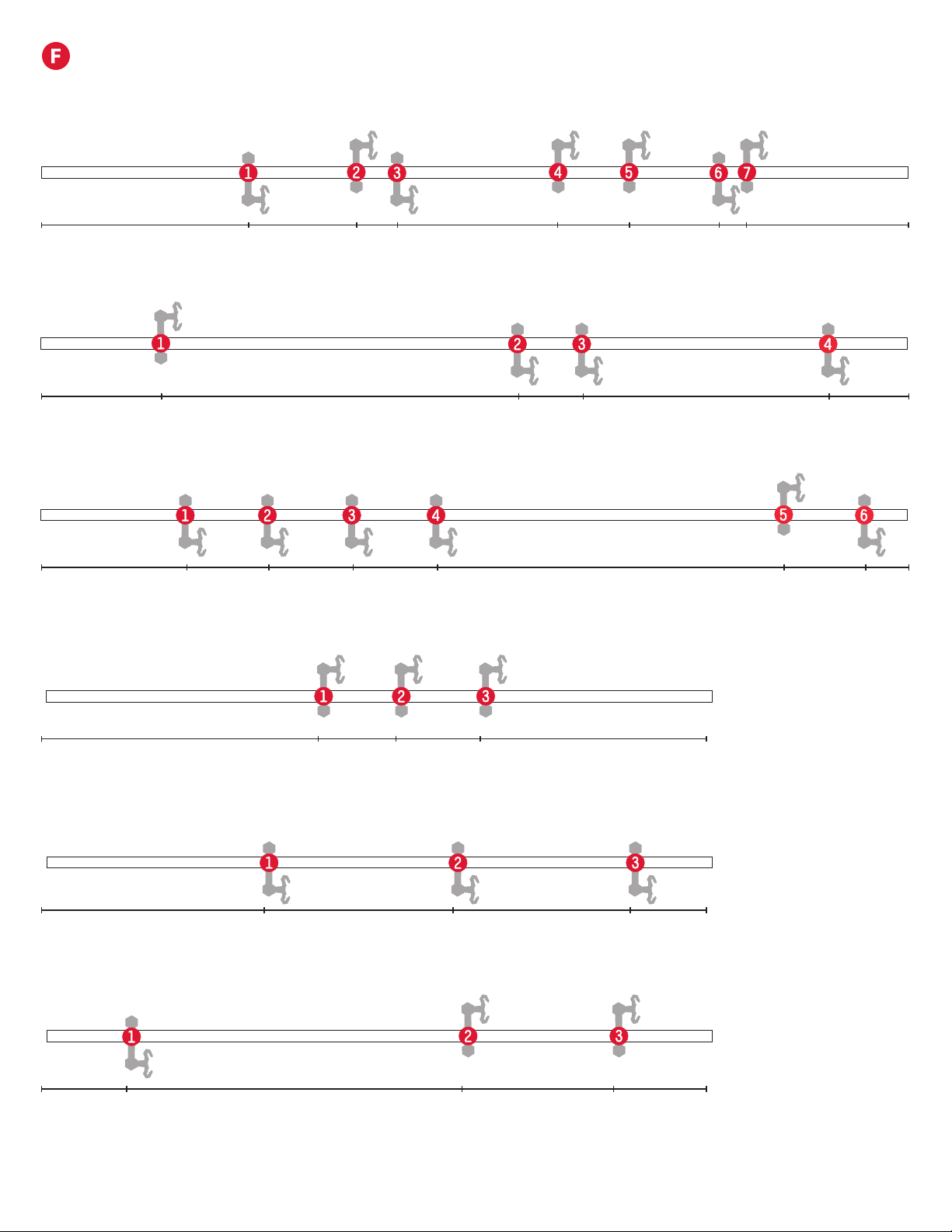
SHAFT ASSEMBLY CONTINUED
Shaft F
Shaft G
Shaft H
Shaft I
Shaft K
Shaft J
93 142 160 233 265 305 317
93 215 244 355
65 102 140 177 335 371
100 185 265
125 165 198
38 190 258
391
391
391
300
300
300

Seaich Corporation, LLC. All rights reserved. www.seaich.com |Spacerails, LLC. www.spacerails.com Page 7
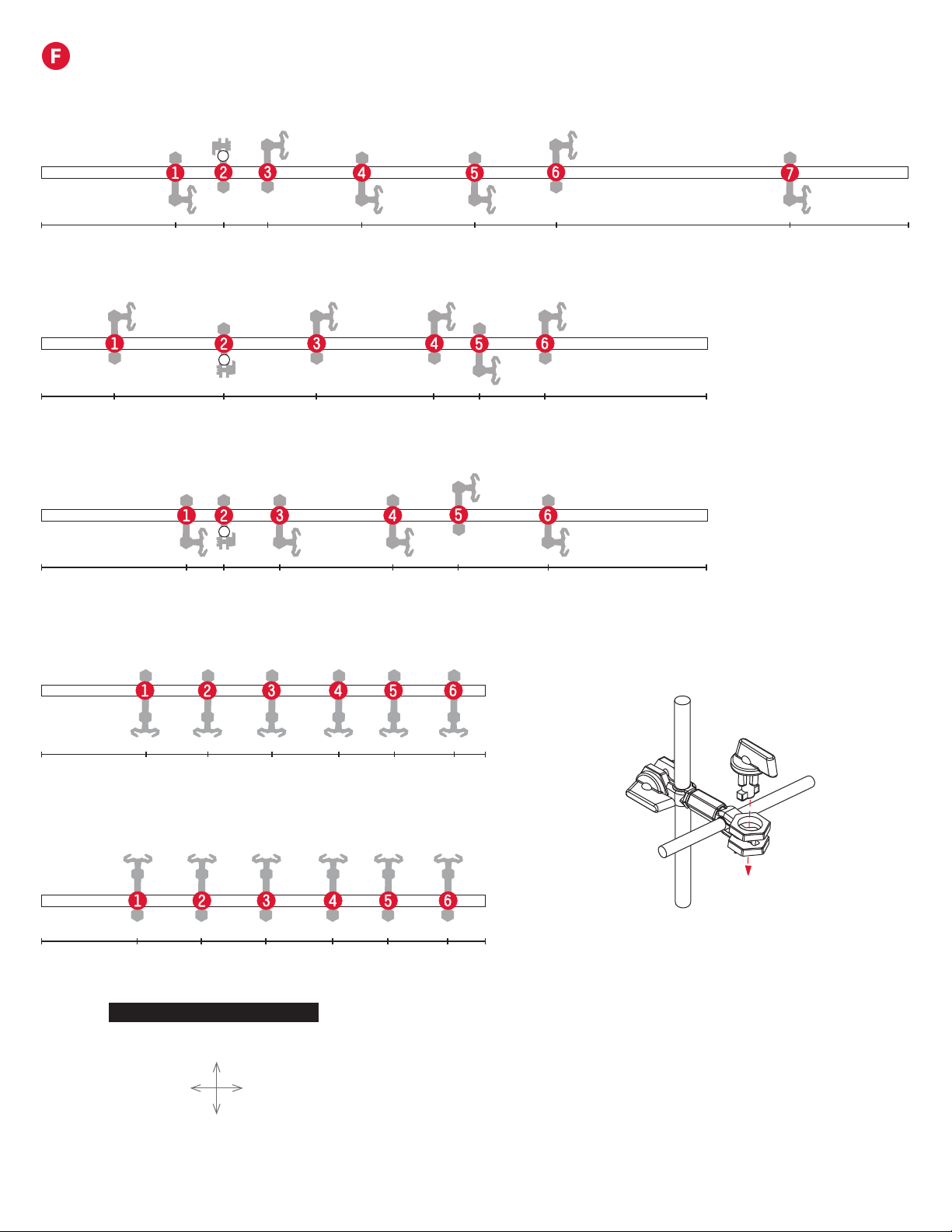
SHAFT ASSEMBLY CONTINUED
Shaft L
Shaft M
Shaft N
Shaft O
Shaft Q
Shaft P
81 92 178 224 283 322 359
49 67 162 213 260 293 313 330 342
69 115 142 180 218 250 286 326
57 69 117 158 174 191 226 260 298 224 336
63 99 141 178 216 251 288 323
82 109 132 179 280 332
391
391
391
391
391
391
Page 8 Seaich Corporation, LLC. All rights reserved. www.seaich.com |Spacerails, LLC. www.spacerails.com
Shaft V and Shaft W are
suspended above the base
using Arm B connections
from shafts Q, R, S, and T.
SHAFT ASSEMBLY CONTINUED
Shaft R
Shaft S
Shaft T
Shaft V
Shaft W
60 82 102 144 195 232 337
43 72 101 131 156 183
47 75 104 134 159 186
391
200
200
33 83 124 177 197 227
65 83 107 158 188 228
300
300
TOP
BASE
BACK
OF BASE
FRONT
OF BASE
SHAFT TO BASE ORIENTATION

Seaich Corporation, LLC. All rights reserved. www.seaich.com |Spacerails, LLC. www.spacerails.com Page 9
Step 3: Once the Corkscrew
is built, attach three support
shafts to the Power Box.
Step 1: Place a 391 mm
Shaft in the white hole on
the Power Box.
ELEVATOR ASSEMBLY
Illustrations are approximately 33% of actual size.
Step 2: Connect Elevator
Helix pieces together with
the male part facing up to
ll the shaft. Step 4: Slide each Elevator
Ring into position on the
support shafts right-side up.
NOTE:
The Marble may
fall out of the
elevator if it
enters too fast.
Step 7: Insert three Elevator Guards each
in the bottom two Elevator Rings.
Step 5: Place the Elevator
Cover onto the top of the
elevator assembly.
NOTE:
Elevator Rings are
right-side up when tabs in
red are on the top.
NOTE:
Install the rst
Elevator Helix
piece male side up
and rotate it until
it slides in place
and engages with
driver at the base
of Power Box.
Step 6: Attach Rail Clips
to each Elevator Ring
as shown.
347 mm
32 mm

Page 10 Seaich Corporation, LLC. All rights reserved. www.seaich.com |Spacerails, LLC. www.spacerails.com
CUT THE RAIL TO SIZE
15 cm
a
b
27 cm
c
36 cm
d
75cm
e
100cm
f
341 cm
g
410 cm
h
480 cm
i
495 cm
j
550 cm
Step 1: Measure each section and mark the cutting point with a pen. Rail measurements
are in Centimeters.
Step 2: Cut each section according to your measurement. Make sure to cut at a 90° angle.
Tip: To help avoid do-overs and using too much rail, cut generously (slightly longer than
required) to begin with. You can always cut a long rail shorter.
NOTES:
Illustration of rail lengths is 3% of actual size.
Please see the included full size drawings. This will simplify the
positioning of the base, arms, shafts, and the rail cut lengths.
G

Seaich Corporation, LLC. All rights reserved. www.seaich.com |Spacerails, LLC. www.spacerails.com Page 11
INSTALL ELEVATOR AND SHAFTS TO BASE
Illustrations are approximately 28% of actual size.
Step 1: Attach Power Box Stand to the Power Box.
Step 2: Firmly seat the posts from the Power Box
in the holes on the base.
Step 3: Use diagram on the Right for location
of each shaft. Push shaft into holes on base
until sturdy. Refer to drawings on pages 5-8 for
orientation to install shafts.
Step 4: Install shaft
connectors (dashed red lines)
to help stabilize shafts as rails
are installed and tension
is increased.
Posts attach
to Base
2CONSTRUCTING THE ROLLER COASTER
A
NOTE:
Shaft V and shaft W are suspended above the base using
Arm B connections from shafts Q, R, S, and T.
FRONT
OF BASE
BACK
OF BASE
SHAFT TO BASE ORIENTATION
Shaft
Connectors
Page 12 Seaich Corporation, LLC. All rights reserved. www.seaich.com |Spacerails, LLC. www.spacerails.com
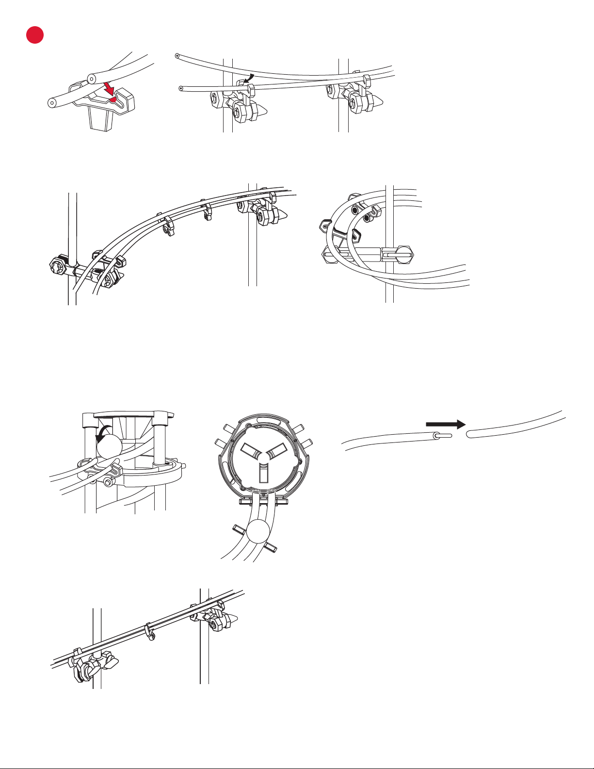
BTIPS FOR INSTALLING RAILS
Connecting rails to arms: To install the rails, press them into the arm as
shown. You should hear a click when the rail is locked in place.
When building a curved rail, Clips and Arm Clips can be
adjusted to create a banked curve. Plenty of Rail Clips
are included so that they can be applied liberally.
Attach Rail Clips every 8-10 cm along rail
to maintain stability and keep rails parallel.
Keeping rails uniform maintains speed and
avoids throwing the Marble o course.
Rails should extend into the elevator
enough to catch the Marble.
Rail Couplings are provided but not needed. If
more length is needed for a rail, insert the coupling
into the end of both rails being joined.
Keep incline as smooth as possible to avoid
losing speed or contact with rails.

Seaich Corporation, LLC. All rights reserved. www.seaich.com |Spacerails, LLC. www.spacerails.com Page 13
BINSTALLING RAIL
Rail Section 1 & 2:
Splitter B
Splitter A
Step1: Install one side of a rail at a time. Starting at the
top Elevator Ring on the Left side Rail Clip connect Rail-E
(100 cm). Keeping Rail tight connect through Arm D-9, B-7,
A-4, C-4, G-4, and H-4. Next attach the Rail to the Rail Clip
on single side of the Rail Splitter B. Repeat this step for the
second rail.
Step2: Starting at the top Right Elevator Ring Rail Clip
connect Rail-A (15 cm). Next attach the Rail to the Rail Clip
on single side of the Rail Splitter A. Repeat for second rail.
Step 3: Attach Rail F (341 cm) to the inside Rail Clip of
Splitter-A facing the front of the Base. Keeping Rail tight
connect through Arm M-8 and down to Arm R-1. Next start
a nested loop where each successive loop is slightly smaller
than the one before it. Continue with the inside rail connect
Arms W-6, V-6, W-5, V-5, W-4, V-4, W-3, V-3, W-2, V-2, W-1,
and V-1. Exit loop to Arm S-1 and continue around coaster
to Arms T-1, R-1, O-2, M-2, and nish at Rail Clip on Elevator
Ring 2 on the right side. Repeat step for second rail.
Fine Tune: Once each Rail Section is completed run a
marble down your course and make sure ball travels well.
Make any adjustments as needed. Do not worry about
adjusting splitter until all Rails have been connected.
Step1:
Step2:
Step3:
NOTE:
Start with a loop of about 10 cm on the front and work
down to about 6 cm on the back loop. These numbers
are intended to be a guide only. Test your loops with
the Marble. Adjust until you get good consistent speed
throughout this section.
Page 14 Seaich Corporation, LLC. All rights reserved. www.seaich.com |Spacerails, LLC. www.spacerails.com
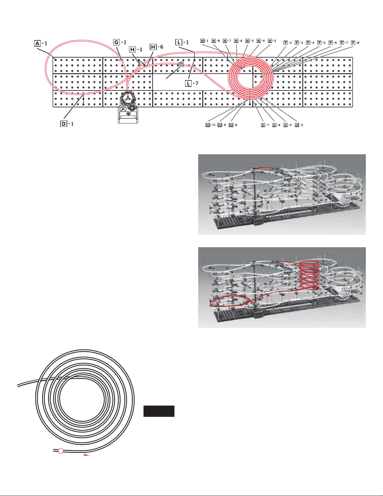
Rail Section 3:
Step1: Starting at the top Elevator Ring connect Rail-B
(27 cm) to Rail Clip at the back. Keeping Rail tight connect
through Arm H-6 and attach the Rail to the Rail Clip on single
side of the Rail Splitter C. Repeat for second rail.
Step2: Start by attaching Rail H (480 cm) to the inside Rail Clip
of Splitter-C facing the front of the Base. Keeping Rail tight
connect through Arm L-7. Next start a vertical nested loop
where each successive loop is slightly smaller than the one
before it beginning with Arm O-11. Continue with Arms P-8,
N-8, O-9, P-7, N-7, O-8, P-6, N-6, O-7, P-5, N-5, O-6, P-4, N-4,
O-4, P-3, N-3, O-3, P-2, and exit loop to Arm N-1. Continue to
exit through Arms L-1, H-1, D-1, A-1, and G-1. Finish at Rail
Clip on Elevator Ring 1 at the back of the elevator. Repeat
step for second rail.
Step1:
Step2:
NOTE:
If length of rail is longer or shorter than
expected try adjusting the size of the nested
loops to better utilize the rails.
This top view of the nested loop section shows how each successive loop is
slightly smaller than the one above it. Start with a loop of about 20 cm and
work down to about 17 cm on the bottom loop. These numbers are intended
to be a guide only. Test your loops with the Marble. Adjust until you get good
consistent speed throughout this section.
Splitter C

Seaich Corporation, LLC. All rights reserved. www.seaich.com |Spacerails, LLC. www.spacerails.com Page 15
Rail Section 4:
Step 1: Start by attaching Rail D (75 cm) to the inside Rail Clip of Splitter-B facing the front of the Base. Connect through Arm
M-7, F-6, and D-8. Repeat for second rail.
The end of this section drops the Marble onto the See-Saw section. If you have not already attach the See-Saw arms.
The last See-Saw arm will drop the Marble on the exit section that uses Rail C (36 cm) and starts at Arm B-1 and passes
through Arm D-2 entering the left facing rail clip on the bottom Elevator Ring. Repeat for second rail.
Step1:Cut two 55mm lengths
of rail and insert into
See-Saw as shown
using a Rail Clip to
support the ends of
the rail.
Attach Arm Holder B to the square receiver side of
Arm Sheath to create the arm.
Attach the arm to the shaft and
the shaft to the base prior to
attaching the round receiver
side of the Arm Sheath to the
See-Saw Arm.
SEE-SAW ARM QTY: 4 LEFT & 3 RIGHT
Splitter B
Page 16 Seaich Corporation, LLC. All rights reserved. www.seaich.com |Spacerails, LLC. www.spacerails.com
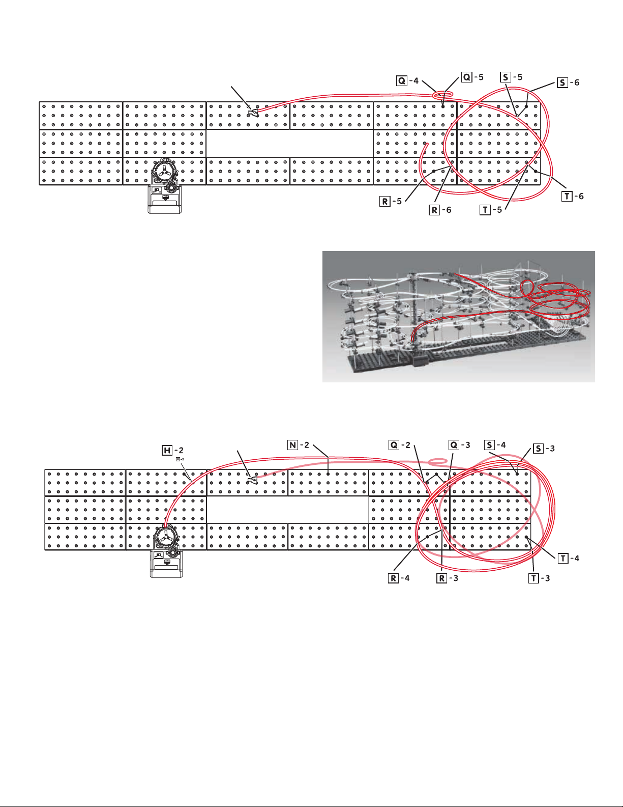
Rail Section 6:
Splitter C
Splitter C
Step1: Start by attaching Rail I (495 cm) to the Rail Clip of
Splitter-C facing the back of the Base. Connect rst to
Arm Q-4 and loop up to Arm Q-5 and shift loop inside
closer to shaft Q and up through Arm S-5. Continue
through Arms T-6, S-6, T-5, and R-5. See next illustration to
continue.
Proceed from Arm R-5 to Arms S-4, T-4, R-4, Q-3, S-3, T-3,
R-3, Q-2, N-2, H2, and enter the back facing rail clip on the
second Elevator Ring. Repeat entire step for second rail.
Step1:

Seaich Corporation, LLC. All rights reserved. www.seaich.com |Spacerails, LLC. www.spacerails.com Page 17
Rail Section 7:
Splitter B
Step1: Start by attaching Rail G (410 cm) to the inside Rail Clip of Splitter-B facing the back of the Base. Connect rst to Arm
L-5 and then create a gure 8 pattern by connecting through M-5, J-3, K-3, L-4, M-4, J-2, L-3, and out to M-3. Continue past
the elevator to F-3, C-1, F-2, E-2, D-3, A-2, E-1, F-1 and enter Elevator Ring 2 on the Left side. Repeat step for second rail.
Step1:
Page 18 Seaich Corporation, LLC. All rights reserved. www.seaich.com |Spacerails, LLC. www.spacerails.com
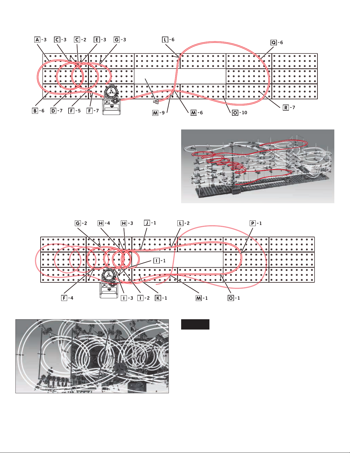
Rail Section 8:
Splitter A
Step1: Start by attaching Rail J (550 cm) to the inside Rail Clip
of Splitter-A facing the back of the Base. Proceed to Arms
L-6, Q-6, R-7, O-10, and M-6. Pass by the elevator and attach
to Arm F-7, B-6, A-3, C-3, D-7, E-3, F-5, and G-3. See next
illustration to continue.
Proceed from Arm G-3 to Arms F-4, G-2, I-3, H-4, I-2, H-3, and
I-1. nish with Arms J-1, L-2, P-1, O-1, M-1, and K-1 and enter
the right facing rail clip on the bottom Elevator Ring. Repeat
entire step for second rail.
Step1:
Overhead view of cascading loops in step 1
NOTE:
Congratulations on completing Spacerails Level 8! Fine
tune the rails and see how many marbles you can get
going at the same time. If the marbles are coming into the
elevator too quickly it may knock other marbles already
in the tower out. Create a dip or nd other ways to slow
marbles to just the right speed at entrance.

Seaich Corporation, LLC. All rights reserved. www.seaich.com |Spacerails, LLC. www.spacerails.com Page 19
3NOTES

Seaich Corporation
1910 West 1040 South
Salt Lake City, UT 84104
(833) 732-4242
Spacerails LLC
Spacerail © 2021
www.spacerails.com
Table of contents
Other Spacerails Toy manuals

Spacerails
Spacerails Level 7 User manual

Spacerails
Spacerails Level 8 User manual

Spacerails
Spacerails Level 9 User manual

Spacerails
Spacerails Level 5 User manual

Spacerails
Spacerails Level 2 User manual

Spacerails
Spacerails Level 1 User manual

Spacerails
Spacerails LEVEL 4 User manual

Spacerails
Spacerails Level 3 User manual
Popular Toy manuals by other brands


Fisher-Price
Fisher-Price Little People HJN40 instructions

PIKO
PIKO SM31 PKP Instructions for use

Eduard
Eduard BRASSIN 632002 F-4B/J/N/S seat 1/32 Assembly manual

AquaCraft
AquaCraft Reef racer 2 Assembly and operation manual

BNF
BNF Blade Fusion 270 instruction manual

Hasbro
Hasbro NERF Marvel Avengers MechStrike instructions