Spacerails Level 8 User manual

LEVEL 8
PRODUCT AND CONSUMER WARNING
CHOKING HAZARD: This product contains small parts and is not intended for children under 3.
• This product is intended for users 8 years of age and older.
• To avoid choking, keep small parts away from children.
• Use caution—this product contains parts with sharp edges.
• To avoid potential damage to the product, only insert the included marbles into the elevator.

Page 2 Seaich Corporation, LLC. All rights reserved. www.seaich.com |Spacerails, LLC. www.spacerails.com
PARTS INCLUDED
Keep parts together to avoid misplacing them.
ARM COMPONENTS
Arm Clip
x80
Arm Sheath
x75
Arm Holder A
x70
Arm Holder B
x90
Arm Lock
x170
SPLIT AND CAPTURE COMPONENTS
Rail Splitter
x2
Capsule Ring
x1
Capsule
x1
BASE COMPONENTS
Base Base Holder A Base Holder B
x12 x10 x8
RAIL COMPONENTS
Rail Clip
x150
Rail Coupling
x10
Marble
x10
Rail
40,000 mm
RECOMMENDED TOOLS & ITEMS (NOT INCLUDED)
Wire Cutters or Utility Scissors
Pen or Marker
3 AA Batteries (newer models) or 1 C Battery
Ruler (in centimeters)
ELEVATOR COMPONENTS
Power Box
x1
Elevator Helix
x25
Elevator Ring
x5
Elevator Cover
x1
Elevator Guard
x8
Power Box Stand
x1
SHAFT COMPONENTS
Shaft (600mm)
x9
Shaft (391mm)
x5
Shaft (300mm)
x8
Shaft (200mm)
x2

Seaich Corporation, LLC. All rights reserved. www.seaich.com |Spacerails, LLC. www.spacerails.com Page 3
1PREPARE ARMS AND RAIL SPLITTER
Attach one Arm Holder B on each side
of the Arm Sheath.
BARM B QTY: 4
RAIL SPLITTERS
Step 1: Attach one Rail Clip on each
of the Rail Splitter posts.
AARM A QTY: 66
Slide Arm holder B onto shaft. Insert Arm Lock through Arm
Holder B and Rail Clip. Turn the Arm Lock counter-clockwise to
secure the Rail Clip in place. (These will be assembled during the
shaft assembly step.)
ARM C QTY: 10
Step 1: Attach one Arm Holder A and one
Arm Holder B with one Arm Sheath. Insert
one Arm Clip into Arm Holder A.
Step 3: Turn the Arm Lock
counter-clockwise to secure
the Arm Clip in place.
Step 2: Insert Arm Lock through
Arm Holder A and Arm Clip.
To avoid damaging parts, do not move or adjust the Rail Clip while locked in the arm. To move the Rail Clip, release
Arm Lock by turning clockwise, position Rail Clip as desired, then secure Arm Lock again.
C
D

Page 4 Seaich Corporation, LLC. All rights reserved. www.seaich.com |Spacerails, LLC. www.spacerails.com
Step 1: Interlock all
base block tabs as
shown above.
Step 2: Press Base Holder A and
Base Holder B pieces into the base
blocks for a more secure hold.
This is how the arm types are
referenced on the shaft drawings.
Illustration of base with tabs
locked and Base Holders installed.
Approximately 18% of actual size.
Step 1: Slide Arm Holder B of each arm on to a shaft and lock in
place with Arm Lock. Refer to the next page for orientation and
location of each arm.
SHAFT ASSEMBLY
NOTE:
Please see the included full size drawings for the next several steps.
This will simplify the positioning of base, arms, shafts, and the rail
cut lengths.
BASE ASSEMBLY
Arm A
Arm B
Arm C

Seaich Corporation, LLC. All rights reserved. www.seaich.com |Spacerails, LLC. www.spacerails.com Page 5
600
550
508
442
380
62
Shaft A
600
578
80
116
Shaft B
157
227
300
Shaft C
391
365
210
128
Shaft D
TOP
BASE
BACK
OF BASE
FRONT
OF BASE
SHAFT TO BASE ORIENTATION
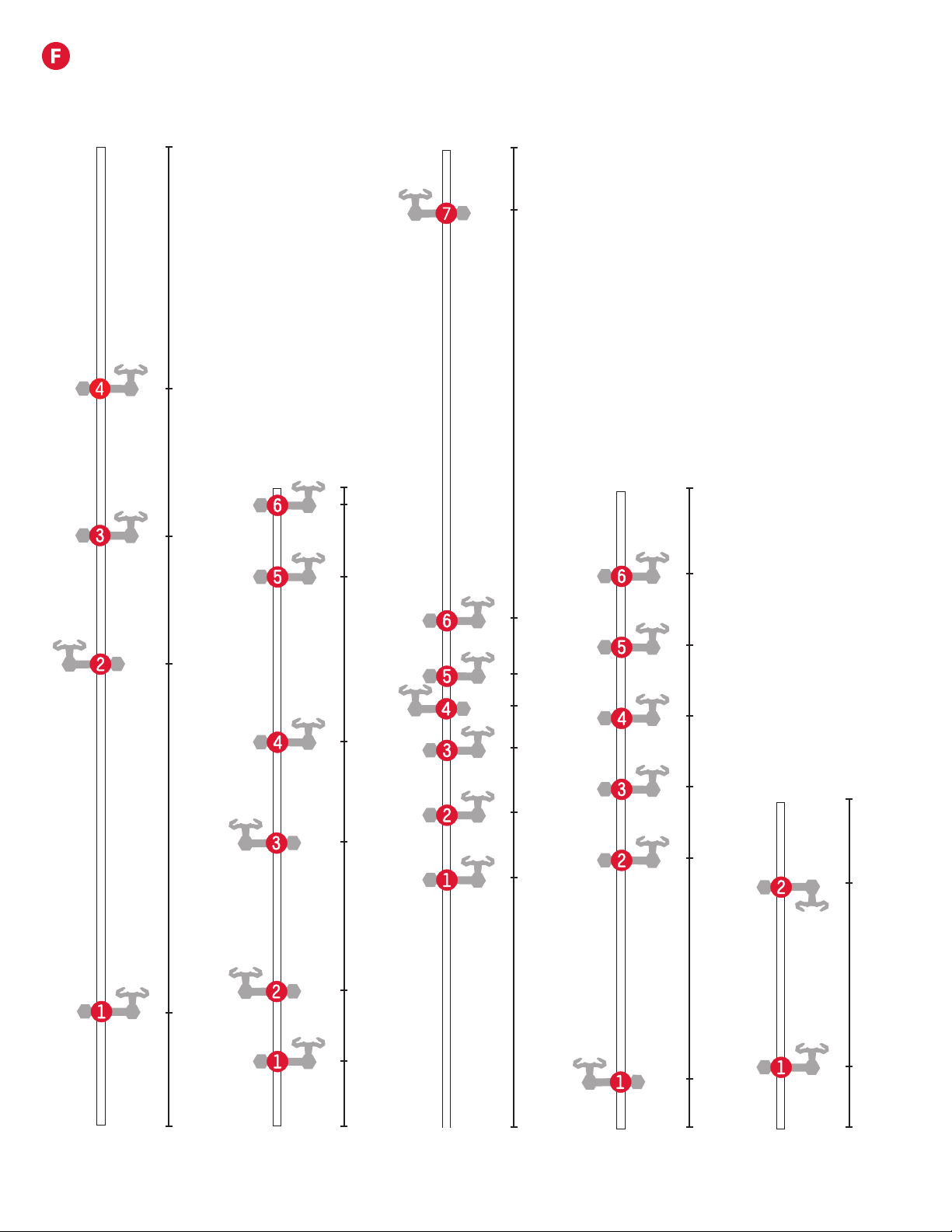
Step 2: Attach each arm as shown in step 1 with the orientation and location shown here. In later steps the letter of each
shaft and number of each arm will guide in the installation of the rails. For example arm A-3 below is 442 mm from the
base. Illustration is approximately 37% of actual size. All shaft measurements are in Millimeters.
391
49
65
98
140
160
183
223
254
Shaft E
Page 6 Seaich Corporation, LLC. All rights reserved. www.seaich.com |Spacerails, LLC. www.spacerails.com
Shaft I
391
28
163
206
250
293
337
Shaft J
200
37
148
SHAFT ASSEMBLY CONTINUED
600
151
191
230
256
270
310
560
Shaft H
600
281
448
360
68
379
391
335
234
173
82
38
Shaft F Shaft G

Seaich Corporation, LLC. All rights reserved. www.seaich.com |Spacerails, LLC. www.spacerails.com Page 7
Shaft K
300
35
83
214
254
Shaft L
300
235
TOP
BASE
BACK
OF BASE
FRONT
OF BASE
SHAFT TO BASE ORIENTATION
SHAFT ASSEMBLY CONTINUED
Shaft O
300
144
235
Shaft NShaft M
300
38
103
168
235
247
391
235
247
328

Page 8 Seaich Corporation, LLC. All rights reserved. www.seaich.com |Spacerails, LLC. www.spacerails.com
Shaft Q
Shaft T
153
Shaft R
589
180
330
475
519
Shaft S
43
90
125
160
195
230
253
300
Attach
arm L-1
Attach
arm M-4
43
76
111
147
182
217
253
Attach
arm O-2
Attach
arm P-3
300
Shaft S and shaft T are suspended above
the base using Arm B connections From
shafts L, M, O, and P.
Shaft P
300
105
187
235
SHAFT ASSEMBLY CONTINUED
TOP
BASE
BACK
OF BASE
FRONT
OF BASE
SHAFT TO BASE ORIENTATION

Seaich Corporation, LLC. All rights reserved. www.seaich.com |Spacerails, LLC. www.spacerails.com Page 9
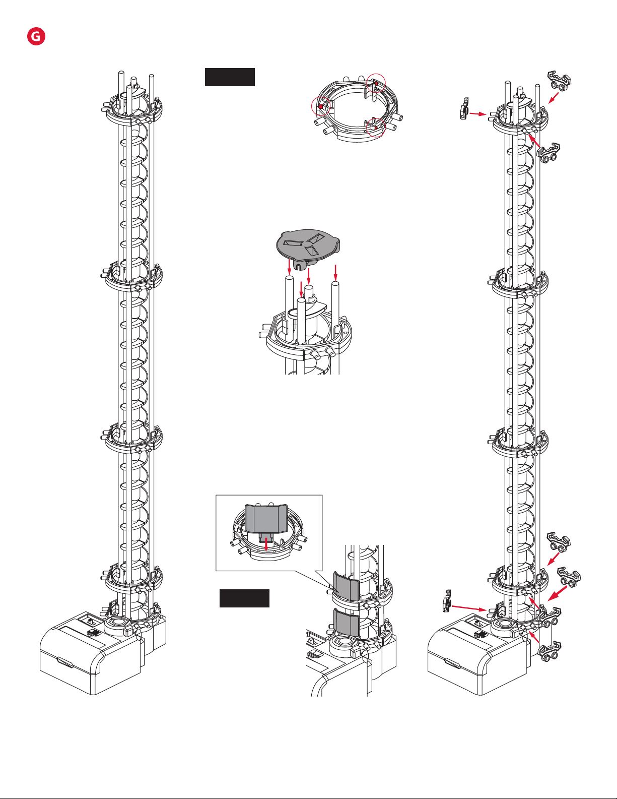
Step 3: Once the corkscrew is
built, attach three support shafts
to the Power Box.
Step 1: Place a 600 mm shaft in
the white hole on the Power Box.
ELEVATOR ASSEMBLY
Illustrations are approximately 33% of actual size.
Step 2: Connect Elevator Helix
pieces together with the male part
facing up to ll the shaft.
NOTE:
Install the rst
Elevator Helix
piece male side up
and rotate it until
it slides in place
and engages with
driver at the base
of Power Box.
Page 10 Seaich Corporation, LLC. All rights reserved. www.seaich.com |Spacerails, LLC. www.spacerails.com
NOTE:
The Marble may
fall out of the
elevator if it
enters too fast.
Step 7: Attach Rail Clips to each
Elevator Ring as shown.
Step 4: Slide each Elevator Ring
into position on the support
shafts right-side up.
Step 6: Insert three Elevator Guards each in
the bottom two Elevator Rings.
Step 5: Place the Elevator Cover onto the
top of the elevator assembly.
NOTE:
Elevator Rings are
right side up when
tabs in red are
on the top.
550 mm
385 mm
200 mm
30 mm
0 mm
ELEVATOR ASSEMBLY CONTINUED

Seaich Corporation, LLC. All rights reserved. www.seaich.com |Spacerails, LLC. www.spacerails.com Page 11
CUT THE RAIL TO SIZE
15 cm
a
b
22 cm
c
28 cm
d
78 cm
e
90 cm
f
150 cm
g
310 cm
h
360 cm
i
365 cm
j
435 cm
Step 1: Measure each section and mark the cutting point with a pen. Rail measurements
are in Centimeters.
Step 2: Cut each section according to your measurement. Make sure to cut at a 90° angle.
Tip: To help avoid do-overs and using too much rail, cut generously (slightly longer than
required) to begin with. You can always cut a long rail shorter.
NOTES:
Illustration of rail lengths is 4% of actual size.
Please see the included full size drawings. This will simplify the
positioning of base, arms, shafts, and the rail cut lengths.
H
Page 12 Seaich Corporation, LLC. All rights reserved. www.seaich.com |Spacerails, LLC. www.spacerails.com
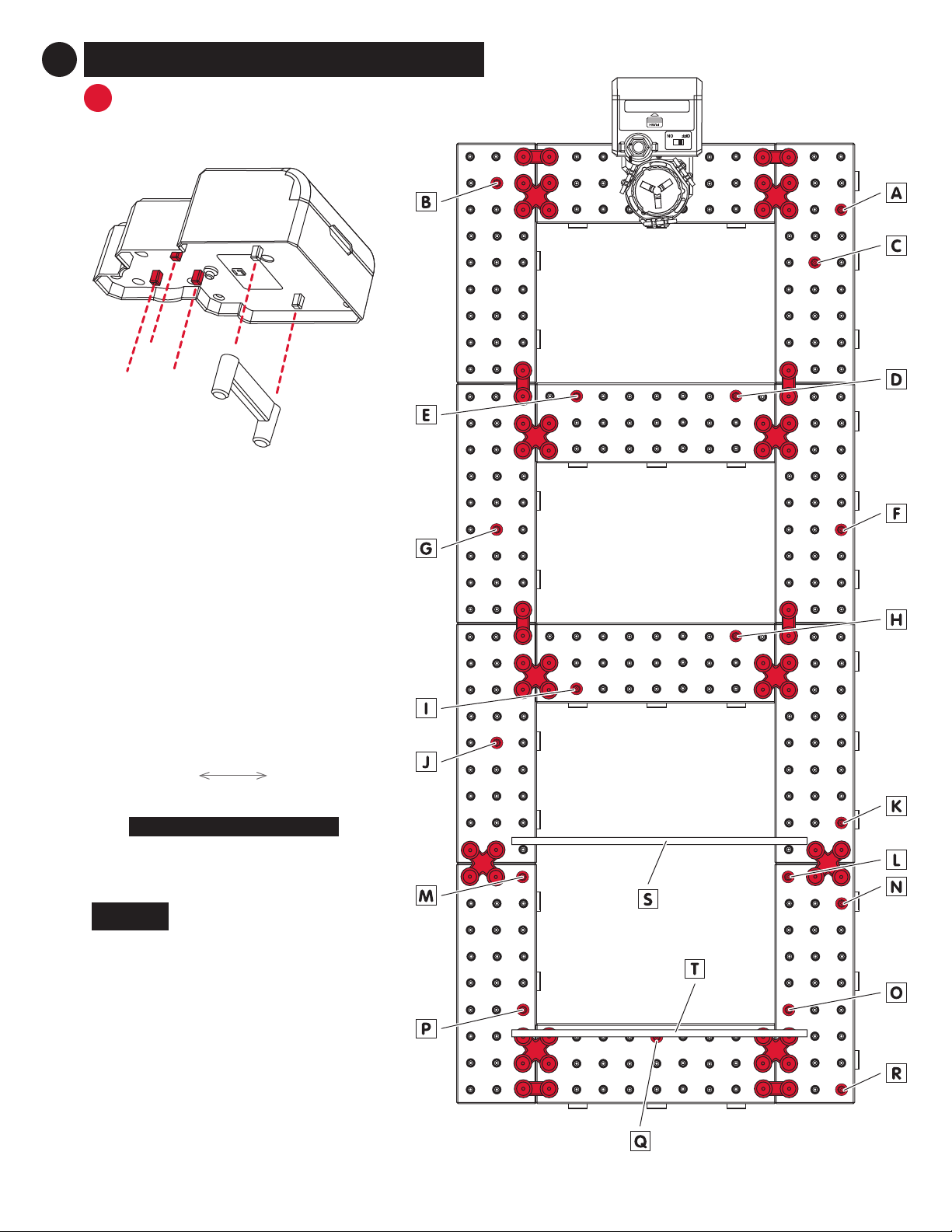
INSTALL ELEVATOR AND SHAFTS TO BASE
Illustrations are approximately 28% of actual size.
Step 1: Attach Power Box Stand to the
Power Box.
Step 2: Firmly seat the posts from the
Power Box in the holes on the base.
Step 3: Use diagram on the left for
location of each shaft. Push shaft into
holes on base until sturdy. Refer to
drawings on pages 5 through 7 for
orientation to install shafts.
FRONT
OF BASE
BACK
OF BASE
Posts attach
to base
2CONSTRUCTING THE ROLLER COASTER
A
NOTE:
Shaft S and shaft T are suspended above
the base using Arm B connections from
shafts L, M, O, and P.
BACK
OF BASE
FRONT
OF BASE
SHAFT TO BASE ORIENTATION

Seaich Corporation, LLC. All rights reserved. www.seaich.com |Spacerails, LLC. www.spacerails.com Page 13
BINSTALLING RAILS
Connecting rails to arms: To install the rails, press them into the arm as
shown. You should hear a click when the rail is locked in place.
When building a curved Rail Clips and Arm Clips
can be adjusted to create a banked curve. Plenty
of Rail Clips are included so that they can be
applied liberally.
Attach Rail Clips every 8-10 cm along rail
to maintain stability and keep rails parallel.
Keeping rails uniform maintains speed and
avoids throwing the Marble o course.
Rails should extend into the elevator
enough to catch the Marble.
Rail Couplings are provided but not needed. If
more length is needed for a rail, insert the coupling
into the end of both rails being joined.
Keep incline as smooth as possible to avoid
losing speed or contact with rails.

Page 14 Seaich Corporation, LLC. All rights reserved. www.seaich.com |Spacerails, LLC. www.spacerails.com
BINSTALLING RAIL
Rail Section 1:
Step1: Install one side of a rail at a time. Starting at the
top center Elevator Ring connect rail D (78 cm) to rail
Clip. Keeping rail tight connect to arm H-7 and Finish rail
at arm R-4. Repeat step for second rail. Attach Rail Clips
every 8-10 cm along rail to maintain stability and keep
rails parallel.
Step2: Starting at arm R-5 connect rail E (90 cm). Loop
rail under and connect to arm R-3. Keeping rail tight
connect to arm F-4 and Finish rail at arm A-3. Repeat step
for second rail. Attach rail Clips every 8-10 cm along rail
to maintain stability and keep rails parallel.
Step 3: Starting at arm A-4 connect rail B (22 cm). Loop
rail under and connect to arm A-2. Finish by attaching
the rail to the Rail Clip on single side of the Rail Splitter.
Fine Tune: Once each rail section is completed run a
Marble down your course and make sure it travels well.
Make any adjustments as needed. Do not worry about
adjusting the splitter until all rails have been connected.

Seaich Corporation, LLC. All rights reserved. www.seaich.com |Spacerails, LLC. www.spacerails.com Page 15
Step1: Start by attaching rail A (15 cm) to Rail Clip of rst
splitter facing the front of the base. Connect rail through
arm D-3 and nish by attaching rail to the Rail Clip on
the single side of the second Rail Splitter. Repeat step for
second rail.
Step2: Connect rail G (310 cm) to Rail Clip on second
splitter facing the back of the base. Create an nested loop
where each successive loop is slightly smaller than the
one above it. Starting with the inside rail connect arms
I-6, H-6, I-5, H-4, I-4, H-3, I-3, H-2, I-2, H-1, across to arm
E-4 and arm B-2. Finish at Rail Clip on Elevator Ring 2
facing the front of the base. Repeat step for the outside
rail. At least one rail will need to be trimmed at Elevator
Ring. Attach Rail Clips to keep rails consistently spaced,
supported, and create banked corners as needed.
BINSTALLING RAIL
Rail Section 2:
NOTE:
If length of rail is longer or shorter than
expected try adjusting the size of the nested
loops to better utilize the rails.
This top view of the nested loop section shows how each successive loop
is slightly smaller than the one above it. Start with a loop of about 20 cm
and work down to about 17 cm on the bottom loop. These numbers are
intended to be a guide only. Test your loops with the Marble. Adjust until
you get good consistent speed throughout this section.
Page 16 Seaich Corporation, LLC. All rights reserved. www.seaich.com |Spacerails, LLC. www.spacerails.com
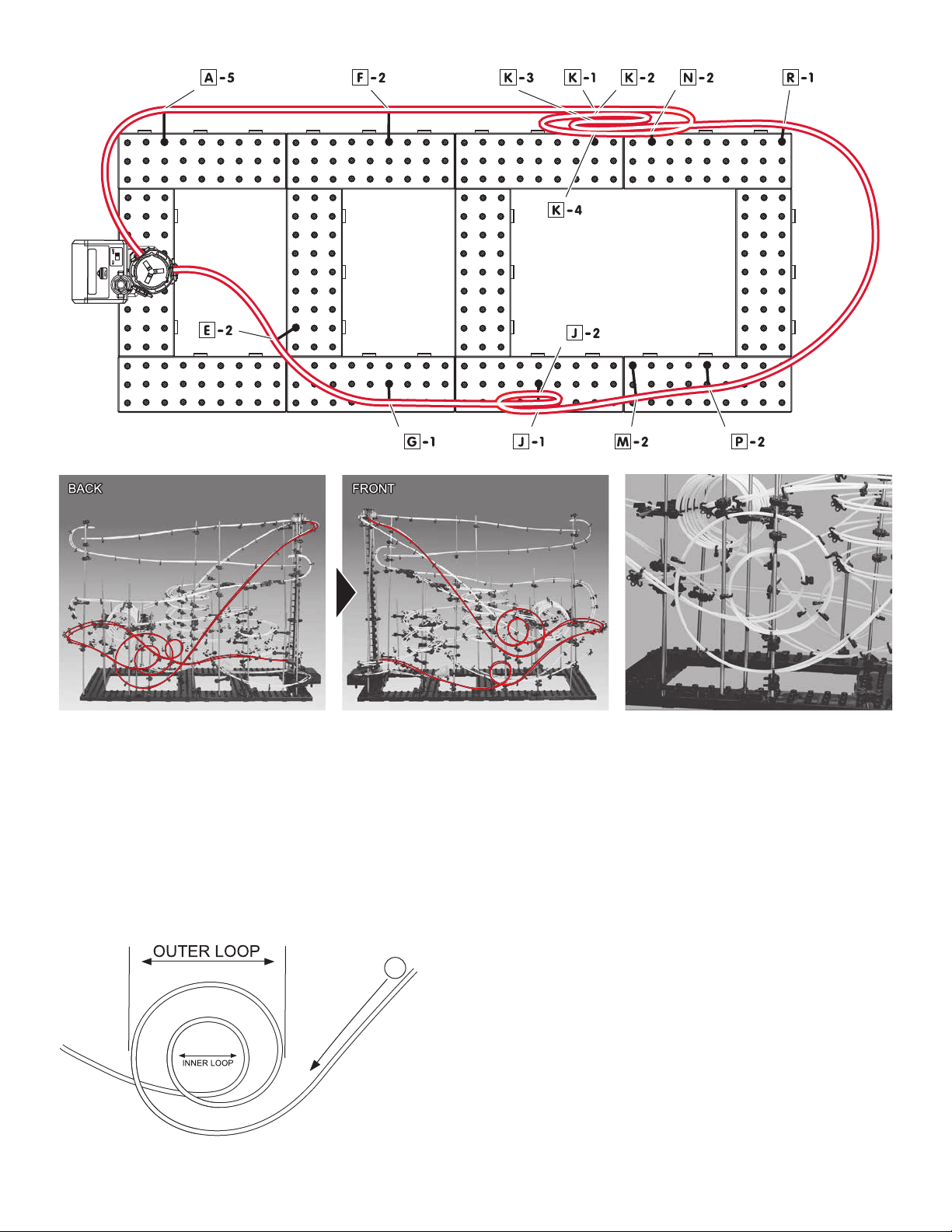
Rail Section 3:
Step1: Starting at the top Elevator Ring facing the back
of the base connect rail H (360 cm) to inner side of Rail
Clip. Keeping rail tight connect to arm A-5 then arm F-2
and K-1. Loop rail up to arm N-2 and K-4. Loop down to
K-2 and up to K-3 to create the inner loop. The inner loop
will shift inside the outer loop and pass right next to
shaft K and shaft N.
Step2: Create a banked rail through arm R-1 and arm
P-2. Continue rail through arm M-2 and arm J-1. Loop up
to arm J-2 and shift loop inside and up through arm G-1.
Finish by passing through arm E-2 and into the Rail Clip
on the bottom Elevator Ring in the center position.
Step3: Repeat Step 1 and Step 2 for the outer rail. Attach
Rail Clips to keep rails consistently spaced, supported,
and create a banked corner as needed.
For the double loop a good starting point for size is 20
cm for the outer loop and 10 cm for the inner loop.
For the single loop on the front try starting with a
10cmloop.
These numbers are intended to be a guide only. Test
your loops with the Marble. Adjust until you get good
consistent speed throughout this section.

Seaich Corporation, LLC. All rights reserved. www.seaich.com |Spacerails, LLC. www.spacerails.com Page 17
Rail Section 4:
Step1: Starting at the top Elevator Ring facing the front
of the base connect rail J (435 cm) to inner side of Rail
Clip. Keeping rail tight connect to arm B-3 then arm
G-6 and M-3. Loop rail up to arm T-1 and down through
S-1. Create a nested loop where each successive loop is
slightly smaller than the one before it by looping through
arms T-2, S-2, T-3, S-3, T-4, S-4, T-5, S-5.
Step2: Create a banked rail through arm O-1 and arm
P-1. Continue rail through arm G-2, arm F-1, and arm A-1.
Finish at Rail Clip on Elevator Ring 1 facing the back of the
base.
Step3: Repeat Step 1 and Step 2 for the outer rail. Attach
Rail Clips to keep rails consistently spaced, supported,
and create a banked corner as needed.
NOTE:
This image shows a close up
of the horizontal loops and
how rail Section 6 will pass
through them.
NOTE:
Start with a loop of about 13 cm on the front and work
down to about 9 cm on the back loop. These numbers
are intended to be a guide only. Test your loops with
the Marble. Adjust until you get good consistent speed
throughout this section.

Page 18 Seaich Corporation, LLC. All rights reserved. www.seaich.com |Spacerails, LLC. www.spacerails.com
Rail Section 5:
Step1: Start by attaching rail F (150 cm) to Rail Clip of
rst splitter facing the back of the base. Connect rail
through arms F-3, N-3, R-2, Q1, M-1, and I-1 creating a
ramp to jump the Marble. Repeat step for second rail. Do
not trim excess rail until the ramp has been ne tuned.
Adjust the speed and angle of the ramp for the jump and
catch to be successful.
Step2: Attach rail C (28 cm) to arm E-1 and nish at the
Rail Clip on Elevator Ring 2 in the center position.
Step3: Attach the Capsule Ring and Capsule to rail C as
shown below.
Arm E-1 Arm E-1 Rail Clip

Seaich Corporation, LLC. All rights reserved. www.seaich.com |Spacerails, LLC. www.spacerails.com Page 19
Rail Section 6:
Step1: Start by attaching rail I (365 cm) to the inside
Rail Clip of second splitter facing the front of the base.
Connect rail through arms G-5 and arm M-5. Pass rail
through horizontal loop section and attach arm N-1 and
then arm H-4.
Step2: Pass rail I between shaft D and shaft E and attach
to arm E-8. To create the Figure 8 section the arms on
shaft D and shaft E will need to be rotated around the
shaft. Continue creating the gure 8 section with arms
G-4, E-7, C-2, D-2, E-6, G-3, E-5, C-1, and E-3. Finish by
passing through arm B-1 and into the Rail Clip on the
bottom Elevator Ring facing the front of the base.
Step3: Repeat Step 1 and Step 2 for the outer rail. Attach
Rail Clips to keep rails consistently spaced, supported,
and create a banked corners as needed.
NOTE:
Congratulations on completing Spacerails Level 8! Fine
tune the rails and see how many marbles you can get
going at the same time. If the marbles are coming into
the elevator too quickly it may knock other marbles
already in the tower out. Create a dip or nd other ways
to slow marbles to just the right speed at entrance.

Seaich Corporation
1910 West 1040 South
Salt Lake City, UT 84104
(833) 732-4242
Spacerails LLC
Spacerail © 2021
www.spacerails.com
Table of contents
Other Spacerails Toy manuals

Spacerails
Spacerails Level 3 User manual

Spacerails
Spacerails Level 7 User manual

Spacerails
Spacerails Level 1 User manual

Spacerails
Spacerails Level 2 User manual

Spacerails
Spacerails Level 5 User manual

Spacerails
Spacerails LEVEL 6 User manual

Spacerails
Spacerails LEVEL 4 User manual

Spacerails
Spacerails Level 9 User manual


 ABRAMS Assembly manual")


