Spacerails LEVEL 4 User manual

LEVEL 4
PRODUCT AND CONSUMER WARNING
CHOKING HAZARD: This product contains small parts and is not intended for children under 3.
• This product is intended for users 8 years of age and older.
• To avoid choking, keep small parts away from children.
• Use caution—this product contains parts with sharp edges.
• To avoid potential damage to the product, only insert the included marbles into the elevator.

Page 2 Seaich Corporation, LLC. All rights reserved. www.seaich.com |Spacerails, LLC. www.spacerails.com
PARTS INCLUDED
Keep parts together to avoid misplacing them.
ARM COMPONENTS
Arm Clip
x56
Arm Sheath
x60
Arm Holder A
x56
Arm Holder B
x62
Arm Lock
x118
RAIL COMPONENTS
Rail Coupling
x10
Marble
x4
Rail
26,000 mm
REQUIRED TOOLS & ITEMS (NOT INCLUDED)
Wire Cutters or Utility Scissors
Pen or Marker
3 AA Batteries (newer models) or 1 C Battery
Ruler (in centimeters)
Rail Clip
x70
SPLIT, SEE-SAW, AND START BLOCK COMPONENTSBASE COMPONENTS
Base Base Holder A Base Holder B
x9 x4 x6
Rail Splitter
x1
Start Block
x1
Start Block
Cover
x1
See-Saw Arm
x3
ELEVATOR COMPONENTS
Elevator Helix
x12
Elevator Ring
x3
Elevator Cover
x1
Elevator Guard
x4
Power Box Stand
x1
Power Box
x1
Shaft (300mm)
x16
Shaft (200mm)
x5
Shaft Connector (90mm)
x1
Shaft Connector (50mm)
x1

Seaich Corporation, LLC. All rights reserved. www.seaich.com |Spacerails, LLC. www.spacerails.com Page 3
A
B
ARM ASSEMBLY (QTY: 66 SHAFT TO RAIL)
RAIL SPLITTERS
1PREPARE THE COASTER COMPONENTS
Step 1: Attach one Arm Holder A and one
Arm Holder B with one Arm Sheath.
Step 2: Insert one Arm Clip into Arm
Holder A. Slide the circular part between
the matching parts on the Arm Holder.
Step 1: Attach one Rail Clip on each of
the Rail Splitter posts.
Step 4: Turn the Arm Lock
counter-clockwise to secure the
ArmClip in place.
Step 3: Insert Arm Lock through Arm
Holder A and Arm Clip. Ensure that the
tab is facing up.
To avoid damaging parts, do not move or adjust the Rail Clip while locked in the arm. To move the Rail Clip, release
Arm Lock by turning clockwise, position Rail Clip as desired, then secure Arm Lock again.
NOTE:
The hole shapes of the Arm Holder
and Arm Sheath dier.
Arm Holder B Arm Holder A

Page 4 Seaich Corporation, LLC. All rights reserved. www.seaich.com |Spacerails, LLC. www.spacerails.com
C
D
SEE-SAW ASSEMBLY
BASE ASSEMBLY
Step 1: Cut 2 rails to 55mm. Insert 1 rail into
each hole on the See-Saw.
Step 2: Insert the See-Saw Arm and the rails into
the Rail Clip. You may need to adjust the See-Saw
after installing it as it may have shifted.
Step 3: Insert See-Saw into Arm Holder B. Step 4: Insert the See-Saw into the Rail Stand
(300mm Shaft). See shaft assembly on page8
for exact placement.
See-Saw Arm
Rail Clip
55mm rail pieces
Step 1: Interlock Base block tabs
as shown below.
Step 2: Press Base Holder A and
Base Holder B pieces into the Base
blocks for a more secure hold.
1
2
2
NOTE:
Base Holder B is used
here instead of A.
Seaich Corporation, LLC. All rights reserved. www.seaich.com |Spacerails, LLC. www.spacerails.com Page 5
Step 3: Once the Corkscrew is
built, attach three support shafts
(300mm) to the Power Box.
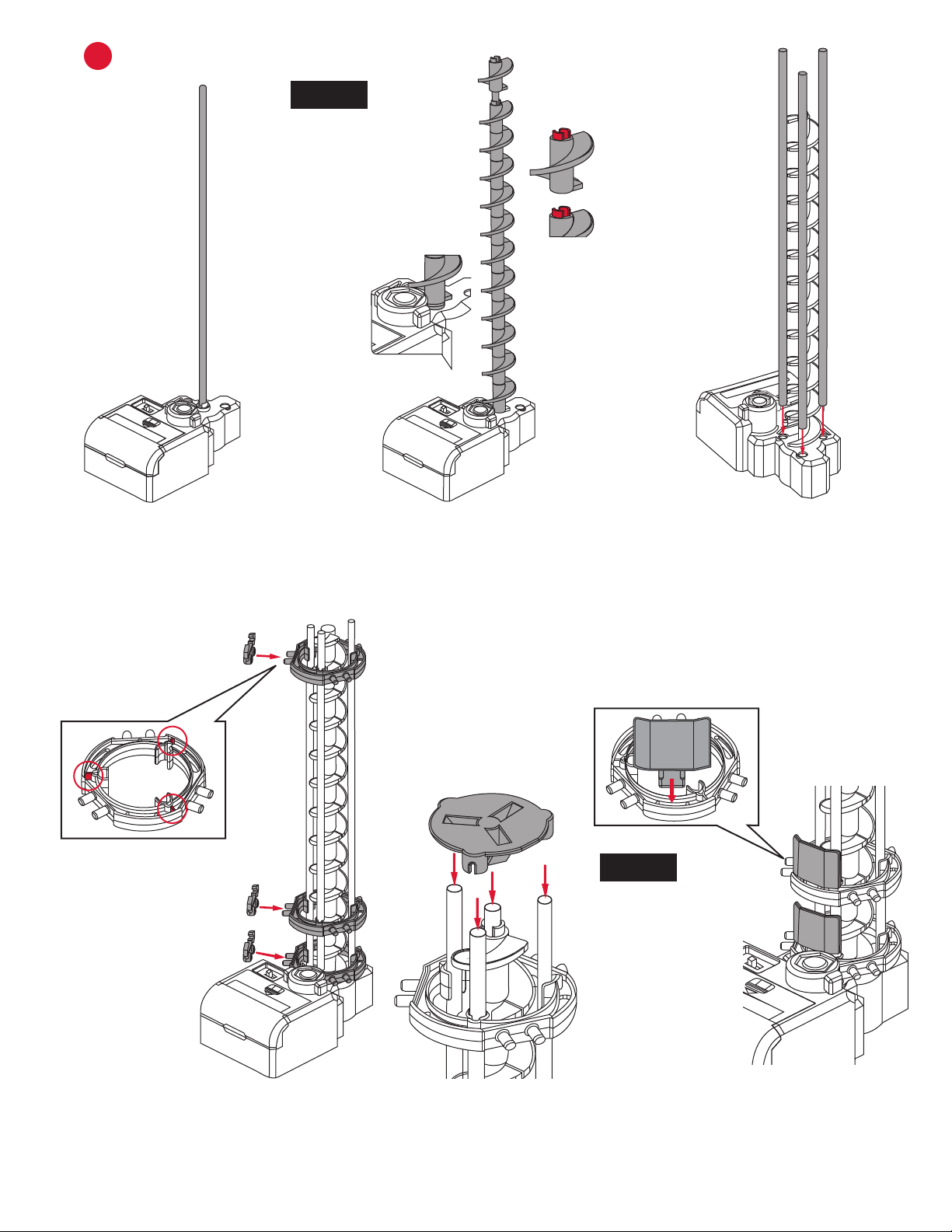
EELEVATOR ASSEMBLY
Step 2: Connect Elevator Helix
pieces together with the male part
facing up to ll the shaft.
NOTE:
Install the rst Elevator
Helix piece male side
up and rotate it until
it slides in place and
engages with driver at
the base of Power Box.
Step 1: Place a shaft in the
white hole on the Power Box.
Step 6: Place the Elevator Cover
onto the top of the elevator
assembly.
Step 7: Attach an Elevator Guard to
each of the Elevator Rings, then to
the right side of the Rail Clip.
Step 5: Place the three Elevator
Rings over the three shafts.
NOTE:
The Marble may fall
out of the elevator if it
enters too fast.
Step 4: Connect
one Rail Clip to each
Elevator Ring. Install
Elevator Ring with
tabs facing up, as
shown above.

Page 6 Seaich Corporation, LLC. All rights reserved. www.seaich.com |Spacerails, LLC. www.spacerails.com
F
G
STARTER ASSEMBLY
SHAFT ASSEMBLY
Step 1: Connect Arm Holder B to
300mm Shaft. Insert Arm Lock.
Step 4: Attach Rail Clips and
Start Block Cover to Starter.
Step 1: Slide Arm Holder B of each arm on
to a shaft and lock in place with Arm Lock.
Refer to the next page for orientation and
location of each arm.
This is how the pieces are
referenced on the shaft drawings.
Arm
Arm Holder B
See-Saw
Step 2: Connect the Starter pegs
to the Arm Holder.
Step 3: Ensure the Starter is at
a slight angle so the Marble will
run smoothly.
NOTE:
Please see the included full-size drawings for the next
several steps. This will simplify the positioning of base,
arms, shafts, and the rail cut lengths.
Seaich Corporation, LLC. All rights reserved. www.seaich.com |Spacerails, LLC. www.spacerails.com Page 7
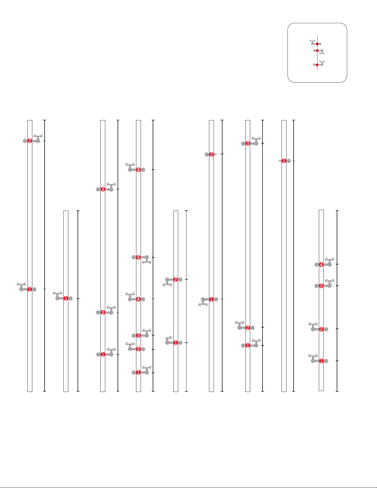
Step 2: Attach each Arm and See-Saw Arm as shown in step 1 with the orientation
and location shown here. In later steps the letter of each Shaft and number of each
Arm will guide in the installation of the Rails. Illustration is approximately 51% of
actual size. All Shaft measurements are in Millimeters.
200 200 200
104
124
140
117
68
54
33
300
41
225
88
300
149
103
62
47
21
247
300
102
264
300
71
51
276
300
256
300
113
278

Page 8 Seaich Corporation, LLC. All rights reserved. www.seaich.com |Spacerails, LLC. www.spacerails.com
Step 2 Continued
300 300 300 300 300300
110
67 72
24
55
79 80
111
123
119
78
107
135
162
199
115
161
168
216
201 203
240
208
226
216
258
241
277 283
281
200 200
109
60
99
141
185

Seaich Corporation, LLC. All rights reserved. www.seaich.com |Spacerails, LLC. www.spacerails.com Page 9
HINSTALLING SHAFTS INTO BASE
Start Block
Shaft Stand
Shaft Stand
LEFT
RIGHT
FRONTBACK
Step 3: Place shafts and elevator into base.
Push shaft into holes on base until sturdy.
Attach Power Box Stand to the Power Box.
Firmly seat the posts from the Power Box in
the holes on the base.
Step 4: Attach Shaft Connector (90mm) to
Shafts K and N. Attach Shaft Connector (50mm)
to Shafts F and G.
Page 10 Seaich Corporation, LLC. All rights reserved. www.seaich.com |Spacerails, LLC. www.spacerails.com
CUT THE RAIL TO SIZE
Step 1: Measure each section and mark the cutting point with a pen.
Step 2: Cut each section according to your measurement. Make sure
to cut at a 90° angle.
Tip: To help avoid do-overs and using too much rail, cut generously
(slightly longer than required) to begin with. You can always cut a
long rail shorter.
NOTES:
Illustration of rail lengths is
approximately 5% in scale.
Measure carefully and use a tape
measure for longer segments.
See included insert for rail
measurements in 1:1 scale.
G
300cm
A
5cm
B
45cm
45cm
C
200cm
200cm
D
E
F
G
350cm
Seaich Corporation, LLC. All rights reserved. www.seaich.com |Spacerails, LLC. www.spacerails.com Page 11
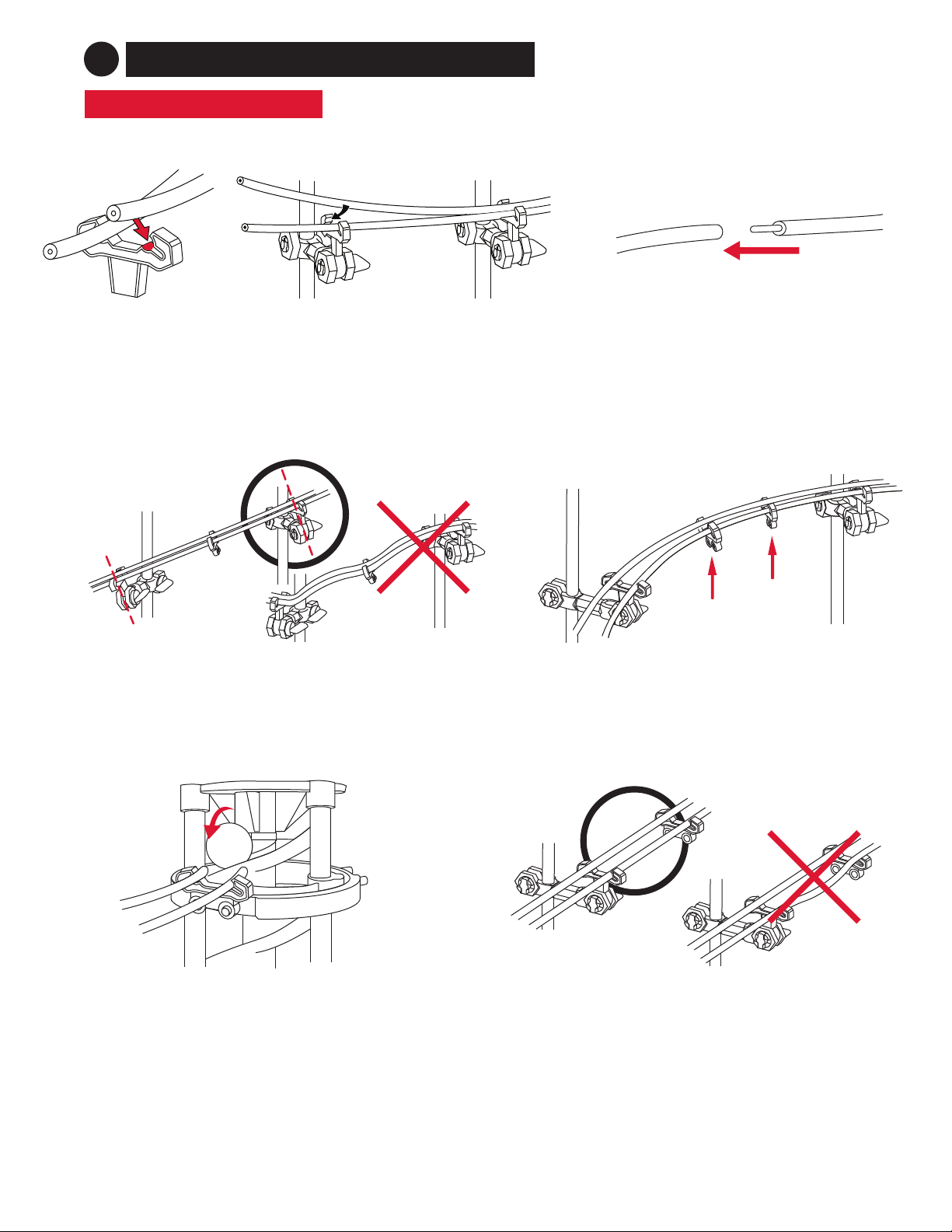
Rail joining for custom designs: To adjust your
designs with the rails, use the Rail Couplings to
increase the length of your rail sections.
Connecting rails to arms: To install the rails, press them
into the arm as shown. You should hear a click when the
rail is locked in place.
Angling the arms: Install the arms at the angle of the
incline the rails will travel along.
Railroad stability: To maintain stability on longer
track segments, attach Rail Clips as needed.
Elevator Exit: When installing the elevator exit rails,
pull the rails close to the Elevator Helix to ensure the
Marble enters the roller coaster smoothly.
Smooth rails for ecient travel: Make sure the
rails connect smoothly and are free of any bumps,
twists, or kinks.
ASSEMBLY TIPS & TRICKS
2CONSTRUCTING THE ROLLER COASTER
Page 12 Seaich Corporation, LLC. All rights reserved. www.seaich.com |Spacerails, LLC. www.spacerails.com
Use the following illustrations and pictures as references for attaching the rails to the structure:
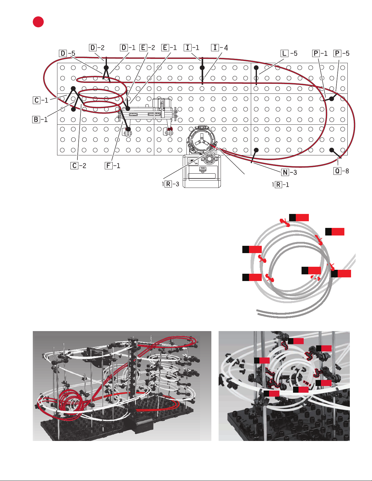
INSTALL RAIL A
A
Step 1: Install one side of a rail at a time. Starting at the top right Elevator
Ring (1R-1) connect Rail A (300 cm) to Rail Clip. Curving rail, connect to
Arm P-1. Continue the curve and connect to Arm I-1 then, keeping rail
tight, connect to Arm D-1. Curve rail and connect to C-1. Attach Rail Clips
every 8-10 cm along rail to maintain stability and keep rails parallel.
Step 2: Begin the Loop. You will need to angle arms and Arm Clips to
create loop as shown below. Starting at Arm F-1 loop rail and attach at
C-2 then E-2 to create a circular shape. Continue with B-1, E-1, D-5, then
D-2. You should now have 3 complete loops.
Step 3: Keeping rail tight, connect to I-4, then L-5. Curve rail and attach
to P-5, Q-8, N-3, and then nish at Elevator Exit (R-3).
Fine Tune: Once each rail Section is completed run a Marble down your
course and make sure it travels well. Make any adjustments as needed.
The Loop will need to be adjusted and the rail angles tweaked.
D-56
F-1
1
C-2
2E-1
5
B-1
4
E-2
3
D-5
B-1
F-1
E-1
E-2
C-2
6
1
3
2
5
4
D-5
B-1
F-1
E-1
E-2
C-2
6
1
3
2
5
4
Rail A Loop
Elevator Exit Elevator Entry

Seaich Corporation, LLC. All rights reserved. www.seaich.com |Spacerails, LLC. www.spacerails.com Page 13
INSTALL RAILS B, C, AND DB
Step1: Starting at the top center Elevator Ring (2R-1) connect Rail B (5 cm) to Rail Clip. Connect the other
end to the Rail Splitter. The Rail Splitter will not be held up by a shaft.
Step2: Connect Rail C (45 cm) to the right side of the Rail Splitter. Curve the rail and Connect to L-6, then
O-6, then P-4. Rail will end above the two See-Saws. You can use a Marble to adjust the See-Saws. The
Marble should fall onto each See-Saw Arm and tip the See-Saw forward, falling onto the one beneath it.
Step 3: Connect Rail D (200 cm) to the left part of the Rail Splitter. Continue rail to D-6 and curve around
to connect to C-3. Continue in a downward slope to J-1, then loop rail and attach to K-2 then K-1.
Step 4: Continue rail in a curve and attach to L-4, then I-3. Curve rail the opposite way and connect to
G-2, under the Start Block, and nish at Elevator Exit R-3.
Rail B, C, and D See-Saws
Seesaw
Elevator Exit
Elevator Entry

Page 14 Seaich Corporation, LLC. All rights reserved. www.seaich.com |Spacerails, LLC. www.spacerails.com
INSTALL RAIL EC
Step 1: Starting at the middle center Elevator Ring (3R-2) connect Rail E (200 cm) to Rail Clip. Continue rail
between Shaft I and J. Curve to connect to Arm L-2, then N-1. Line rail around the outside of the structure to
A-1 then D-4, L-3, and P-2. Rail ends above See-Saw Arm.
Rail E
Rail F and G
Elevator Entry

Seaich Corporation, LLC. All rights reserved. www.seaich.com |Spacerails, LLC. www.spacerails.com Page 15
INSTALLING RAIL F AND G
D
Step 1: Starting at the top left Elevator Entry 3(R-3) connect Rail F (45 cm) to Rail Clip. Curving rail, connect to
Arm G-1 then Arm A-2. Continue the curve and connect to Start Part.
Step 2: Starting at The bottom left Elevator Entry 3(R-3), connect Rail G (350 cm) to Rail Clip. Curve rail and
connect to G-3, then through the triple loop to D-3. Keeping rail tight, connect to I-2, then L-1 and O-1. Curve
rail and attach to Q-1.
Step 3: You will now begin the spiral. You may have to adjust the angle of the arms and Rail Clips. Connect rail
to Arm M-1, then curve the rail tightly to O-2 then Q-2. Continue spiral upward to M-2, O-3, Q-3, M-3, O-4, and
Q-4. Finish the top of the spiral with M-4, O-5, and Q-6. Then bring rail out and connect to Arm N-2 and then
back to the Start Block.
NOTE:
You may want to start with the majority of the rail towards the back of the base. Then, you can put a
small portion of the end of the rail through the triple loop and connect back to the elevator piece.
When constructing the spiral on the right of the structure, you will need to guide the excess rail to
more easily attach rail to Rail Clips.
Fine Tune: Once each rail section is completed
run a marble down your course and make sure
it travels well. Make any adjustments as needed.
The spiral will need to be adjusted and the rail
anglestweaked.
Elevator Exit
Elevator Entry

Seaich Corporation
1910 West 1040 South
Salt Lake City, UT 84104
(833) 732-4242
Spacerails LLC
www.spacerails.com
Table of contents
Other Spacerails Toy manuals

Spacerails
Spacerails Level 1 User manual

Spacerails
Spacerails Level 5 User manual

Spacerails
Spacerails LEVEL 6 User manual

Spacerails
Spacerails Level 8 User manual

Spacerails
Spacerails Level 9 User manual

Spacerails
Spacerails Level 7 User manual

Spacerails
Spacerails Level 2 User manual

Spacerails
Spacerails Level 3 User manual
Popular Toy manuals by other brands

MTHTrains
MTHTrains Premier SD50 Diesel Engine Operator's manual

Fisher-Price
Fisher-Price Miracles & Milestones K4067 quick start guide

REVELL
REVELL B-24D Liberator Assembly manual

REVELL
REVELL Supermarine Spitfire IXC/XVI Assembly manual

Elenco Electronics
Elenco Electronics SNAP CIRCUITS XP SCXP-50 instruction manual

Nerf
Nerf Rival KRONOS XVIII-500 instructions


