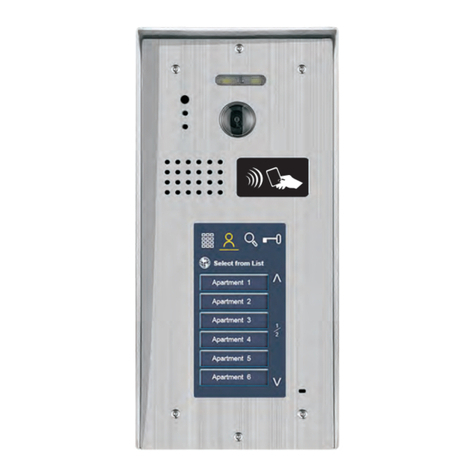
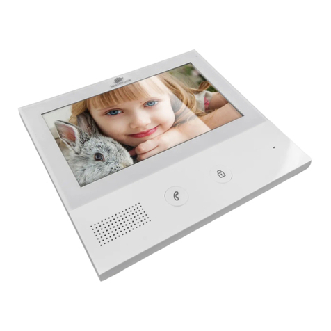
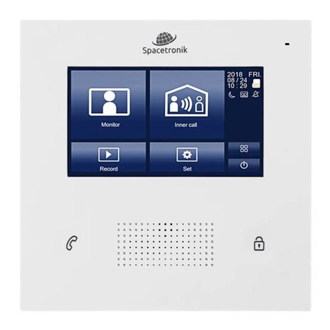
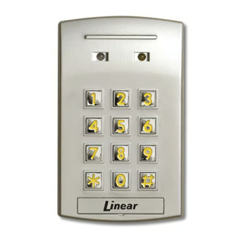
Spacetronik DIO SPD-DS81 Series User manual

Door Station
SPD-DS81x
User’s Manual
Please read this manual carefully before using the product .

1. Parts and Functions
Connection Port
BUS CAM LOCK
ON DIP
182mm (13.7in)
110mm (4.3in) 55mm (2.1in)
Speaker
LED
ID Card Window
Name plate
Call button
Microphone
Light-sensing touch button: When any object blocks the
button, the button can be triggered. (Which solved the problem
that the capacitive touch button cannot trigger the button when
people wear gloves.)
Alex
Press down and move left to open the transparent nameplate cover.
Then insert the name paper and put the cover back.
-1-

2. Terminal Description
Connection Port
BUS
L1 L2
CAM LOCK
VI- VI+ NO NC COM GND GND OPEN
SIP1
ON DIP
.
CAM: Extra camera connection port.
LOCK: Electronic lock connection port.
VOL: Volume adjustor.
DIP : DIP switches for system configurations.
SIP1: Door lock jumper.
NPC: DIP switch, bits1/ 2/ 3 are used for NFC command
selection. Long press the switch for 2 seconds to set.
100: Make a master card.
000: Use IC card encryption mode (password fixed).
111: Use IC card without encryption mode.
010: Delete a IC card or key tag.
001: Format all the IC cards or key tags.
BUS: (L1, L2) non-polarity bus line
2222222
NFC
Swipe the IC card to open the door
Swipe a user card to hear a long beep, the door opens. Swipe
a non-user card to hear a short ring three times, the door does
not open.
-2-

Make a master card
Set the DIP switch to 100, then long-press the switch for 2 seconds
to hear the beep sound every second, which enter the recording
management card mode, swipe a new IC card, and the master card
will be successfully make after a long beep sound
Delete a IC card or key tag
Set the DIP switch to 010, then long-press the switch for 2 seconds
to hear a beep sound. Swipe a user card or key tag to be cleared
within 10 seconds. If you hear three short beeps, the clearing is
successful.
Format all the IC cards or key tags
Set the DIP switch to 001, then press the switch for 2 seconds, and
then hear a beep sound to start formatting. After 5 seconds, you
will hear a beep sound again, all master cards and user cards are
cleared, and formatting is completed.
Add or delete a user card
Swipe the master card, will hear a beep every second, and swipe a
new user card within 60 seconds, hear a long beep again and enter
successfully ; then swipe an old user card, hear a short beep three
times, delete it successfully, and finally swipe the master card to
exit. It can support up to 2990 user cards.
Using IC card encryption mode (password fixed)
The DIP switch is set to 000. Press the DIP switch for 2 seconds
and then touch it lightly. After hearing a sound, the setting is
completed.Use IC card encryption mode, then when swiping a card
to unlock, IC card to have the corresponding password.This
function is used to prevent others from copying IC CARDS.
Use IC card without encryption mode
The DIP switch is set to 111. Press the DIP switch for 2 seconds
and then touch the switch. After hearing a sound, the setting is
completed.Use IC card not to encrypt mode, then when swiping a
card to unlock, as long as the corresponding IC card number can
unlock. After others can copy IC card by used copy card to unlock.
-3-

3. Mounting
4. System Connection
Single door station
1 2 3
1 2 3
Drill a hole and attach the rainy
cover to it
Attach the unit to the rainy cover
correctlly
The last view for all mounting
Router
-
+
Power supply
UTP5E
UTP5E
IP Module
Multi door station connection
N NC L
Input : 100-2 40V~
Power S upply
Model : 206A- 2S
Outpu t: 26V 2V M ax 7A
Bus(I M) Bus(DS)
Power S upply
+
-
/
N NC L
Input : 100-2 40V~
Power S upply
Model : 206A- 2S
Outpu t: 26V 2V M ax 7A
Bus(I M) Bus(DS)
Power S upply
+
-
/
-4-

A B CCCDDD
DIP
666555
ID=000
ON DIP
666111222333444555
ID=100
ON DIP
666111222333444555
ID=010
ON DIP
666111222333444555
ID=110
4
ON
111222333444
N NC L
Input : 100-2 40V~
Power S upply
Model : 206A- 2S
Outpu t: 26V 2V M ax 7A
Bus(I M) Bus(DS)
Power S upply
+
-
/
Multi Monitor Connection
Basic star Wiring
A B C D
OFF ON
A B C D
OFF ON
ON DIP
6 71 2 3 4 5
Code=24
ON DIP
6 71 2 3 4 5
Code=44
ON DIP
6 71 2 3 4 5
Code=14
ON DIP
6 71 2 3 4 5
Code=34
ON DIP
6 71 2 3 4 5
Code=10 4
ON DIP
6 71 2 3 4 5
Code=12 4
ON DIP
6 71 2 3 4 5
Code=9 4
ON DIP
6 71 2 3 4 5
Code=11 4
3
2
5
6
C
B
A
7
ON DIP
61 2 3 4 5
1
ID=000
When monitor quantity < 20
Cable Usage
2
Parallel cable 2x0.75mm
A
60
80
B
60
80
30
40
2
Parallel cable 2x1mm
C
When monitor quantity > 20
Cable Usage A
60
80
B
60
80
C
30
40
2
Parallel cable 2x1.5mm
2
Parallel cable 2x1mm
[1]: Door station, when there
is only one Door station, the
DIP bit-1, bit-2 and bit-3
should be set to 000.
[2]: Power supply, MUST be
installed side by side with
Power Separator.
[3]: Power Separator, MUST
be installed side by side with
Power supply.
[4]: Monitor, each one with an
unique User Code, note that
all the bit-6 of the DIP should
be set to 1(ON) in this case.
[5 ] : Vid e o d i s t ri b u t or se t
switch to OFF unless at the
end of the line.
[6 ] : Vid e o d i s t ri b u t or se t
switch to ON at the end of the
line.
[7]: Extra camera.
N NC L
Input: 100-240V~
Power S upply
Model: 206A-2S
Output: 26V 2V Max 7A
Bus(IM) Bus(DS)
Power S upply
+
-
/
-5-

5. DIP Switches Settings
Total 6 bits in the DIP switches can be configured. The switches can be
modified either before or after installation.
1 2 3 4 5 6
ON DIP
ON
ON
ON (1) OFF (0)
= =
6. Electric Lock Connection
12V 300mA
+
-
Jumper position in 2-3
NO NC COM G ND GN D OPEN
CN3
Exit button
12V 300mA
+
-
Jumper position in 1-2
NO NC COM G ND GN D OPEN
CN3
Exit button
Power ON to open Power OFF to unlock type
1 2 3
SIP1
1 2 3
SIP1
Electric control lock
Magetic lock
Bit-1,Bit-2 and Bit-3 are used for door station ID
setting(1=on,0=off).
Bit-1,Bit-2 and Bit-3 are used for door station ID
setting(1=on,0=off).
000 - 100 - 010 - 110 - 001 - 101 - 011 - 111
000 - First door station
100 - Second door station
010 - Third door station
110 - Fourth door station
Bit-4 and Bit-5 is used for unlock time setting.
00 - 1 second (Default setting)
10 - 5 seconds
01 - 10 seconds
11 - 15 seconds
Bit-6 is used for connecting extra camera.
0 - No extra camera (Default setting)
1 - Connecting with extra camera
1. The door lock power for a 12v DC strike (max current=250mA).
2. For Electric control lock, setting the jumper SIP1 to 2-3 for a normally
open lock (power ON to open);
For electromagnetic lock or magnetic lock,need set SIP1 to 1-2 for a
normally closed lock(power OFF to open)
3. Adjust the timer setting with Bit-4 and Bit-5 at the outdoor station
(1=on,0=off)
00-1sec, 01-5sec,10-10sec,11-15sec.
-6-

7. Electric Lock Connection
1. The external power supply must be used according to the lock.
2. The jumper must be taken off before connecting.
3. If different unlocking time is needed, change the unlock time on door
station by modifying the BIT-4 and BIT-5.
+
-
Take off the jumper
NO NC COM GND GND OPEN
CN3
1 2 3
SIP1
Exit button
-
+
+
-
Take off the jumper
NO NC COM GND GND OPEN
CN3
1 2 3
SIP1
Exit button
-
+
Power OFF to unlock type Power OFF to unlock type
Magetic lock
Magetic lock
Take off the jumper
12V 300mA
+
-
NO NC COM GND GND OPEN
CN3
Exit button
Power ON to open
1 2 3
SIP1
Electric control lock
+
-
-
+
8. Specification
Power Consumption: 1W in standby, 5W in working
Unlock Power output: 12Vdc, 250mA
Unlock timing: 1s, 5s, 10s, 15s
Working Temperature: -20℃~ +55℃
Power supply: DC 24V
The WEEE symbol (the crossed-out wheeled bin) using indicates that this product is not home waste. Appropriate
waste management aids in avoiding consequences which are harmful for people and environment and result from
dangerous materials used in the device, as well as improper storage and processing. Segregated household
waste collection aids recycle materials and components of which the device was made. In order to get detailed
information about recycling this product please contact your retailer or a local authority.
Produced in ChRL for: DMTrade Mikołaj Tomaszewski Wiśniowa 36; 64-000 Kościan, Poland
NIP: PL 6981681757 [email protected] Tel.: +48 697 222 052
This manual suits for next models
2
Table of contents
Other Spacetronik Intercom System manuals
