Spanco 100 Series Manual

Installation and Maintenance Manual for
SPANCO®(WC) Wall Cantilever Jib Cranes
Manual No. 103-0024
REV. 08/14
ISO 9001 REGISTERED
© SPANCO, Inc.

2

3
ABLE OF CON EN S
Forward...................................................................................................................... 4
Installation...............................................................................................................5-7
aintenance and Inspection......................................................................................8-9
Top & Bottom Bracket Assemblies: January 2011 and Earlier Only
WC 100, 150, 250, 500 & 1000 LBS..............................................................10-11
Top & Bottom Bracket Assemblies: January 2011 to June 2013
WC 100, 150, 250 & 500 LBS........................................................................12-13
Top & Bottom Bracket Assemblies: January 2011 to June 2013
WC 1000 LBS.................................................................................................14-15
Top & Bottom Bracket Assemblies: June 2013 and Later
WC 100, 150, 250, 500 & 1000 LBS..............................................................16-17
Bearing Assembly: Correct..........................................................................................18
Bearing Assembly: Incorrect...................................................................................19-22
Warranty and Service Policy........................................................................................24

4
This manual contains important information to help you install, operate, maintain, and
service your new jib crane. Please be sure to read this entire manual before installing or
operating your crane. We also recommend that you obtain the latest issue of ANSI B30.11
Safety Standard for Monorails and Underhung Cranes and study its contents thoroughly. By
practicing the recommended maintenance suggestions, with proper installation, inspections,
and application of correct operating procedures you will be assured maximum service from
your jib crane and maximum safety for everyone. We also recommend obtaining a copy of the
‘C AA Crane Operator’s anual’ and studying its contents thoroughly.
The jibs described in this manual are intended for indoor service. Jib cranes used for
outdoor service require special consideration.
Information contained in this manual is subject to change without notice.
Before attempting to install your new jib crane, the following items must be understood:
1. It is the customer’s responsibility to ensure that building columns or walls are adequate
to support the crane and its rated load.
2. Jib cranes should not be hung from any existing building structure without first
consulting a qualified architect or engineer for the purpose of determining the
structure’s adequacy.
FORWARD
Do not mount the jib crane to any structure unless you are sure the structure
can sa ely support the loads imposed upon the structure. Failure to check
this item can result in severe bodily injury or death.
3. The installer is responsible for supplying the correct size, length, number, and type of
bolts required to attach the jib crane brackets to the structure. SPANCO recommends
that the bolts be AST A325 grade.
4. Plan the installation such that the proper clearance as outlined in ANSI B30.11 will be
adhered to. In the design of jib crane systems, all factors that influence clearances,
such as wheel float and roof truss sag should be considered. WC jib cranes are
designed for boom deflection at the tip of the boom to not exceed 1/225 of the span.

INS ALLA ION
5
1. Refer to ables (1) and (2) and locate the dimensions of the specific odel WC jib
crane to be installed.

6
1. Refer to Tables (1) and (2) and locate the dimensions of the specific odel WC Jib
crane to be installed.
2. Please note that the bracket centers in the charts are nominal dimensions only. Do not
drill holes according to these dimensions! The crane bushings and washers need a more
precise fit, so be sure to follow the remaining steps!
3. Note that the upper angles are slotted for adjustment and the lower angles only have
holes. The bottom and top bearing assembly’s do not come pre-assembled with the
attached angles. Verify that the top and bottom bearing assembly is assembled correct
(see figures in this manual). Lift the crane into position using an overhead crane or
other means. Place the bottom wall bracket against the supporting column in its proper
location with a C-clamp or other supporting method. Drill the first lower hole and put
the first bolt through. Level the lower bracket with a level and then drill the second
lower hole. Put the second bolt through and then partially tighten the bolts. Do not fully
tighten the bolts in case shims are needed (later).
4. Allow crane to rest on lower bracket while still supporting the rest of the crane.
5. Use a 3’ or 4’ level to level the crane vertically (to within 1/16” if using a plumb bob).
Press downward on top of upper pin to ensure the upper bearing assembly is down as
far as it goes. Level the upper bracket with a level and drill the two bracket holes into
the support structure. Install and tighten the two upper bolts. Do not fully tighten the
bolts in case shims are needed (later).
6. Attach the hoist, supplied by others, to the hoist trolley. Use washers on hoist mounting
pin to center hoist inside hoist trolley. Replace cotter pin(s) if worn or broken.
INS ALLA ION (Continued)
Do not operate hoist or crane i cotter pins are not in place and properly
bent over on both sides o hoist trolley. Check regularly that the cotter pins
are in place and securing the hoist on the hoist trolley.
NO E: Some trolley load pins only have one cotter pin.

7
INS ALLA ION (Continued)
7. Position the unloaded hoist and trolley at the extreme tip of the boom. If desired you
may install the boom on a slight incline to compensate for anticipated deflection. If a
slight incline is used it should be approximately 1/16” using a 36” level (see figure).
This will keep the incline from exceeding ½ of the expected total boom tip deflection
(1/2 x SPAN ÷ 225). If lower washers (shims) are required to level the boom, leave the
upper bolts tightened, support crane as needed, and install bottom washers (shims) as
needed, then retighten bottom bolts. If upper washers (shims) are required to level the
boom, leave the lower bolts tightened, support crane as needed, and install upper
washers (shims) as needed, then retighten upper bolts. In the end be sure all 4 bolts
are properly tightened (approximately 154 FT•LBS). For a 5/8” ø structural bolt.
8. Recheck to make sure both upper and lower bearing assemblies will pass the first
inspection (see correct figures in this manual). Test jib by rotating back and forth to
ensure there is no unusual rubbing or binding or anything else unusual that could
compromise the crane, bushings, or pin life. Be sure the crane rotates freely
and unimpeded.
9. Connect the hoist to its source of power (either air or electric) if required, as per the
hoist manufacturer’s manual.
10. Now that the jib crane installation is complete, but before the unit is placed into
service, it is important to review and follow the procedures outlined in Chaper 11-2 of
ANSI B30.11 regarding inspection, testing, and maintenance.
11. Perform a first inspection (see the following pages titled ( aintenance and Inspections).

8
MAIN ENANCE AND INSPEC ION
1. In order to minimize a potential injury or fatality, be sure every user performs his or her
own inspection at the start of each shift, or at the time the crane is first used during
each shift, unless the employer or supervisor has assigned this responsibility to another
designated person to perform daily (see pages 19 and 20 of the C AA Crane Operator’s
anual). This daily inspection is a visual inspection of the entire system before using it
and note is taken of any unusual or abnormal operation of the system while using it.
eticulous, careful operation of the system will help minimize system repair
and maintenance.
2. Daily inspection items, according to the C AA Crane Operator’s anual, include a
tagged out crane or hoist. Other daily items to check include control devices, hooks,
hook latches, wire rope, oil leakage, unusual sounds, warning and safety labels. SPANCO
recommends additional items to add to this daily list. Those items include bearings
(bushings), pins, cotter pins, end stops and all nuts and bolts to be checked for
tightness. Hoist trolleys should be checked for abnormal wear or breakage. Check that
festoon trolleys travel smoothly through the track. Also check that all festoon cables
and/or hoses are securely clamped to the festoon trolleys and end clamps. Check daily
for anything unusual.
3. The supplied bearings (bushings) are not designed to be lubricated. They are a wear
item that will need to be inspected and eventually need to be replaced depending
on usage.
3. Refer to the figures in this manual showing correct and incorrect configurations of
bearing assemblies. If there is a question concerning bearing assembly or any other item
during the inspection, the crane must be tagged out of service immediately until all
items are resolved.
4. It is important to note that every system application and use will be different, therefore
some conditions of use should require more frequent inspection. Examples of such
conditions might be two or three shift operations, high, repetitive or fast movement of
the crane, unusual working conditions, corrosive environments, or intended or
unintended abuse.
5. Remember end stops are emergency devices only. They are not to be used as an
operational means to stop travel of the hoist (page 18 C AA Crane Operator’s anual).
6. The hoist is not provided by SPANCO. The user should refer to the manual supplied for
the hoist for a listing of maintenance points and their suggested frequency.
7. Operating any crane has its potential dangers. To minimize injuries all users of this
crane must be properly trained on its use and all users must be able to identify and
monitor any potential hazards that may be present in the work environment.
8. Weekly or monthly inspections would be more detailed inspections than what is
described above.

9
MAIN ENANCE AND INSPEC ION (Continued)
9. June 2013 & Earlier: A yearly inspection includes all of the above inspection items plus
a partial tear down of the upper and lower bearing assemblies. Properly support the
crane by an overhead crane or other means and remove the upper cotter pin and then
remove the main pin (refer to the proper figures in this manual). The bearing will need
to be removed and checked. It will either be a flanged or non-flanged sleeve bearing
(bushing). If flanged, check the flange for any cracks or for any unusual or excessive
wear. For any non-flanged bearing, remove and check for any wear. Also visually inspect
the pin and cotter pin for any signs of unusual wear. Refer to the proper figures in this
manual to be sure that the bearing assemblies go back together properly. After putting
the top assembly back together, repeat the same process for the lower bearing assembly,
making sure the crane is properly supported at all times. Contact SPANCO immediately
concerning any possible replacement parts in question.
9. June 2013 & Later: A yearly inspection includes all of the above inspection items plus
a partial tear down of the upper and lower bearing assemblies. Properly support the
crane by an overhead crane or other means and remove the shoulder bolt and lock nut
(refer to the proper figures in this manual). The bronze bushing will need to be removed
and checked. Check the flange of the bearing for any cracks or for any unusual or
excessive wear. Also visually inspect the shoulder bolt for any signs of excessive wear.
Refer to the proper figures in this manual to be sure that the assemblies go back
together properly. After putting the top assembly back together, repeat the same process
for the lower bearing assembly, making sure the crane is properly supported at all times.
Contact SPANCO immediately concerning any possible replacement parts in question.
OR
10
OP BRACKE ASSEMBLY:
JANUARY 2011 AND EARLIER ONLY
WC 100, 150, 250, 500 & 1000 LBS
NO E: As of June 2013, we are no longer using this assembly.
he replacement assembly is K-WC-1000-R.

11
BO OM BRACKE ASSEMBLY:
JANUARY 2011 AND EARLIER ONLY
WC 100, 150, 250, 500 & 1000 LBS
NO E: As of June 2013, we are no longer using this assembly.
he replacement assembly is K-WC-1000-R.

12
OP BRACKE ASSEMBLY:
JANUARY 2011 O JUNE 2013
WC 100, 150, 250 & 500 LBS
12
NO E: As of June 2013, we are no longer using this assembly.
he replacement assembly is K-WC-1000-R.

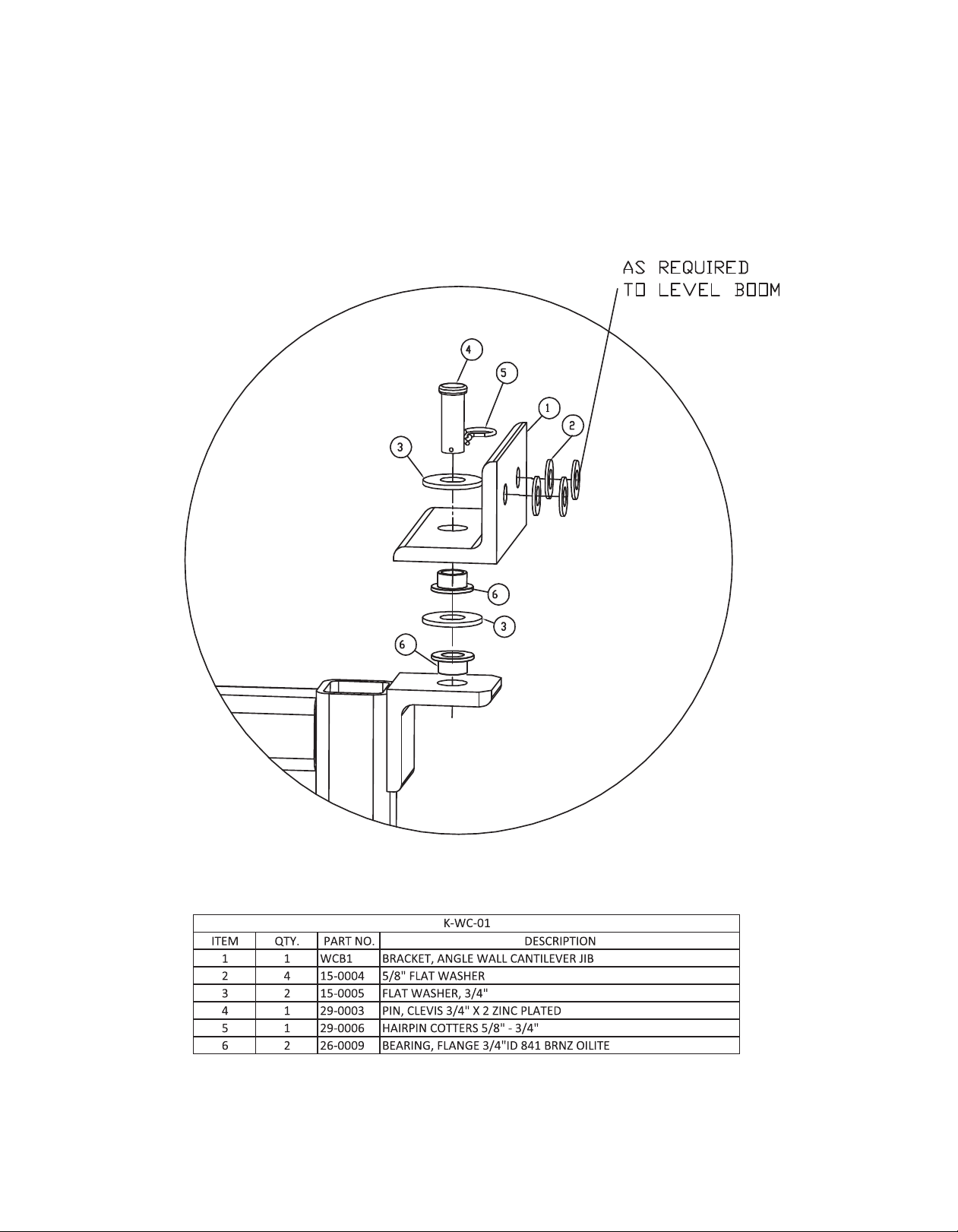
13
BO OM BRACKE ASSEMBLY:
JANUARY 2011 O JUNE 2013
WC 100, 150, 250 & 500 LBS
13
NO E: As of June 2013, we are no longer using this assembly.
he replacement assembly is K-WC-1000-R.
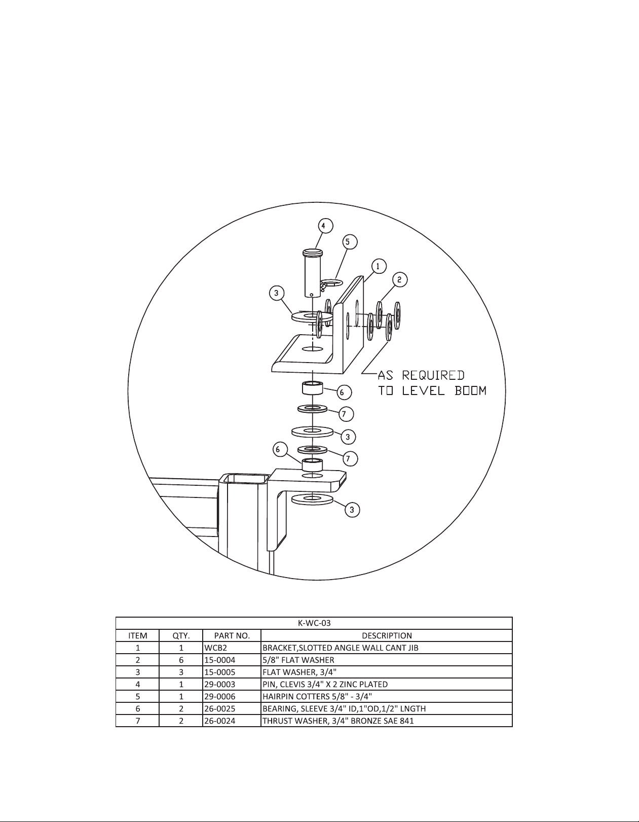
OP BRACKE ASSEMBLY:
JANUARY 2011 O JUNE 2013
WC 1000 LBS
1414
NO E: As of June 2013, we are no longer using this assembly.
he replacement assembly is K-WC-1000-R.

15
BO OM BRACKE ASSEMBLY:
JANUARY 2011 O JUNE 2013
WC 1000 LBS
ITEM QTY. PART NO. DESCRIPTION
11WCB1 BRACKET, ANGLE WALL CANTILEVER JIB
2415-0004 5/8" FLAT WASHER
3315-0005 FLAT WASHER, 3/4"
4129-0003PIN, CLEVIS 3/4" X 2 ZINC PLATED
5129-0006HAIRPIN COTTERS 5/8" - 3/4"
6226-0025BEARING,SLEEVE 3/4" ID,1"OD,1/2" LNGTH
7226-0024THRUST WASHER, 3/4" BRONZE SAE 841
K-WC-03
NO E: As of June 2013, we are no longer using this assembly.
he replacement assembly is K-WC-1000-R.

16
OP BRACKE ASSEMBLY:
JUNE 2013 AND LA ER ONLY (ALL WC’S)
WC 100, 150, 250, 500, AND 1000 LBS
NO E: his bracket assembly applies to all WC Jibs and
replacement brackets June 2013 and later.

17
BO OM BRACKE ASSEMBLY:
JUNE 2013 AND LA ER ONLY (ALL WC’S)
WC 100, 150, 250, 500, AND 1000 LBS
NO E: his bracket assembly applies to all WC Jibs and
replacement brackets June 2013 and later.

18
– Configuration for January 2011
and earlier
– All washers are installed and in the
correct locations
– Flange bearings are not beginning to pull
out and are installed in the correct
locations
– Pin is down the whole way
– Cotter pin is present
– Angles and crane are aligned horizontally
– Configuration for January 2011 to
June 2013
– All washers are installed and in the
correct locations
– Flange bearings are not beginning to pull
out and are installed in the correct
locations
– Pin is down the whole way
– Cotter pin is present
– Angles and crane are aligned horizontally
BEARING ASSEMBLY: CORREC
– Configuration for June 2013 and later
– All washers and flange bearings are
present
– Angles and crane are aligned horizontally
– Lock nut is tightened to 10 ft/lbs
– Bearings are being loaded correctly and
shoulder bolt is being stressed correctly

19
Inspection Procedure:
– Crane must be taken out of service
immediately
– Could result in serious injury or death
Problem:
– The upper flange bearing is beginning to
pull out
– Flange bearing may be wearing
incorrectly
– Pin may be exposed to wear or failure if
flange bearing pulls the entire way out
Possible Cause:
– Bracket centers are too large
Inspection Procedure:
– Crane must be taken out of service
immediately
– Could result in serious injury or death
Problem:
– Center washer is missing
Possible Cause:
– Incorrect installation
BEARING ASSEMBLY: INCORREC

20
BEARING ASSEMBLY: INCORREC
Inspection Procedure:
– Crane must be taken out of service
immediately
– Could result in serious injury or death
Problem:
– Angles or crane are misaligned
– Pin is beginning to pull out
– Upper flange bearing may be beginning
to pull out
– Flange bearing may be wearing
incorrectly
– Upper portion of pin may be exposed to
wear or failure due to misalignment
Possible Cause:
– Bracket not mounted correctly
Inspection Procedure:
– Crane must be taken out of service
immediately
– Could result in serious injury or death
Problem:
– Lower flange bearing is missing entirely
– Angle will be wearing directly on pin
without the protection of the bearing
– Pin will prematurely fail
Possible Cause:
– Lower flange bearing is missing entirely
(incorrect installation)
– Bracket centers are less than required
This manual suits for next models
4
Table of contents
Other Spanco Construction Equipment manuals


